USER GUIDE
u-line.com
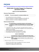
Water Hookup
Water Hookup
PREPARE PLUMBING
The water valve uses a standard 1/4” (6.35 mm)
compression tting. U-Line recommends using accessory
water hook up kit – part # 80-54674-00. The kit includes
a 10’ (3 m) braided exible water supply line and a brass
hose tting.
Plumbing installation must observe all state
and local codes. All water and drain connections
MUST BE made by a licensed/qualied plumbing
contractor. Failure to follow recommendations
and instructions may result in damage and/or
harm.
Water Supply Connection
When connecting the water supply, please note the
following:
• Before installing the unit and connecting to the cold
water supply, review the local plumbing codes.
• The water pressure should be between 20 and 120 psi
(138 and 827 kPa).
• TDS (Total Dissolved Solids) between 5 ppm (mg/L)
and 400 ppm (mg/L) and water hardness less than 200
mg/L (ppm), 12 gpg (grains per gallon).
• TDS and/or water hardness above these limits should
be treated with a reverse osmosis system or other
ltration system.
• Softened water is not recommended as it may result in
softer ice than desired.
• The water line MUST have a shut-o valve in the
supply line.
• The water line should be looped into 2 coils. This
will allow the unit to be removed for cleaning and
servicing. Make certain that the tubing is not pinched
or damaged during installation.
Do not use any plastic water supply line. The line
is under pressure at all times. Plastic may crack
or rupture with age and cause damage to your
home.
Do not use tape or joint compound when
attaching a braided exible water supply line
that includes a rubber gasket. The gasket
provides an adequate seal – other materials
could cause blockage of the valve.
Failure to follow recommendations and
instructions may result in damage and/or harm,
ooding or void the product warranty.
Use new hose set. Do not reuse old hose set.
Turn o water supply and disconnect electrical
supply to unit prior to installation.
Use caution when handling back panel. The edges
could be sharp.
CAUTION
!
CAUTION
!
CAUTION
!
10