Model No. 831.153971
Serial No.
Write the serial number in the
space above for future reference.
Serial Number Decal (under seat)
\_Visit our website at
www.weiderplatin um.com
• Assembly
• Adjustments
• Console Operation
• Part List and Drawing
_CAUTION
Read all precautions and instruc-
tions in this manual before
using this equipment. Save this
manual for future reference.
W E I D E R_
RESISTANCE SYSTEM EXERCISER
User's Manual
Sears, Roebuck and Co., Hoffman Estates, IL 60179

TABLE OF CONTENTS
WARNING DECAL PLACEMENT .......................................................... 2
IMPORTANT PRECAUTIONS ............................................................. 3
BEFORE YOU BEGIN
................................................................... 4
ASSEMBLY ........................................................................... 5
ADJUSTMENTS ...................................................................... 14
CONSOLE OPERATION ................................................................ 18
CABLE DIAGRAM ..................................................................... 20
TROUBLESHOOTING .................................................................. 21
EXERCISE GUIDELINES ............................................................... 22
ORDERING REPLACEMENT PARTS ................................................ Back Cover
FULL TEN-YEAR WARRANTY .................................................... Back Cover
Note: A PART IDENTIFICATION CHART and a PART LIST/EXPLODED DRAWING are attached in the center of
this manual. Remove the PART IDENTIFICATION CHART and PART LIST/EXPLODED DRAWING before begin-
ning assembly.
WARNING DECAL PLACEMENT
The decals shown here have been
placed on the resistance system. If a
decal is missing or illegible, please call
1-800-999-3756 to order a free replace-
ment decal. Apply the decal in the loca-
tion shown.
• Misuse of this product may result in serious
injury.
• Read user's manual and follow all warnings
and operating instructions prior to use.
• DO not allow children on or around machine.
• Replace label if damaged, illegible, or removed.
2

IMPORTANT PRECAUTIONS
before using the resistance system.
t. Read all instructions in this manual before
using the resistance system. Use the resist-
ance system only as described in this manual.
adequately informed of all precautions.
3. The resistance system is intended for home
use only. Do not use the resistance system In
any commercial, rental, or institutional setting.
11. Pull on the lower cable only while sitting on
the bench or standing on the base plate. Pull
on the high cables only while sitting on the
bench, with the seat in one of the three posi-
tions closest to the upright base, or while
standing on the base plate.
12. The resistance system is designed to be
used with the included resistance. Do not
use the resistance system with any other
type of resistance.
surface. Cover the floor beneath the resist-
ance system to protect the floor.
5, Make sure that all parts are properly tight-
ened each time the resistance system is
used. Replace any worn parts immediately.
6, Keep children under 12 and pets away from
the resistance system at all times.
7. Keep hands and feet away from moving parts.
8. Always wear athletic shoes for foot protec-
tion while exercising.
9. The resistance syat_m is designed to sup-
part a maximum user weight of 300 pounds.
10. The crossbar on the top frame is not
designed to be used for pull-up exercises. Do
not hang on the crossbar.
cables when performing an exercise that
does not require it.
14. Make sure the storage knob is in place and
fully tightened each time the resistance sys-
tem is used.
15. Make sure that the cables remain on the pul-
leys at all times. If the cables bind as you are
exercising, stop immediately and make sure
that the cables are on the pulleys.
16. Do not pull on the cables while the resist-
ance level is being adjusted.
17. If you feel pain or dizziness while exercising,
stop Immediately and begin cooling down.
Read all instructions before using. Sears assumes no responsibility for personal injury or property
damage sustained by or through the use of this product.
3

BEFORE YOU BEGIN
Thank you for selectingthe innovative WELDER®PLAT-
INUM XP8O0 resistancesystem.The resistancesystem
offersa selectionofstationsdesignedtodevelop every
majormusclegroupof the body.Whether yourgoal isto
tone yourbody,builddramaticmusclesize and
strength,or improveyourcardiovascularsystem,the
resistancesystemwillhelpyouto achievethe specific
resultsyouwant.
For your benefit, read this manual carefully before
using the resistance system. If you havequestions
after readingthismanual, call 1-800-4-MY-HOME®
(1-800-469-4663). To helpusassistyou, please note
the productmodelnumber and serialnumberbefore
calling. The modelnumberis 831.153971. The serial
numbercan be found on a decal attachedtothe resist-
ance system(see thefrontcoverofthis manual).
Before readingfurther,please reviewthe drawing below
and familiarize yourselfwiththe parts thatare labeled.
Crossbar
Lat Bar
Console
Squat Backrest
Backrest
Storage Knob
Top Frame
High Pulley
-- ResistanceBar
Squat Pin
Low Pulley
Row Plate
Seat
Seat Knob
Base Plate
Leg Level
ASSEMBLED
DIMENSIONS:
Height: 82 in.
Width: 66 in.
Depth: 80 in.
4

ASSEMBLY
This manualisdasigP_dto ensurethatthe resist-
ance systemcan be assembledsuccessfullyby
mostpeople. However,itis importantto realize
that the versatileresistancesystemhasmany
partsand that the assembly processwilltake
time. Most peoplefind_at bysettingaside plenty
oftime, assemblywillgo sm_ly.
Before beginning assembly, carefully read the
following information and instructions:
• Assembly requires two persons.
• Place all parts in a cleared area and remove the
packing materials. Do not dispose of the packing
matedals untilassembly is completed.
• For help identifying small parts, use the PART
IDENTIFICATION CHART. Note: Some small
parts may have been pre-attached for shipping. If
a part is not in the parts bag, check to see if it
has been pre-attached.
• Tightenall parts as you assemble them, unless
instructedtodo otherwise.
• As you assemble the resistance system, make
sure all parts are orientedas shown in the draw-
ings.
The included Allen w_ _ and the fol-
lowing tools (not included) are required for
assembly:
• Two adjustable wrenches
• One rubber mallet
• One standard screwdriver
• One Phillips screwdriver
• Lubricant, such as grease or petroleum jelly,
and soapy water,
Assemblywillbe more convenientifyou have a
socketset, a set of open-end or closed-end
wrenches, or a set of ratchet wrenches.
Attach the Base Plate Foot (63) to the Base Plate
(1) with two M4 x 38mm Screws (100).
2. Attach a Wheel (65) to a Wheel Insert (64) with an
M10 x 78mm Button Bolt (99) and an M1O Nylon
Locknut (103). Do not overtighten the Locknut;
the Wheel must be able to turn easily.
Attach the Wheel Insert (64) to the Base Plate (1)
with two M4 x 16mm Screws (53) and a Plastic
Foot (36).
Attach the other Wheel (65) in the same man-
ner.
100
p
_.-1 OO
103
64
1
53
99
5

3. 3
Insert the Upper Wire Harness (71) throughthe
hole in the Upright Cover (3). Pull the lower end
of the Upper Wire Harness out of the hole in the
back of the Upright (2).
Attach the Upright Cover (3) and Upright (2) to
the Base Plate (1) with an M10 x 25mm Button
Screw (88), an MIO Washer (106), an M10 x
92mm Button Bolt (83), and an M10 Nylon
Locknut (103).
4. Attach the Row Plate (28) to the Upright (2) with
four M10 x 75ram Button Bolts (84) and four MI0
Nylon Locknuts (103).
103
2_
I O3
71
.2
71
84
6

5.
Insert the four connectorsofthe lowerwire har-
ness (C) into the socketsofthe Upper Wire
Harness (71). The connectors should slide easi-
ly into the sockets and snap into place. If a con-
nector does not slide easily and snap into place,
turn the connector over and then insert it.
Make sure that the connectorsand wires appear
as shown in the inset drawing. IF THE CONNEC-
TORS ARE NOT INSERTED PROPERLY, THE
CONSOLE MAY BE DAMAGED WHEN THE
POWER IS TURNED ON.
Pull the excess lower wire hamess ('Cl out of
the Mech Frame 1'61and Push it and the UDDer
Wire Harness (71_ into the Uoriaht (2_.
Insert the Mech Frame (6) into the Base Plate (1).
Attach the Mech Frame to the Upright(2) with a
1/2"x 25mm Screw (85) and a 1/2"Lock Washer
(12). Do not tighten the Screw yet.
Attach the Mech Frame (6) to the Base Plate (1)
withfour M10 Nylon Locknuts(103).
Tighten the 1/2" x 25mm Screw (85).
6. Attach the Leg Lever Bumper (55) to the Leg (5)
with two M5 x 56mm Screws (108).
7,
Pullthe Seat Knob (48) and remove the Seat
Carriage (44) from the Rail (not shown).
Attach the Seat (45) to the Seat Carriage (44)
withfour M6 x 16mm Screws (41).
5
6
6 12
85
41
41
7

Pull the Seat Knob (48) out and slide the Seat
Carriage (44) onto the Rail (4) as shown. Engage
the Knob into a hole in the Rail.
Press the Rail Cap (49) onto the Leg (5). Attach
the Leg to the Rail (4) with two M10 x 64mm
Button Bolts (80), four M10 Washers (106), and
two M10 Nylon Locknuts (103).
9. Attach the Rail Insert (31) insideof the Rail (4)
with two M10 x 64mm Button Bolts (80), four M10
Washers (106), and two M10 Nylon Locknuts
(103). Make sure the Bolts go through the indi-
cated holes in the Rail Insert.
10. Lubricate an M10 x 125mm Button Bolt (89) with
grease. Attach the Rail (4) to the Row Plate (28)
with the Bolt, two M10 Washers (106), two 31mm
Spacers (30), and an M10 Nylon Locknut (103).
Do not overtighten the Locknut; the Rail must
be able to pivot easily.
Tighten the Storage Knob (29) into the Row Plate
(28) and the Rail (4).
11. Wet a Squat Arm (20) with soapy water. Slide a
Small Foam Pad (24) and a Short Handgrip (21)
onto the Squat Arm.
Repeat with the other Squat Arm (20).
Tighten the Squat Knob (27) into the Squat
Carriage (19) and the Squat Arm Pivot Tube (not
shown).
9
10
11
103
106 4
48
" Holes on
106 this side
49
80
31
103 106
Holes
4
106
30 106 89
Lubricate
24
21
8

12. Attach the Squat Backrest(25) to the Squat
Carriage (19) with four M6 x 16mm Screws (41).
13. Insert the Squat Pin (66) into the Upright (2).
Slide the Squat Carriage (19) onto the Upright (2).
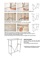
14. Attach the Top Frame (37) to the Upright (2) with
two M10 x 25mm Button Screws (88), an M10 x
75mm Button Screw (84), three M10 Lock
Washers (75), and an M10 Washer (106).
12
13
14
41
41
66
88
37
84
9

15. Pull the excess Upper Wire Harness (71) out of
the Upright (2). Insertthe connector on the
Console (67) intothe socketon the Upper Wire
Harness. The connector should slide easily into
the socket and snap into place. Iftheconnector
does not slideeasilyand snap intoplace,turnthe
connector over and then insert it.
Make sure thatthe connector and wires appear
as shown in the inset drawing. IF THE CONNEC-
TOR IS NOT INSERTED PROPERLY, THE CON-
SOLE MAY BE DAMAGED WHEN THE POWER
IS TURNED ON.
Push the excess Upper Wire Harness (71) into
the Upright (2).
Attach the Console (67) to the Upright (2) with
four M4 x 70ram Screws (114).
16. Attach a Large Pulley (14) and the Pulley Plate
(68) to the Upright (2) with an M12 x 62mm
Button Bolt (81) and an M12 Nylon Locknut (43).
Do not tighten the Locknut yet.
17. Pull the upper cable (A), which is attached inside
of the Mech Frame (not shown), up between the
Updght (2) and the Pulley Plate (68).
Attach another Large Pulley (14) to the Upright (2)
and PulleyPlate (68) with an M12 x 62mm Button
Bolt (81) and an M12 Nylon Locknut (43). Make
sure that the upper cable (A) is between the
two Pulleys.
Hold the 38mm Spacer (90) insidethe loop ofthe
upper cable (A), and between the Upright(2) and
the Pulley Plate (68). Attach the Spacer with an
M1Ox 58mm Button Screw (42). Make sure the
ends of the cable do not wrap around each
other below the Spacer and the Large Pulleys
(14) used in steps 16 and 17 (refer to the
CABLE DIAGRAM on page 20).
Tighten the M12 Nylon Locknuts (43) used in
steps 16 and 17.
18. Attach a Small Guide Spacer (18), a LargeGuide
Spacer (17), and two Bar Guides (15) to the
Upright (2) with an M10 x 152mm Bolt(86).
Pull the upper cable (A) up between the Bar
Guides (15). Press the metal cover on the cable
into the groove in the BlockSpacer (16). Attach a
Small Guide Spacer (18), the Block Spacer, the
two Bar Guides (15), an M10 Thick Washer (54),
and the two Tethers (70) to the Upright (2) with
another M10 x 152mm Bolt (86). Do not tighten
the Bolt yet.
15
16
17
18
114
f
114
68
14
2
81
_43
81
17 ._
18 86
Metal
54
7O
18 16 Groove
43
86
t0

19. Insert the Resistance Bar (9) between the Bar
Guides (15), and center it on the BlockSpacer
(not shown).
Remove the paper backing from a Bracket Plate
(11) and stick itto the end of ResistanceBar (9).
Press a Pulley Bracket (10) onto the Resistance
Bar, Screw a 318"x 38ram Tension Screw (13)
into the Pulley Bracket a couple of turns. Make
sure the hexagonal hole in the Screw is on the
outside of the Bracket.
Attach a Tether (70) to the Pulley Bracket (10) at
the upper hole, with an M10 x 64ram ButtonBolt
(80), an M10 Thick Washer (54), and an M10 Nylon
Locknut (103),
Repeat on the other side of the Resistance
Bar (9). Then, tighten the lower M10 x 152mm
Bolt (86) used in step 18.
20. Hold a Large Pulley (14) inside the upper cable
(A). Attach the Pulley to a Pulley Bracket (10)
with an M12 x 58mm Button Bolt (87) and an M12
Nylon Locknut (43). Make sure that the cable is
routed as shown in the CABLE DIAGRAM on
page 20,
21. Hold a Large Pulley (14) inside the upper cable
(A). Attach the Pulley to the other Pulley Bracket
(10) with an M12 x 58mm Button Bolt (87) and an
M12 Nylon Locknut(43). Make sure that the
cable is routed as shown in the CABLE DIA-
GRAM on page 20.
Tighten the two 3/8" x 38mm Tension Screws
(13) an equal number of turns until the upper
cable (A) is tight.
22. Attach a Plastic Foot (36) to the Backrest Frame
(32) with an M4 x 16mm Screw (53).
20
14-
-15
103
43
87
22
11

23. Attach the Backrest(35) to the Backrest Frame
(32) with four M6 x 38mm Screws (105) and four
M6 Washers (107).
24. Insert the rodon the Backrest Frame (32) into the
slot in the Seat Carriage (44). Hold the Backrest
Frame vertically over the Seat Carriage and
slide the rod into the slot, as shown in the
inset drawing.
25. Attach the Leg Lever (56) to the Leg (5) with a
Leg Station Pin (60). Slide a Cotter Pin (113) onto
the Leg Station Pin.
23
24
25
32
107
105
ot
44
56_
105
107
6O
12

26. Slide the Pad Tube (50) into the Leg Lever (56).
Slide two Large Foam Pads (52) onto the Pad
Tube.
Attach the other Pad Tube (50) to the Leg
Lever (56) and the Leg (5) in the same manner.
27. Attach a 90mm Pulley (40) insideof the Leg (5)
with an M10 x 85mm Button Bolt (92), two M10
Washers (106), two 22mm Spacers (61), and an
M10 Nylon Locknut (103).
28. Wrap a High Cable (101) over a 90mm Pulley
(40). Attach the Pulley to a Pulley Housing (39)
with an M10 x 44mm Button Bolt (93) and an M10
Nylon Locknut (103).
Repeat this step with the other High Cable
(101) and Pulley Housing (39).
27
28
103--*,,
106_,
52
61
q_" .106
103-_. 93
4_0 "_101
29. Make sure that all parts have been properly tight-
ened. The use of the remaining parts will be
explained in ADJUSTMENTS, beginning on the
following page.
Before using the resistance system, turn on
the console and change the resistance setting
as described in CONSOLE OPERATION on
page 18. Refer to TROUBLESHOOTING on
page 21 and adjust the Crossbar Cable ten-
sion as described.
13

ADJUSTMENTS
This sectionexplains how to adjust the resistance system. See the EXERCISE GUIDELINES on page 22 for
importantinformation abouthow to get the most benefitfrom your exercise program.Also, refer to the accompa-
nying exercise guide to see the correctformfor each exercise.
Make sure all parts are propedy tightened each time the resistancesystem isused. Replace wornparts immedi-
ately.The resistancesystem can be cleanedwith a damp clothand a mild, non-abrasivedetergent.Do not use
solvents.The resistancebar can be cleanedwith a vinyland rubberprotectant,availableat an automotiveor
departmentstore.
ATTACHING THE HIGH PULLEYS
To use a high pulley, slidethe hook on the Pulley
Housing (39) ontoan hookon the Top Frame (37).
Attach the end of the High Cable (101) without the
ball to the end of the lower cable (B) with e Cable
Clip (94). Attach the other high pulley in the same
manner,
Remove the high pulleys when not in use.
USING THE LEG LEVER
To use the Leg Lever (56), attach it to the Leg (5) with
a Leg Station Pin (60). Slide a Cotter Pin (113) onto
the Leg Station Pin.
Route the hook end of the Leg Lever Cable (102)
under the 90mm Pulley (40) in the Leg (5), and attach
it to the Leg Lever (56). Make sure the hook is ori-
ented as shown when attaching it to the Leg
Lever. Insert a Leg StationPin (60) intothe Leg,
underthe Cable, Slide a Cotter Pin (113) ontothe Lag
StationPin.
See the inset drawing. Attacha long end ofthe Leg
Lever Cable (102) to one end of the lower cable (B)
with a Cable Clip (94). Attach the other long end of
the Leg Lever Cable to the other end of the low
cable in the same manner.
102
101 --
56
94
60
60
14

ADJUSTING THE SQUAT ARM
To adjustthe Squat Arm (20), remove the Squat Knob
(27) from Squat Carriage (19). Move the Arm to the
up or down position,and reengage the Knob intothe
Squat Carriage.
ATTACHING THE SQUAT STATION
To use the squat station,first remove the backrest
(see ADJUSTING THE BACKREST below). Next,
adjust the squat arm to the up position (see ADJUST-
ING THE SQUAT ARM above). Then, inserta Squat
Pin (66) into the correct hole in the Upright (2).
Finally, attach each end of the lower cable (B) to the
Squat Carriage (19) with a Carriage Strap (77) and
two Cable Clips (94).
Note: The Squat Pin (66) will determine the lowest
point to which the Squat Carriage (19) can
descend. The Squat Carriage should not be able to
descend so low that the user could become
trapped under the Squat Arm (20).
ADJUSTING THE BACKREST
The Backrest (35) can be used in a level positionor an
inclined position. To use the Backrest in a level posi-
tion, secure the Seat Carriage (44) at the adjustment
hole in the Rail (4) closest to the Leg (not shown) (see
ADJUSTING THE SEAT on page 16).
To use the Backrest (35) in an inclined position,
secure the Seat Carriage (44) at one of the other
adjustment holes in the Rail (4). Rest the Backrest
against the Upright (2).
For row exercises, removethe Backrest (35) from the
Seat Carriage (44). Holdthe Backrestverticallyover
the Seat Carriage and liftthe rod out ofthe slot (see
the insetdrawing).
2O
44
35
66
15

ATTACHING THE ACCESSORIES
To attach the Lat Bar (82) to the highpulleys, first
attach the high pulleyto the resistance system(see
ATTACHING THE HtGH PULLEYS on page 14). Then,
attach the Lat Bar to a High Cable (101) with a Cable
Clip (94). Attach the Lat Bar to the other High Cable
in the same manner.
The Handles (not shown) and theAnkle Strap (not
shown) can be attached to the High Cables (101) or
the lower cable (not shown) with Cable Clips (94).
Attach the Hip Strap (not shown) to the ends of the
lowercable w_thtwo Cable Clips.
ADJUSTING THE SEAT
The Seat (45) can be secured at various positions on
the Rail (4). To move the Seat, pull the Seat Knob
(48) out as far as it will go and slide the Seat to the
desired position. Engage the Seat Knob into an
adjustment hole in the Rail.
To perform row exercises, the hipstrap must be
attached to the mech cable (see ATTACHING THE
ACCESSORIES above), and the Seat Carriage (44)
must be able to roll along the Rail (4). First, remove
the Backrest (35) from the Seat Carriage (see
ADJUSTING THE BACKREST on page 15). Then,
pull the Seat Knob (48) out as far as it will go, and
turn the Knob so that the pin rests at the end of the
"L"-shaped slot (see the inset drawing).
101
4
Adjustment
Hole
35-
45
16

STORING THE RESISTANCE SYSTEM
To store the resistance system, first remove the Curl
Pad (not shown)and the Leg Lever(not shown) from
the resistance system. Secure the Seat Carriage (44)
at the position closest to the Leg (5) (see ADJUSTING
THE SEAT on page 16). Next, remove the Storage
Knob (29) from the Row Plate (28). Lift the Leg toward
the Top Frame (37), and tighten the Storage Knob into
the side of the Row Plate and into the Rail (4).
To move the resistance system, stand behind the
Upright (2) and place the toe of your shoe on the end
of the Base Plate (1) and hold the resistance system
in the indicated area. Tilt the resistance system back
onto the Wheels (65) and roll it to the new location.
37
Hold in
this area
17

CONSOLE OPERATION
FEATURES OF THE CONSOLE
Console--
Program
Buttons--
Main
Display--
Resistance
Display
Sets
Display--
Reps
Display
Nr_F
_EC_
:HES
_EP CU
_OJLOER
_RM_ISE
UPPER BODY ABS & BACK LOWER BODY
PROGRAMS PROGRAMS PROGRAMS
CHEST PRESS 1
CERTIFIED PERSONAL TR_JNER SXERCISE
_IGHT _JUSTMENT
The heart of the resistance system is the digital resist-
ance training console. The console offers both a man-
ual mode and nine workout programs. When the man-
ual mode is selected, the resistance setting can be
changed with the touch of a button. When a program is
selected, the consolewill guide you through an effec-
tive upper body, ab and back, or lower body workout.
To use the manual mode of the console, follow the
steps at the right. To use a program, see page 19.
PLUGGING IN THE RESISTANCE SYSTEM
Plugthe indicated
end ofthe
Transformer(72) into
the Back Mech
Cover (8). Plugthe
otherend of the
Transformerintoa
12g-voltoutlet.All
indicatorsand dis-
plays on the console
72
will flash once; the console will then be ready for use.
The motor may be heard while the resistance system
calibrates itseff. Important: Always plug in the tranS-
former when using the resistance system.
MANUAL OPERATION
I. Plug In the transformer.
Plug the transformer into a 120wolt outlet (see
PLUGGING IN THE RESISTANCE SYSTEM
above). Important: Always plug in the trans-
former when using the resistance system.
Note: When the power is on,the wordsSELECT
PROGRAM willappearin the main display. Touse a
program, see PROGRAM OPERATION on page 19.
If no buttons are pressedand no cables are pulled
for ten minutes, the console will go to sleep. Press
any button to resume exercising.
2. Select a resistance setting,
The currentresistance setting will appear in the
resistance display. To selecta different resistance
setting, first make sure that no cables are being
pulled. Next, pressthe resistance+ and - buttons.
Each time a buttonis pressed, the resistanceset-
tingwillincrease or decrease by 1 pound.To
change the resistancesettingquickly,holddown
one of the buttons.
Note: While the resistance settingis changing, the
motor will be heard. To prevent damage to the
motor, do not pull any of the cables while the
resistance setting is changing. Ifa cable is
pulled,the words RELEASE HANDLES AND
READJUST RESISTANCE AS DESIRED may
appear inthe main display.
18

Note: The resistance system uses progressive
resistance. As the resistance bar begins to bend,
the amount of resistance will increase gradually. As
the bar bends further, the resistance will increase
rapidly.
3. Enter the numbers of sets and repetitions that
you plan to complete for an exercise.
Toenter the number of sets that you plan to do,
press the SETS + and - buttons. To enter the num-
ber of repetitions that you plan to do, press the
REPS + and - buttons.
Note: If you do not enter the numbers of sets and
repetitions that you plan to do, the console will count
the total number of repetitions that you complete
during your workout.
4. Perform the exercise.
If you have entered numbersof sets and repetitions,
the console will count down the repetitions and sets
you have completed. When you complete the exer-
cise, repeat steps 2 and 3 above for the next exer-
cises.
5. Unplug the transformer.
When you completeyourworkout,unplugthetrans-
formerfromthe 120-voltoutlet.
3. Row for five minutes to warm up.
PROGRAM OPERATION
1. Plug in the transformer,
Plug the transformer into a 120-volt outlet (see
PLUGGING IN THE RESISTANCE SYSTEM on
page 18). Important: Always plug in the trans-
former when using the resistance system.
Note: If no buttons are pressed and no cables are
pulled for ten minutes, the console will go to sleep.
Press any button to resume exercising.
2. Select a program.
When the power is on, the words SELECT PRO-
GRAM will appear in the main display. Toselect e
program, press one of the nine program buttons.
The indicator on the button you press will light.
Note: The console offersthree upper body pro-
grams, three ab and back programs, and three
lower body programs. If you wish to exercise your
upper body and if your goal is to lose weight, for
example, press the LOSE WEIGHT button below the
words UPPER BODY PROGRAMS.
4.
When a program is selected, the wordsCARDIO
ROW willappear in themain display. To warm up,
perform the cardio row exercise while the main dis-
play counts down from 5 minutes.
Note: To see the correct form for the cardio row
exercise, see the included exercise guide. If the
resistance setting is too high or too low, select a dif-
ferent resistance setting by pressing the resistance
+ and - buttons.
Adjust the resistance setting and the numbers of
sets and repetitions for the exercise if desired.
The name ofan exercisein the program willappear
in the maindisplay. The recommendedresistance
settingand the recommended numbersof setsand
repetitionsforthe exercisewillappear inthethree
displays belowthe maindisplay.
The recommended resistance setting and the rec-
ommendednumbersof sets and repetitions may be
too high or too low for you, depending on such fac-
tors as your body size and your physical condition. If
desired, adjust the resistance setting and the num-
bers of sets and repetitions by pressing the + and -
buttons below each display.
5. Perform the exercise.
As you perform theexercise, the console willcount
down the numbers of sets and repetitionsyou have
completed.
When you complete the exercise, the word REST-
ING will appear in the main display. It is recom-
mended that you rest while the main display counts
down.
6. Perform the remaining exercises in the program.
7.
After you have completed an exercise in the pro-
gram, press the NEXT button and the name of the
next exercise will appear in the main display. Repeat
steps 4 and 5 above for the exercise.
Note:The program may includethe same exercise
twice, with different resistance settingsand different
numbersof sets and repetitions.Ifyou wishto skip
any part ofthe program,pressthe NEXT buttonto
advance to the nextpartofthe program.
When you complete the program, the words WORK-
OUT COMPLETE will appear in the main display.
Unplug the transformer.
When you complete your workout, unplug the trans-
former from the 120-volt outlet.
19

CABLE DIAGRAM
The cable diagram shows the properrouting of the
upper cable (A). Use the diagram to make sure that
the cable has been assembled correctly.Ifthe cable
has not been correctlyrouted,the resistancesystem
will notfunction propedyand damage may occur.The
numbers showthe correctroutefor the cable. Make
sure that the ends of the cable do not wrap
around each other between positions 1 and 2, and
5 and 6.
Upper Cable (A)
3
20
Page is loading ...
Page is loading ...
Page is loading ...
Page is loading ...
Page is loading ...
Page is loading ...
Page is loading ...
Page is loading ...
/