Page is loading ...

A-1
Catalyst 6500 Series Switches Installation Guide
OL-5781-07
APPENDIX
A
Power Supply Specifications
This appendix describes the Catalyst 6500 series power supplies and provides their specifications. This
appendix contains the following sections:
• Power Supply Compatibility Matrix, page A-2
• 950 W AC-Input and DC-Input Power Supplies, page A-5
• 1000 W AC-Input Power Supply, page A-10
• 1300 W AC-Input and DC-Input Power Supplies, page A-13
• 1400 W AC-Input Power Supply, page A-18
• 2500 W AC-Input and DC-Input Power Supplies, page A-23
• 2700 W AC-Input and DC-Input Power Supplies, page A-29
• 3000 W AC-Input Power Supply, page A-36
• 4000 W AC-Input and DC-Input Power Supplies, page A-41
• 6000 W AC-Input and DC-Input Power Supplies, page A-46
• 8700 W AC-Input Power Supply, page A-54
• AC Power Cord Illustrations, page A-63
• Power Supply Redundancy, page A-73
Table A-1 lists the currently available Catalyst 6500 series switch power supplies and the power supply
description location.
Table A-1 Catalyst 6500 Series Power Supplies
Power Supply
Rating
AC-Input Model
Product Number
DC-Input Model
Product Number
950 W
1
PWR-950-AC PWR-950-DC
1000 W WS-CAC-1000W Not Available
1300 W WS-CAC-1300W WS-CDC-1300W
1400 W
1
PWR-1400-AC Not Available
2500 W WS-CAC-2500W WS-CDC-2500W
2700 W
2
PWR-2700-AC/4 PWR-2700-DC/4
3000 W WS-CAC-3000W Not Available

A-2
Catalyst 6500 Series Switches Installation Guide
OL-5781-07
Appendix A Power Supply Specifications
Power Supply Compatibility Matrix
Note The Catalyst 6500 series switches allow you to mix AC-input and DC-input power supplies in the same
chassis.
Note Many telco organizations require a –48 VDC power supply to accommodate their power distribution
systems. From an operational perspective, the DC-input power supply has the same characteristics as the
AC-input version.
Power Supply Compatibility Matrix
Table A-2 lists the compatibility of the power supplies with the Catalyst 6500 switch chassis.
4000 W WS-CAC-4000W-US1
WS-CAC-4000W-INT
PWR-4000-DC
6000 W WS-CAC-6000W PWR-6000-DC
8700 W WS-CAC-8700W-E Not Available
1. For use with the Catalyst 6503 and Catalyst 6503-E switches only.
2. For use with the Catalyst 6504-E switch only.
Table A-1 Catalyst 6500 Series Power Supplies (continued)
Power Supply
Rating
AC-Input Model
Product Number
DC-Input Model
Product Number
Table A-2 Catalyst 6500 Series Switch Supported Power Supply Configurations
Platform Supported Power Supplies Chassis/Power Supply Restrictions
Catalyst 6503
• 950 W AC-input and DC-input
• 1400 W AC-input
• The 950 W AC-input power
supply requires a PEM-15A-AC
Power Entry Module (PEM).
• The 1400 W AC-input power
supply requires a
PEM-20A-AC+ Power Entry
Module (PEM).
Catalyst 6503-E
• 950 W AC-input and DC-input
• 1400 W AC-input
• The 950 W AC-input power
supply requires a PEM-15A-AC
Power Entry Module (PEM).
• The 1400 W AC-input power
supply requires a
PEM-20A-AC+ Power Entry
Module (PEM).
Catalyst 6504-E
• 2700 W AC-input and DC-input No restrictions

A-3
Catalyst 6500 Series Switches Installation Guide
OL-5781-07
Appendix A Power Supply Specifications
Power Supply Compatibility Matrix
Catalyst 6506 • 1000 W AC-input
• 1300 W AC-input and DC-input
• 2500 W AC-input and DC-input
• 3000 W AC-input
• 4000 W AC-input and DC-input
• 6000 W AC-input and DC-input
• 8700 W AC-input
The 6000 W AC-input, 6000 W
DC-input, and the 8700 W AC-input
power supplies are limited to
4000 W when they are installed in
the Catalyst 6506 switch chassis.
Catalyst 6506-E
• 2500 W AC-input and DC-input
• 3000 W AC-input
• 4000 W AC-input and DC-input
• 6000 W AC-input and DC-input
• 8700 W AC-input
No restrictions.
Catalyst 6509
• 1000 W AC-input
• 1300 W AC-input, and DC-input
• 2500 W AC-input and DC-input
• 3000 W AC-input
• 4000 W AC-input and DC-input
• 6000 W AC-input and DC-input
• 8700 W AC-input
The 6000 W AC-input, 6000 W
DC-input, and the 8700 W AC-input
power supplies are limited to
4000 W when they are installed in
the Catalyst 6509 switch chassis.
Catalyst 6509-E
• 2500 W AC-input and DC-input
• 3000 W AC-input
• 4000 W AC-input and DC-input
• 6000 W AC-input and DC-input
• 8700 W AC-input
No restrictions.
Catalyst 6509-NEB
• 1000 W AC-input
• 1300 W AC-input and DC-input
• 2500 W AC-input and DC-input
• 3000 W AC-input
• 4000 W AC-input and DC-input
• 6000 W AC-input and DC-input
• 8700 W AC-input
The 6000 W AC-input, 6000 W
DC-input, and the 8700 W AC-input
power supplies are limited to
4000 W when they are installed in
the Catalyst 6509-NEB switch
chassis.
Table A-2 Catalyst 6500 Series Switch Supported Power Supply Configurations (continued)
Platform Supported Power Supplies Chassis/Power Supply Restrictions

A-4
Catalyst 6500 Series Switches Installation Guide
OL-5781-07
Appendix A Power Supply Specifications
Power Supply Compatibility Matrix
Catalyst 6509-NEB-A • 2500 W AC-input and DC-input
• 3000 W AC-input
• 4000 W AC-input and DC-input
• 6000 W AC-input and DC-input
• 8700 W AC-input
The 6000 W AC-input, 6000 W
DC-input, and the 8700 W AC-input
power supplies are limited to
4500 W maximum output when they
are installed in the
Catalyst 6509-NEB-A switch
chassis.
Catalyst 6509-V-E
• 2500 W AC-input and DC-input
• 3000 W AC-input
• 4000 W AC-input and DC-input
• 6000 W AC-input and DC-input
• 8700 W AC-input
No restrictions.
Catalyst 6513
• 2500 W AC-input and DC-input
• 3000 W AC-input
• 4000 W AC-input and DC-input
• 6000 W AC-input and DC-input
• 8700 W AC-input
The 8700 W AC-input power supply
is limited to 6000 W maximum
output when it is installed in the
Catalyst 6513 switch chassis.
Table A-2 Catalyst 6500 Series Switch Supported Power Supply Configurations (continued)
Platform Supported Power Supplies Chassis/Power Supply Restrictions

A-5
Catalyst 6500 Series Switches Installation Guide
OL-5781-07
Appendix A Power Supply Specifications
950 W AC-Input and DC-Input Power Supplies
950 W AC-Input and DC-Input Power Supplies
The 950 W AC-input (PWR-950-AC) and DC-input (PWR-950-DC) power supplies can be installed in
the Catalyst 6503 and Catalyst 6503-E switch chassis only. Due to form factor differences, the 950 W
AC-input and DC-input power supplies cannot be installed in any other Catalyst 6500 series switch
chassis.
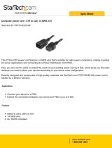
The 950 W power supplies (see Figure A-1) do not connect directly to source AC or source DC but use
Power Entry Modules (PEMs), located on the front of the Catalyst 6503 and Catalyst 6503-E switch
chassis, to connect the site power source to the power supply located in the back of the chassis. The form
factor is the same for the AC-input and DC-input power supplies.
The AC-input PEM (shown in Figure A-2) and DC-input PEM (shown in Figure A-3) provide an input
power connection on the front of the switch chassis to connect the site power source to the power supply.
You can connect the DC-input power supply to the power source with heavy gauge wiring connected to
a terminal block. The actual wire gauge size is determined by local electrical codes and restrictions.
Note The system (NEBS) ground serves as the primary safety ground for Catalyst 6503 and Catalyst 6503-E
chassis that are equipped with 950 W DC-input power supplies and DC-input PEMs. The DC-input
power supplies for these chassis do not have a separate ground.
The PEMs have an illuminated power switch (AC-input model only), current protection, surge and EMI
suppression, and filtering functions.
Figure A-1 950 W AC- and DC-Input Power Supplies
Figure A-2 950 W AC-Input PEM (PEM-15A-AC)

A-6
Catalyst 6500 Series Switches Installation Guide
OL-5781-07
Appendix A Power Supply Specifications
950 W AC-Input and DC-Input Power Supplies
Figure A-3 DC Power Entry Module (PEM)
950 W Power Supply Specifications
Table A-3 lists the specifications for the 950 W AC-input power supply.
Table A-3 950 W AC-Input Power Supply Specifications
Specification Description
AC-input type Autoranging input with power factor correction (PFC)
Note Power factor correction is a standard feature on all Catalyst 6500
series AC-input power supplies. PFC reduces the reactive
component in the source AC current allowing higher power
factors (typically 99 percent or better) and lower harmonic
current components.
AC-input voltage
• Low-line (120 VAC nominal)—85 VAC (min) to 132 VAC (max)
• High-line (230 VAC nominal)—170 VAC (min) to 264 VAC (max)
AC-input current
• 12 A @ 120 VAC
• 6A @ 230VAC
AC-input frequency 50/60 Hz (nominal)

A-7
Catalyst 6500 Series Switches Installation Guide
OL-5781-07
Appendix A Power Supply Specifications
950 W AC-Input and DC-Input Power Supplies
Branch circuit requirement Each chassis power supply should have its own dedicated, fused-branch
circuit:
• For North America—15 A
• For International—Circuits sized to local and national codes
• All Catalyst 6500 series AC-input power supplies require
single-phase source AC.
• All AC power supply inputs are fully isolated.
–
Source AC can be out of phase between multiple power supplies
in the same chassis, which means that PS1 can be operating
from phase A and PS2 can be operating from phase B.
–
For high-line operation, the power supply operates with the hot
conductor wired to a source AC phase and the neutral conductor
wired either to ground or to another source AC phase as long as
the net input voltage is in the range of 170 to 264 VAC.
–
Source AC can be out of phase between AC inputs on power
supplies that are equipped with multiple AC inputs, which
means that power cord 1 can be plugged into phase A and
power cord 2 can be plugged into phase B.
Power supply output
capacity
950 W maximum (100–240 VAC)
Power supply output
• 15 A @ +1.5 VDC
• 2.5 A @ +3.3 VDC
• 19.15 A @ +50 VDC
Output holdup time 20 ms minimum
kVA rating
1
1.32 kVA
Heat dissipation 4441 BTU/hour (approx.)
Weight 8.2 lb (3.7 kg)
1. The kVA rating listed for the power supply should be used as the sizing criteria for both UPS outputs as well as standard
circuits and transformers to power a switch.
Table A-3 950 W AC-Input Power Supply Specifications (continued)
Specification Description

A-8
Catalyst 6500 Series Switches Installation Guide
OL-5781-07
Appendix A Power Supply Specifications
950 W AC-Input and DC-Input Power Supplies
Table A-4 lists the specifications for the 950 W DC-input power supply.
Table A-5 lists the power supply LEDs and their meanings.
Table A-4 950 W DC-Input Power Supply Specifications
Specification Description
DC-input voltage –48 VDC to –60 VDC continuous
DC-input current
• 38 A @ –48 VDC
• 30 A @ –60 VDC
Power supply output
capacity
950 W
Power supply output
• 15 A @ +1.5 VDC
• 2.5 A @ +3.3 VDC
• 19.15 A @ +50 VDC
Output holdup time 4 ms
Heat dissipation 4632 BTU/hour (approx.)
Weight 8.4 lb (3.8 kg)
Table A-5 950 W AC-Input and DC-Input Power Supply LEDs
LED Meaning
INPUT OK AC-input power supplies:
• Green—Source AC voltage is OK. (Input voltage is 85 VAC or
greater.)
• Off—Source AC voltage falls below 70 VAC, is not present, or the
PEM is turned off.
DC-input power supplies:
• Green—Source DC voltage is OK. (–40.5 VDC or greater.)
• Off—Source DC voltage falls below –33 VDC or is not present at
the PEM.
FAN OK Green—Power supply fan is operating properly.
Off—Power supply fan failure is detected.
OUTPUT FAIL Red—Problem with one or more of the DC-output voltages of the power
supply is detected.
Off—DC-output voltages within acceptable margins.
Note For proper operation of the OUTPUT FAIL LED, systems with
single power supplies must be configured with a minimum of
one fan tray and one supervisor engine. Systems with dual power
supplies must have a minimum configuration of one fan tray, one
supervisor engine, and one additional module. Failure to meet
these minimum configuration requirements can cause a false
power supply output fail signal.

A-9
Catalyst 6500 Series Switches Installation Guide
OL-5781-07
Appendix A Power Supply Specifications
950 W AC-Input and DC-Input Power Supplies
950 W Power Supply AC Power Cords
Table A-6 lists the 950 W AC-input power supply AC power cords specifications. These power cords
plug into the 950 W PEM(PEM-15A-AC), not directly into the power supply. The table includes
references to power cord illustrations.
Note All 950 W power supply power cords are 8 feet 2 inches (2.5 meters) in length.
Note All 950 W power supply power cords have an IEC60320/C15 appliance connector at one end. The
appliance connector has a 90° left bend.
Table A-6 950 W AC-Input Power Supply Power Cords
Locale Power Cord
Part Number
AC Source Plug Type Cordset Rating Power Cord
Reference
Illustration
Argentina CAB-7KACR= IRAM 2073 10 A, 250 VAC Figure A-25
Australia, New Zealand CAB-AC10A-90L-AU= SAA AS 3112 10 A, 250 VAC Figure A-20
Continental Europe CAB-AC10A-90L-EU= CEE 7/7 10 A, 250 VAC Figure A-21
Italy CAB-AC10A-90L-IT= CEI 23-16/7 10 A, 250 VAC Figure A-22
Japan, North America CAB-AC15A-90L-US= NEMA 5-15 15 A, 125 VAC Figure A-23
United Kingdom CAB-AC10A-90L-UK= BS 1363
1
1. Plug contains a 13 A fuse.
10 A, 250 VAC Figure A-24

A-10
Catalyst 6500 Series Switches Installation Guide
OL-5781-07
Appendix A Power Supply Specifications
1000 W AC-Input Power Supply
1000 W AC-Input Power Supply
The 1000 W AC-input power supply (WS-CAC-1000W) is supported in the following Catalyst 6500
series switches:
• Catalyst 6506
• Catalyst 6509
• Catalyst 6509-NEB
The 1000 W power supply (shown in Figure A-4) shares the same form factor as the 1300 W, 2500 W,
3000 W, 4000 W, and 6000 W AC-input power supplies.
Figure A-4 1000 W AC-Input Power Supply

A-11
Catalyst 6500 Series Switches Installation Guide
OL-5781-07
Appendix A Power Supply Specifications
1000 W AC-Input Power Supply
1000 W Power Supply Specifications
Table A-7 lists the specifications for the 1000 W AC-input power supply.
Table A-7 1000 W Power Supply Specifications
Specification Description
AC-input type Autoranging input with power factor correction (PFC)
Note Power factor correction is a standard feature on all Catalyst 6500
series AC-input power supplies. PFC reduces the reactive
component in the source AC current allowing higher power
factors (typically 99 percent or better) and lower harmonic
current components.
AC-input voltage
• Low-line (120 VAC nominal)—85 VAC (min) to 132 VAC (max)
• High-line (230 VAC nominal)—170 VAC (min) to 264 VAC (max)
AC-input current
• 12 A @ 120 VAC
• 6 A @ 230 VAC
AC-input frequency 50/60 Hz (nominal)
Branch circuit requirement Each chassis power supply should have its own dedicated, fused-branch
circuit:
• For North America—15 A or 20 A
• For International—Circuits sized to local and national codes
• All Catalyst 6500 series AC-input power supplies require
single-phase source AC.
• All AC power supply inputs are fully isolated.
–
Source AC can be out of phase between multiple power supplies
in the same chassis, which means that PS1 can be operating
from phase A and PS2 can be operating from phase B.
–
For high-line operation, the power supply operates with the hot
conductor wired to a source AC phase and the neutral conductor
wired either to ground or to another source AC phase as long as
the net input voltage is in the range of 170 to 264 VAC.
–
Source AC can be out of phase between AC inputs on power
supplies that are equipped with multiple AC inputs, which
means that power cord 1 can be plugged into phase A and
power cord 2 can be plugged into phase B.

A-12
Catalyst 6500 Series Switches Installation Guide
OL-5781-07
Appendix A Power Supply Specifications
1000 W AC-Input Power Supply
Table A-8 list the power supply LEDs and their meanings.
Power supply output
capacity
1000 W
Power supply output
• 15 A @ +3.3 VDC
• 5A @ +5VDC
• 6A @ +12VDC
• 20.3A @ +42VDC
Output holdup time 20 ms minimum
kVA rating
1
1.25 kVA
Heat dissipation 4213 BTU/hour (approx.)
Front panel LEDs
Weight 14.8 lb (6.7 kg)
1. The kVA rating listed for the power supply should be used as the sizing criteria for both UPS outputs as well as standard
circuits and transformers to power a switch.
Table A-7 1000 W Power Supply Specifications (continued)
Specification Description
Table A-8 1000 W Power Supply LEDs
LED Meaning
INPUT OK
• Green—Source AC voltage is OK. (Input voltage is 85 VAC or
greater.)
• Off—Source AC voltage falls below 70 VAC, is not present, or the
power supply is turned off.
FAN OK
• Green—Power supply fan is operating properly.
• Off—Power supply fan failure is detected.
OUTPUT FAIL
• Red—Problem with one or more of the DC-output voltages of the
power supply is detected.
• Off—DC-output voltage with acceptable margins.
Note For proper operation of the OUTPUT FAIL LED, systems with
single power supplies must be configured with a minimum of
one fan tray and one supervisor engine. Systems with dual power
supplies must have a minimum configuration of one fan tray, one
supervisor engine, and one additional module. Failure to meet
these minimum configuration requirements can cause a false
power supply output fail signal.

A-13
Catalyst 6500 Series Switches Installation Guide
OL-5781-07
Appendix A Power Supply Specifications
1300 W AC-Input and DC-Input Power Supplies
1000 W Power Supply AC Power Cords
Table A-9 lists the specifications for the AC power cords that are available for the 1000 W AC-input
power supply. The table includes references to power cord illustrations.
Note All 1000 W power supply power cords are 8 feet 2 inches (2.5 meters) in length.
Note All 1000 W power supply power cords have an IEC60320/C15 appliance plug at one end.
1300 W AC-Input and DC-Input Power Supplies
The 1300 W AC-input power supply (WS-CAC-1300W) and 1300 W DC-input power supply
(WS-CDC-1300W) are supported in the following Catalyst 6500 series switches:
• Catalyst 6506
• Catalyst 6509
• Catalyst 6509-NEB
The 1300 W power supply (see Figure A-5 for the 1300 W AC-input power supply and Figure A-6 for
the 1300 W DC-input power supply) shares the same form factor as the 1000 W, 2500 W, 3000 W,
4000 W, and 6000 W AC-input power supplies.
Table A-9 1000 W AC-Input Power Supply Power Cords
Locale Power Cord
Part Number
AC Source Plug Type Cordset Rating Power Cord
Reference
Illustration
Argentina CAB-7KACR= IRAM 2073 10 A, 250 VAC Figure A-25
Australia, New Zealand CAB-7KACA= SAA AS 3112 15 A, 250 VAC Figure A-26
Continental Europe CAB-7KACE= CEE 7/7 16 A, 250 VAC Figure A-27
Italy CAB-7KACI= CEI 23-16/7 10 A, 250 VAC Figure A-28
Japan, North America CAB-7KAC-15= NEMA 5-15 15 A, 125 VAC Figure A-29
United Kingdom CAB-7KACU= BS 1363
1
1. Plug contains a 13 A fuse.
10 A, 250 VAC Figure A-30

A-14
Catalyst 6500 Series Switches Installation Guide
OL-5781-07
Appendix A Power Supply Specifications
1300 W AC-Input and DC-Input Power Supplies
Figure A-5 1300 W AC-input Power Supply
Figure A-6 1300 W DC-Input Power Supply

A-15
Catalyst 6500 Series Switches Installation Guide
OL-5781-07
Appendix A Power Supply Specifications
1300 W AC-Input and DC-Input Power Supplies
1300 W Power Supply Specifications
Table A-11 lists the specifications for the 1300 W AC-input power supply.
Table A-10 1300 W AC-Input Power Supply Specifications
Specification Description
AC-input type Autoranging input with power factor correction (PFC).
Note Power factor correction is a standard feature on all Catalyst 6500
series AC-input power supplies. PFC reduces the reactive
component in the source AC current allowing higher power
factors (typically 99 percent or better) and lower harmonic
current components.
AC-input voltage
• Low-line (120 VAC nominal)—85 VAC (min) to 132 VAC (max)
• High-line (230 VAC nominal)—170 VAC (min) to 264 VAC (max)
AC-input current
• 16 A @ 120 VAC
• 8 A @ 230 VAC
AC-input frequency 50/60 Hz (nominal) (±3 Hz for full range)
Branch circuit requirement Each chassis power supply should have its own dedicated, fused-branch
circuit:
• For North America—15 A or 20 A
• For International—Circuits sized to local and national codes
• All Catalyst 6500 series AC-input power supplies require
single-phase source AC.
• All AC power supply inputs are fully isolated.
–
Source AC can be out of phase between multiple power supplies
in the same chassis, which means that PS1 can be operating
from phase A and PS2 can be operating from phase B.
–
For high-line operation, the power supply operates with the hot
conductor wired to a source AC phase and the neutral conductor
wired either to ground or to another source AC phase as long as
the net input voltage is in the range of 170 to 264 VAC.
–
Source AC can be out of phase between AC inputs on power
supplies that are equipped with multiple AC inputs, which
means that power cord 1 can be plugged into phase A and
power cord 2 can be plugged into phase B.
Power supply output
capacity
• 1300 W maximum (AC-input)
• 1360 W maximum (DC-input)
Power supply output
• 15 A @ +3.3 VDC
• 5A @ +5VDC
• 6A @ +12VDC
• 27.46 A @ +42 VDC
Output holdup time 20 ms minimum

A-16
Catalyst 6500 Series Switches Installation Guide
OL-5781-07
Appendix A Power Supply Specifications
1300 W AC-Input and DC-Input Power Supplies
Table A-11 lists the specifications for the 1300 W DC-input power supply.
Table A-12 lists the 1300 W power supply LEDS and their meanings.
kVA rating
1
1.625 kVA
Heat dissipation 5478 BTU/hour (approx.)
Weight 18.4 lb (8.3 kg)
1. The kVA rating listed for the power supply should be used as the sizing criteria for both UPS outputs as well as standard
circuits and transformers to power a switch.
Table A-10 1300 W AC-Input Power Supply Specifications (continued)
Specification Description
Table A-11 1300 W DC-Input Power Supply Specifications
Specification Description
DC-input voltage –48 VDC to –60 VDC continuous
DC-input current
• 39 A @ –48 VDC
• 31 A @ –60 VDC
Power supply output
capacity
1360 W maximum (DC-input)
Power supply output
• 15 A @ +3.3 VDC
• 5A @ +5VDC
• 6A @ +12VDC
• 28.9A @ +42VDC
DC input terminal block Accepts 3–10 AWG copper conductors. Actual size of the wire needed
is determined by the installer or local electrician. Terminal block
material is rated at 120°C.
Output holdup time 8 ms
Heat dissipation 6447 BTU/hour (approx.)
Weight 21.0 lb (9.5 kg)

A-17
Catalyst 6500 Series Switches Installation Guide
OL-5781-07
Appendix A Power Supply Specifications
1300 W AC-Input and DC-Input Power Supplies
1300 W Power Supply AC Power Cords
Table A-13 lists the specifications for the AC power cords that are available for the 1300 W AC-input
power supply. The table includes references to power cord illustrations.
Note All 1300 W power supply power cords are 14 feet (4.3 meters) in length.
Note All 1300 W power supply power cords have an IEC60320/C19 appliance connector at one end.
Table A-12 1300 W AC-Input and DC-Input Power Supply LEDs
LED Meaning
INPUT OK AC-input power supplies:
• Green—Source AC voltage is OK. (Input voltage is 85 VAC or
greater.)
• Off—Source AC voltage falls below 70 VAC, is not present, or the
power supply turned off.
DC-input power supplies:
• Green—Source DC voltage is OK. (Input voltage is –40.5 VDC or
greater.)
• Off—Source DC voltage falls below –33 VDC, is not present, or the
power supply is turned off.
FAN OK
• Green—Power supply fan is operating properly.
• Off—Power supply fan failure is detected.
OUTPUT FAIL
• Red—Problem with one or more of the DC-output voltages of the
power supply is detected.
• Off—DC-output voltages within acceptable margins.
Note For proper operation of the OUTPUT FAIL LED, systems with
single power supplies must be configured with a minimum of
one fan tray and one supervisor engine. Systems with dual power
supplies must have a minimum configuration of one fan tray, one
supervisor engine, and one additional module. Failure to meet
these minimum configuration requirements can cause a false
power supply output fail signal.

A-18
Catalyst 6500 Series Switches Installation Guide
OL-5781-07
Appendix A Power Supply Specifications
1400 W AC-Input Power Supply
1400 W AC-Input Power Supply
The 1400 W AC-input power supply (PWR-1400-AC) can be installed in the Catalyst 6503 switch and
Catalyst 6503-E switch chassis only. Due to form factor differences, the 1400 W AC-input power supply
cannot be installed in any other Catalyst 6500 series switch chassis.
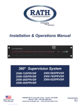
The 1400 W power supplies (see Figure A-7) do not connect directly to source AC but use power entry
modules (PEMs), located on the front of the Catalyst 6503 and Catalyst 6503-E switch chassis, to
connect the site power source to the power supply located in the back of the chassis.
The AC-input PEM (PEM-20A-AC+) (shown in Figure A-8) provides an input power connection on the
front of the router chassis to connect the site power source to the power supply.
The PEMs have an illuminated power switch, current protection, surge and EMI suppression, and filtering
functions.
Figure A-7 1400 W AC-Input Power Supply (PWR-1400-AC)
TableA-13 1300W Power Supply AC Power Cords
Locale Power Cord
Part Number
AC Source Plug Type Cordset Rating Power Cord
Reference
Illustration
Argentina CAB-7513ACR= IRAM 2073 10 A, 250 VAC Figure A-31
Australia, New Zealand CAB-7513ACA= SAA AS 3112 15 A, 250 VAC Figure A-32
Continental Europe CAB-7513ACE= CEE 7/7 16 A, 250 VAC Figure A-33
Israel CAB-AC-2500W-ISRL= SI16S3 16 A, 250 VAC Figure A-34
Italy CAB-7513ACI= CEI 23-16/7 16 A, 250 VAC Figure A-35
Japan, North America CAB-7513AC= NEMA 5-20
1
1. For Japan, ask your local electrical contractor to prepare the NEMA 5-20 power plug.
20 A, 125 VAC Figure A-36
People’s Republic of
China
CAB-AC16A-CH= GB16C 16 A, 250 VAC Figure A-37
South Africa CAB-7513ACSA= IEC 884-1 16 A, 250 VAC Figure A-38
Switzerland CAB-ACS-10= SEV 1011 10 A, 250 VAC Figure A-39
United Kingdom CAB-7513ACU= BS 1363
2
2. Plug contains a 13 A fuse.
13 A, 250 VAC Figure A-40

A-19
Catalyst 6500 Series Switches Installation Guide
OL-5781-07
Appendix A Power Supply Specifications
1400 W AC-Input Power Supply
Figure A-8 1400 W AC-Input PEM (PEM-20A-AC+)
1400 W Power Supply Specifications
Table A-14 lists the specifications for the 1400 W AC-input power supply.
Table A-14 1400 W AC-Input Power Supply Specifications
Specification Description
AC-input type Autoranging input with power factor correction (PFC).
Note Power factor correction is a standard feature on all Catalyst 6500
series AC-input power supplies. PFC reduces the reactive
component in the source AC current allowing higher power
factors (typically 99 percent or better) and lower harmonic
current components.
AC-input voltage
• Low-line (120 VAC nominal)—85 VAC (min) to 132 VAC (max)
• High-line (230 VAC nominal)—170 VAC (min) to 264 VAC (max)
AC-input current
• 16 A @ 120 VAC
• 8 A @ 230 VAC
AC-input frequency 50/60 Hz (nominal) (±3 Hz for full range)

A-20
Catalyst 6500 Series Switches Installation Guide
OL-5781-07
Appendix A Power Supply Specifications
1400 W AC-Input Power Supply
Table A-15 lists the 1400 W AC-input power supply LEDs and their meanings.
Branch circuit requirement Each chassis power supply should have its own dedicated, fused-branch
circuit:
• For North America—20 A
• For International—Circuits sized to local and national codes
• All AC power supply inputs are fully isolated.
–
Source AC can be out of phase between multiple power supplies
in the same chassis, which means that PS1 can be operating
from phase A and PS2 can be operating from phase B.
–
For high-line operation, the power supply operates with the hot
conductor wired to a source AC phase and the neutral conductor
wired either to ground or to another source AC phase as long as
the net input voltage is in the range of 170 to 264 VAC.
–
Source AC can be out of phase between AC inputs on power
supplies that are equipped with multiple AC inputs, which
means that power cord 1 can be plugged into phase A and
power cord 2 can be plugged into phase B.
Power supply output
capacity
1400 W
Power supply output
• 15 A @ +1.5 V
• 2.5 A @ +3.3 V
• 27.4A @ +50V
Output holdup time 20 ms minimum
kVA rating
1
1.75 kVA
Heat dissipation 5976 BTU/hour (approx.)
Weight 7.8 lb (3.5 kg)
1. The kVA rating listed for the power supply should be used as the sizing criteria for both UPS outputs as well as standard
circuits and transformers to power a switch.
Table A-14 1400 W AC-Input Power Supply Specifications (continued)
Specification Description
/