Page is loading ...

INSTALLATION AND OPERATION MANUAL
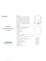
CNGE4+2SMS[POE][HO]
10/100/1000 MBPS INTELLIGENT REDUNDANT RING
GIGABIT SWITCH WITH OPTIONAL POE+
The ComNet CNGE4+2SMS[POE][HO] is a four port intelligent switch with light
management functionality. It provides two 10/100/1000Base-T(X) copper ports and
two 100/1000Base-FX SFP ports. The CNGE4+2SMS[POE][HO] provides exclusive
functionality for easy field deployment including DIP switch based operation of
RSTP for creating redundant network topologies as well as preventing network video
flooding of multicast traffic with IGMP snooping. Copper ports 1 through 4 can
optionally supply up to thirty (30) watts of power per port based on the IEEE 802.3at
standard. An optional High Output (HO) version is also available that can supply up to
sixty (60) watts of PoE from copper ports 1 through 4. This product is fully compatible
with the ComNet exclusive CopperLine® SFP modules for operation over extended
distance UTP or Coax cable. The ComNet exclusive Port Guardian feature provides
additional cyber security protection by enabling physical port lockout in the event that
an existing cable is disconnected and prevents a potential network incursion using
common spoofing techniques. The intrusion event is reported back to the operator
using SNMP.
This manual serves the following
ComNet Model Numbers:
CNGE4+2SMS
CNGE4+2SMSPOE
CNGE4+2SMSPOEHO

INS_CNGE4+2SMS_REV– 02/19/13 PAGE 2
INSTALLATION AND OPERATION MANUAL CNGE4+2SMS[POE][HO]
TECH SUPPORT: 1.888.678.9427
Contents
Regulatory Compliance Statement 4
Warranty 4
Disclaimer 4
Safety Indications 4
Overview 5
Introduction 5
Software Features 5
Hardware Features 6
Hardware Overview 7
Side Panels 7
Indicating LEDs 10
Cables 11
Ethernet Cables 11
10/100/1000BASE-T(X) Pin Assignments 11
SFP 13
Console Cable 13
DIP Switches 14
WEB Management 22
Configuration by Web Browser 22
System Information 25
Switch Port Configuration 26
Port Statistics 27
RSTP System Configuration 28
RSTP Port Configuration 29
Active Ping Check Configuration 30
Non PoE Model CNGE4+2SMS 30
PoE Model CNGE4+2SMSPOE and CNGE4+2SMSPOEHO 31
Authentication Username and Password Configuration 32
Upgrade Firmware 33
Factory Defaults 34

INS_CNGE4+2SMS_REV– 02/19/13 PAGE 3
INSTALLATION AND OPERATION MANUAL CNGE4+2SMS[POE][HO]
TECH SUPPORT: 1.888.678.9427
System Reset 35
Network Interface Configuration 36
SNMP 37
CNGE4+2SMSPOE[HO] PoE-PSE-Status Information 38
CNGE4+2SMSPOE[HO] PoE Contact Information 39
Port Guardian 40
Port Guardian – CLI Reset 41
Static Multicast MAC Routing Per Port 42
Static MAC Lock Configuration 43
IGMPv2 Snooping 44
Jumbo Frame support 46
Command Line Interface Management 47
Configuration by Command Line Interface (CLI). 47
Firmware Upgrade Procedure 50
Technical Specifications 52

INS_CNGE4+2SMS_REV– 02/19/13 PAGE 4
INSTALLATION AND OPERATION MANUAL CNGE4+2SMS[POE][HO]
TECH SUPPORT: 1.888.678.9427
Regulatory Compliance Statement
Product(s) associated with this publication complies/comply with all applicable regulations. Please
refer to the Technical Specifications section for more details.
Warranty
ComNet warrants that all ComNet products are free from defects in material and workmanship
for a specified warranty period from the invoice date for the life of the installation. ComNet will
repair or replace products found by ComNet to be defective within this warranty period, with
shipment expenses apportioned by ComNet and the distributor. This warranty does not cover
product modifications or repairs done by persons other than ComNet-approved personnel, and
this warranty does not apply to ComNet products that are misused, abused, improperly installed,
or damaged by accidents.
Please refer to the Technical Specifications section for the actual warranty period(s) of the
product(s) associated with this publication.
Disclaimer
Information in this publication is intended to be accurate. ComNet shall not be responsible for its
use or infringements on third-parties as a result of its use. There may occasionally be unintentional
errors on this publication. ComNet reserves the right to revise the contents of this publication
without notice.
Safety Indications
» The equipment can only be accessed by trained ComNet service personnel.
» This equipment should be installed in secured location.

INS_CNGE4+2SMS_REV– 02/19/13 PAGE 5
INSTALLATION AND OPERATION MANUAL CNGE4+2SMS[POE][HO]
TECH SUPPORT: 1.888.678.9427
Overview
Introduction
The CNGE4+2SMS is a light managed, hardened Ethernet switch that contains many features.
The switch will work under a wide variety of temperature, dirty and humid conditions. It can be
managed through WEB, USB Console or other third-party SNMP software. With the easy to use
and intuitive web and CLI interfaces, the switch can be easily monitored by a utility called eVision,
which is part of the ComNet eConsole software suite.
eConsole is network management software that is very effective. With easy to use and intuitive
interface, you can easily monitor the status of the switches.
Software Features
» Supports SNMPv1/v2c
» Event notification by SNMP trap and Relay Output (Relay Output for PoE models only)
» Web-based GUI and USB Console CLI configuration
» Enable/disable ports
» PoE status monitoring and health check
» RSTP (802.1w)
» IGMP snooping v2 (64 groups)
» Jumbo Frame support (10240 MTU)
» Static MAC lock (per port)
» Static multicast MAC routing
» Field firmware upgrade capable
» Port Guardian physical port lockout feature
» Active ping check with SNMP trap, port reset & port shutdown capability

INS_CNGE4+2SMS_REV– 02/19/13 PAGE 6
INSTALLATION AND OPERATION MANUAL CNGE4+2SMS[POE][HO]
TECH SUPPORT: 1.888.678.9427
Hardware Features
» 7 × DIP Switches for quick feature selection
» 2 × Redundant DC power inputs
» Operating Temperature: -40 – 75ºC
» Storage Temperature: -40 – 85ºC
» Operating Humidity: 5% – 95%, non-condensing
» 2 × 10/100/1000Base-T(X) Gigabit Ethernet port
» 2 × 100/1000Base-X SFP
» 2 × Dry Contact Inputs
» 2 × Form A Relays
» USB Console Port
» Dimensions: 4.1 × 3.7 × 1.46 in (10.4 × 9.4 × 3.7 cm)

INS_CNGE4+2SMS_REV– 02/19/13 PAGE 7
INSTALLATION AND OPERATION MANUAL CNGE4+2SMS[POE][HO]
TECH SUPPORT: 1.888.678.9427
Hardware Overview
Side Panels
The following table describes the ports that are on the sides of the CNGE4+2SMS.
Port Description
10/100/1000Base-T(X)
RJ-45 Ethernet ports
4 × 10/100/1000Base-T(X) RJ-45 fast Ethernet ports support
auto-negotiation.
Default Settings:
Speed: auto
Duplex: auto
Flow control: disable
SFP Ports 2 × 100/1000Base-X SFP
USB Console Use the included mini USB cable to manage the switch.

INS_CNGE4+2SMS_REV– 02/19/13 PAGE 8
INSTALLATION AND OPERATION MANUAL CNGE4+2SMS[POE][HO]
TECH SUPPORT: 1.888.678.9427
3 42
8
7
11
6
1
5
10
9
CNGE4+2SMS
1. Power Connections
2. LED for PWR1
3. LED for PWR2
4. LED for STATUS
5. Console Mini USB
6. Configuration DIP switches
7. Contact Closure terminal block
8. RJ-45 Ports 1-4
9. Data Speed DIP switches
10. Link/Activity LEDs for SFP Ports 5 and 6
11. SFP Ports 5 and 6

INS_CNGE4+2SMS_REV– 02/19/13 PAGE 9
INSTALLATION AND OPERATION MANUAL CNGE4+2SMS[POE][HO]
TECH SUPPORT: 1.888.678.9427
2 31
8
6
7
12
5
4
11
10
9
CNGE4+2SMSPOE
2 31
8
6
7
12
5
4
11
10
9
CNGE4+2SMSPOEHO
1. LED for Power 1
2. LED for Power 2
3. LED for Status
4. Console Mini USB
5. Configuration DIP switches
6. Contact Closure terminal block
7. Power connections
8. RJ-45 Ports 1-4
9. PoE Status LEDs for RJ-45 Ports
10. Data Speed DIP switches
11. Link/Activity LEDs for SFP Ports 5 and 6
12. SFP Ports 5 and 6

INS_CNGE4+2SMS_REV– 02/19/13 PAGE 10
INSTALLATION AND OPERATION MANUAL CNGE4+2SMS[POE][HO]
TECH SUPPORT: 1.888.678.9427
Indicating LEDs
LED Color Status Description
PWR1 Green On DC Power Input 1 Good
Off No power detected
PWR2 Green On DC Power Input 2 Good
Off No power detected
STATUS Green On Initialization passed
Red On Failed
10/100/1000Base-T(X) Ethernet ports
LNK /ACT Green On Port link up
Blinking Data transmitting
1000 Mbps indicator Amber On Port speed is 1000 Mbps
30W/60W Amber On 30W PoE power being supplied (POE & POEHO units only)
Green On 60W PoE power being supplied (POEHO units only)
SFP
LNK /ACT Green On Port link up.
Blinking Data transmitted.

INS_CNGE4+2SMS_REV– 02/19/13 PAGE 11
INSTALLATION AND OPERATION MANUAL CNGE4+2SMS[POE][HO]
TECH SUPPORT: 1.888.678.9427
Cables
Ethernet Cables
The CNGE4+2SMS switches have standard Ethernet ports. According to the link type, the switches
use CAT 3, 4, 5, & 5e UTP cables to connect to any other network device (PCs, servers, switches,
routers, or hubs). Please refer to the following table for cable specifications.
Cable Types and Specifications
Cable Type Max. Length Connector
10BASE-T Cat. 3, 4, 5 100Ω UTP 100m (328ft) RJ-45
100BASE-TX Cat. 5 100Ω UTP UTP 100m (328ft) RJ-45
1000BASE-TX Cat. 5/Cat. 5e 100Ω UTP UTP 100m (328ft) RJ-45
10/100/1000BASE-T(X) Pin Assignments
With 100BASE-T(X)/10BASE-T cable, pins 1 and 2 are used for transmitting data, and pins 3 and 6
are used for receiving data.
10/100 Base-T RJ-45 Pin Assignments
Pin Number Assignment
1 TD+
2 TD-
3 RD+
4 Not used
5 Not used
6 RD-
7 Not used
8 Not used
Note: “+” and “-” signs represent the polarity of the wires that make up each wire pair.

INS_CNGE4+2SMS_REV– 02/19/13 PAGE 12
INSTALLATION AND OPERATION MANUAL CNGE4+2SMS[POE][HO]
TECH SUPPORT: 1.888.678.9427
1000 Base-T RJ-45 Pin Assignments
Pin Number Assignment
1 BI_DA+
2 BI_DA-
3 BI_DB+
4 BI_DC+
5 BI_DC-
6 BI_DB-
7 BI_DD+
8 BI_DD-
The CNGE4+2SMS switches support auto MDI/MDI-X operation. You can use a straight-through
cable to connect PC to switch. The following table below shows the 10/100BASE-T(X) MDI and
MDI-X port pin-outs:
10/100 Base-T MDI/MDI-X pin assignments
Pin Number MDI port MDI-X port
1 TD+ (transmit) RD+ (receive)
2 TD- (transmit) RD- (receive)
3 RD+ (receive) TD+ (transmit)
4 Not used Not used
5 Not used Not used
6 RD- (receive) TD- (transmit)
7 Not used Not used
8 Not used Not used
1000 Base-T MDI/MDI-X pin assignments
Pin Number MDI port MDI-X port
1 BI_DA+ BI_DB+
2 BI_DA- BI_DB-
3 BI_DB+ BI_DA+
4 BI_DC+ BI_DD+
5 BI_DC- BI_DD-
6 BI_DB- BI_DA-
7 BI_DD+ BI_DC+
8 BI_DD- BI_DC-

INS_CNGE4+2SMS_REV– 02/19/13 PAGE 13
INSTALLATION AND OPERATION MANUAL CNGE4+2SMS[POE][HO]
TECH SUPPORT: 1.888.678.9427
SFP
The Switch has fiber optic ports that utilize SFP connectors. ComNet offers a wide selection of SFP
modules that offer different fiber type, connector type and distances. Please remember that the
TX port of Switch A should be connected to the RX port of Switch B.
Switch A Fiber Cord Switch B
Console Cable
Each CNGE4+2SMS switch can have the initial network settings configured by the management
console port. You can connect them to a PC with USB Ports using the supplied USB to USB Mini B
male plug cable.
USB to USB Mini B Cable

INS_CNGE4+2SMS_REV– 02/19/13 PAGE 14
INSTALLATION AND OPERATION MANUAL CNGE4+2SMS[POE][HO]
TECH SUPPORT: 1.888.678.9427
DIP Switches
The CNGE4+2SMS’s dip switches configure switch features. The DIP Switches are numbered from
left to right when viewing the side of the Switch with the backplate on the bottom and the power
connections on the left. If “Web Management Enable” is selected in the management software
under System Settings, the DIP switch settings will be overridden by any settings made in the
browser interface.
Location
on Unit
DIP Switch
Position Description
Rear
1 RSTP enable (down = disabled, up enabled)
2 Root Bridge Select
3 Port SMS Mux
4 IGMP enable
5 Redundant SFP mode
Front
1 SFP Port 3 speed. Up: 1000M/Down: 100M
2 SFP Port 4 speed. Up: 1000M/Down: 100M
Switch Function Listing
The switch functions may be set individually or may be combined in the following order to perform
enhanced functions above the individual operation. The table below describes the operation of the
switch functions. This same table is also available in the help menu of the system webpage.
Summary of the switch configurations (in order of switch priority)
RSTP
(Switch 1)
R BRIDGE
(Switch 2)
MUX
(Switch 3)
R SFP
(Switch 5)
Resulting Mode Comment
ON OFF OFF OFF RSTP All ring configurations
ON ON OFF OFF RSTP RSTP this bridge set to root
OFF OFF ON OFF SMS
Port 6 is uplink (traffic from
ports 1-5 is sent only to port 6)
OFF OFF ON ON
SMS with
Redundant SFP
Fiber fail over with ports 1
through 5 isolation
OFF OFF OFF ON Redundant SFP
Fiber fail over
Port 5 is primary port

INS_CNGE4+2SMS_REV– 02/19/13 PAGE 15
INSTALLATION AND OPERATION MANUAL CNGE4+2SMS[POE][HO]
TECH SUPPORT: 1.888.678.9427
SMS MUX Disabled (DIP Switch 3 in OFF Position)
Ports 1-4
Multicast Traffic
Port 5
Multicast Traffic
Port 6
To Next Device
Multicast traffic will be
flooded on all ports like
a standard unmanaged
switch.
SMS MUX Enabled (DIP Switch 3 in ON Position)
Ports 1-4
Multicast Traffic
Ports 1-4
Multicast Traffic
Port 5
Multicast Traffic
Port 5
Multicast Traffic
Port 6
To Next Device
Port 6
To Next Device
IGMP Enabled on Managed Head End Switch
Multicast traffic is
diverted only to port 6,
preventing flooding on
the local device
Multicast traffic is
diverted only to port 6,
preventing flooding on
the local device

INS_CNGE4+2SMS_REV– 02/19/13 PAGE 16
INSTALLATION AND OPERATION MANUAL CNGE4+2SMS[POE][HO]
TECH SUPPORT: 1.888.678.9427
Redundant SFP (RSFP) Enabled (DIP Switch 5 in ON Position)
Ports 1-4
Ports 1-4
Port 6
(Secondary)
Port 6
(Secondary)
Port 5
(Primary)
Port 5
(Primary)
All traffic from Ports 1-4
is sent over Port 5 which
is the Primary Port
All traffic from Ports 1-4
is sent over Port 5 which
is the Primary Port
Normal Operation Condition
Note: There is no port isolation between Ports 1 - 4 as shown. Ports 1 - 4 are free to send traffic
between each other as per a normal switch.
Redundant SFP (RSFP) Enabled (DIP Switch 5 in ON Position)
Ports 1-4 Ports 1-4
Port 6
(Secondary)
Port 6
(Secondary)
Port 5
(Primary)
Port 5
(Primary)
All traffic from Ports 1-4
is switched to transmit
over Port 6 in less than
one second.
All traffic from Ports 1-4
is switched to transmit
over Port 6 in less than
one second.
Port 4 Fault Condition
Note: There is no port isolation between Ports 1 - 4 as shown. Ports 1 - 4 are free to send traffic
between each other as per a normal switch.
When Port 5 comes back online all traffic from Ports 1 - 4 is switched back to transmit over
Port 5 in less than 1 second.

INS_CNGE4+2SMS_REV– 02/19/13 PAGE 17
INSTALLATION AND OPERATION MANUAL CNGE4+2SMS[POE][HO]
TECH SUPPORT: 1.888.678.9427
Redundant SFP (RSFP) Enabled (3rd Party Switch) (DIP Switch 5 in ON Position)
Ports 1-4
Port 6
(Secondary)
Port 5
(Primary)
3rd Party Switch
Secondary Primary
All traffic from Ports 1-4
is sent over Port 5 which
is the Primary Port
Normal Operation Condition
Note: Disabling MAC Address Learning on the 3rd party switch (if supported) can sometimes
allow for faster port switchover times.
There is no port isolation between Ports 1 - 4 as shown. Ports 1 - 4 are free to send traffic
between each other as per a normal switch.
Redundant SFP (RSFP) Enabled (3rd Party Switch) (DIP Switch 5 in ON Position)
Ports 1-4
Port 6
(Secondary)
Port 5
(Primary)
3rd Party Switch
Secondary Primary
All traffic from Ports 1-4
is sent over Port 5 which
is the Primary Port
Port 5 Fault Condition
Note: Disabling MAC Address Learning on the 3rd party switch (if supported) can sometimes
allow for faster port switchover times.
There is no port isolation between Ports 1 - 5 as shown. Ports 1 - 4 are free to send traffic
between each other as per a normal switch.
When Port 5 comes back online all traffic from Ports 1 - 4 is switched back to transmit over
Port 5 in less than 1 second.

INS_CNGE4+2SMS_REV– 02/19/13 PAGE 18
INSTALLATION AND OPERATION MANUAL CNGE4+2SMS[POE][HO]
TECH SUPPORT: 1.888.678.9427
Redundant SFP (RSFP) Enabled + SMS MUX Enabled (3rd Party Switch) (DIP Switch 3 & 5 ON)
Port 1-4 Traffic
IGMP Enabled on Managed Switch
Secondary Primary
Port 6
t(Secondary)
Port 5
(Primary)
All traffic from Ports 1-4
is sent over Port 5 which
is the Primary Port
Multicast traffic is
diverted only to port 5
Normal Operation Condition
Note: Disabling MAC Address Learning on the 3rd party switch (if supported) can sometimes
allow for faster port switchover times.
Multicast traffic is diverted only to port 6 preventing flooding on the local device between
Ports 1 - 4. Ports 1 - 4 are isolated from each other.
Redundant SFP (RSFP) Enabled + SMS MUX Enabled (3rd Party Switch) (DIP Switch 3 & 5 ON)
IGMP Enabled on Managed Switch
Port 1-4 Traffic
Secondary Primary
Port
6(Secondary)
Port 5
(Primary)
All traffic from Ports 1-4
is switched to transmit
over Port 6 in less than 1
second.
Multicast traffic is
diverted only to port 6
X
Port 4 Fault Condition
Note: Disabling MAC Address Learning on the 3rd party switch (if supported) can sometimes
allow for faster port switchover times.
Multicast traffic is diverted only to port 5 preventing flooding on the local device between
Ports 1 - 4. Ports 1 - 4 are isolated from each other.
When Port 6 comes back online all traffic from Ports 1 - 4 is switched back to transmit over
Port 6 in less than 1 second.

INS_CNGE4+2SMS_REV– 02/19/13 PAGE 19
INSTALLATION AND OPERATION MANUAL CNGE4+2SMS[POE][HO]
TECH SUPPORT: 1.888.678.9427
RSTP Enabled (Single Ring) (DIP Switch 1 ON)
Attention: ComNet recommends maximum number of units per ring is limited to 20 devices.
Numbers higher than this may cause undesired performance and are not supported
by ComNet.
Note: The unit at the control room location should have DIP switch 3 ON (ROOT BR). This will
force the ring to break at the half way point and ensure most effective load sharing on the
network.
See Note
Below
CNGE4+2SMS
CNGE4+2SMS
CNGE4+2SMS
CNGE4+2SMS
CNGE4+2SMS
CNGE4+2SMS
CNGE4+2SMSCNGE4+2SMS

INS_CNGE4+2SMS_REV– 02/19/13 PAGE 20
INSTALLATION AND OPERATION MANUAL CNGE4+2SMS[POE][HO]
TECH SUPPORT: 1.888.678.9427
RSTP Enabled (Multiple Rings) (DIP Switch 1 ON)
Attention: ComNet recommends maximum number of units per ring is limited to 20 devices.
Numbers higher than this may cause undesired performance and are not supported
by ComNet.
Attention: Central switch must be manually configured to be the root bridge. This requirement is
mandatory for correct performance in a multiple ring scenario.
Attention: ComNet recommends maximum number of rings per core switch is limited to 3-4.
The actual number supported will depend on the processing power of the core switch
used and other features that may be enabled on the core switch. Please contact
ComNet Technical Support to discuss your application prior to ordering.
CNGE4+2SMS
CNGE4+2SMS
CNGE4+2SMS
CNGE4+2SMS
CNGE4+2SMS
CNGE4+2SMS
CNGE4+2SMS
CNGE4+2SMS
CNGE4+2SMS
CNGE4+2SMS
CNGE4+2SMS
CNGE4+2SMS
CNGE4+2SMSCNGE4+2SMS
/