Page is loading ...

Ericsson Inc.
Private Radio Systems
Mountain View Road
Lynchburg, Virginia 24502
1-800-528-7711 (Outside USA, 804-528-7711) Printed in U.S.A.
MOUNTING PLATE KIT FOR WEATHERPROOF CASE
19A149703G1
19D438723P2 Base
N24P21012 Cap screw: NO. 1/4-20 X 34
4035664P15 Lock nut: No. 1/4-20.
N400P71 Flat washer. (Quantity 6).
19A149756G1 Ground strap.
N24P21016 Cap screw: No. 1/4-20 X 1.
N402P41B6 Washer. (Quantity 1).
7115130P9 Lock washer, internal tooth: No. 3/8.
19D904965P1 Antenna Support
N210P21B6 Nut, machine screw, Hex, steel, 1/4-20.
MICROPHONE HANGER
(With Strong Spring)
19A149690G1
N30AP16010 Machine screw, indented hex head: No. 10-32 X5/8
4031457G1 Support.
4031458G2 Spring.
4035664P14 Nut, self-locking: No. 10-32.
WEATHERPROOF FUSE KIT
19A149701G1
19A149677P1 Fuseholder: 30 Amps, 600 Volts; sim to Bussman Tron
Type weatherproof assembly.
19A149451P1 Fuseholder: 30 Amps, 32 volts. Sim to Bussman Type HFB.
19A149678P2 Fuse: 20 Amps, 125 Volts; sim to Bussman BAF-20.
MISCELLANEOUS
19D903677P1 Top Mounting Plate
LBI-39023
Installation Manual
S-825 CONTROL UNIT
& RANGR
®
RADIO UNIT
MOTORCYCLE INSTALLATION

2
TABLE OF CONTENTS
Page
GENERAL INFORMATION..........................................................3
TOOLS REQUIRED...................................................................3
USER SUPPLIED EQUIPMENT:...............................................5
EQUIPMENT SUPPLIED:..........................................................5
INSTALLATION...........................................................................5
EQUIPMENT.................................................................................6
CONTROL UNIT MOUNTING.....................................................7
TWO-WAY RADIO MOUNTING.................................................9
POWER CONSIDERATIONS ....................................................9
MOUNTING THE RADIO..........................................................9
CABLE INSTALLATION..............................................................15
POWER/CONTROL CABLE......................................................16
VEHICLE SYSTEM CABLE......................................................18
MICROPHONE BRACKET........................................................20
SPEAKER MOUNTING.............................................................21
CONTROL UNIT CONNECTIONS............................................21
ANTENNA INSTALLATION........................................................22
TOP COVER POSITION............................................................22
REAR MOUNT OPTION............................................................22
FINAL CHECKS AND CONNECTIONS.......................................24
HEADSET OPTION INSTALLATION..........................................26
Copyright © November 1994, Ericsson Inc.
35
PARTS LIST
INSTALLATION HARDWARE KIT
S-825 CONTROL UNIT
Select, Conventional 19D901146G3
Deluxe, Conventional 19D901146G4
EDACS Trunked 19D901146G5
EDACS Trunked 19D901146G6
Antenna Ground Strap
19A149758G1
19A115799P2
Solderless Terminal
19A115799P4
Solderless terminal
WEATHERPROOF CASE ASSEMBLY
19D438453G3
19B235039P1
Cam
19B235038P1
Catch
19A149531G1
Support
19A134583P6
Seal, Rubber
19B209539P4
Rim Lock: sim to Chicago Lock Co. Cat # 4260-1
19A149454P1
Hinge: sim to Bronson Cat. # B-SS-3474-SS-R
N194P1506B6
Screw, thread forming: No. 8-18 X 3/8. (Used to secure
ground plane)
N400AP6
Washer, flat steel narrow plate, No. 4.
5490407P36
Rubber grommet, Inner diameter 1/2 inch.
19B235151P1
Cover, plate.
N97P13008
Machine screw, pan head: No. 6-32 X 1/2.
4035664P13
Nut, self-locking: No. 6-32.
19A116552P4
Cable clip.
N30AP16010
Machine screw, indented hex head: No. 10-32 X 5/8.
N406P39
Washer, lock, No. 10.
N400P9
Washer, flat.
N402P8B6
Flat washer, steel: No. 8.
19D438722P1
Ground plane.
19J706152P3
Strap: sim to Panduit Corp. SST-1.
344A3989G1
Shock mount assembly.
19B802204P2
Dampener, cellular urethane, 8 1/4 X 8
3/8 X 0.062 inch; sim to Poron 4701-01-20-062-1604.
(Used with bottom mounting plate.)
19A116838P1
Adhesive coating
19D903778P1
Bottom mounting plate.
349A9531P1
Strap.
SAA70303/02
Protective cap.

34
Figure 24. Antenna Cutting Chart, 450-512 MHz
3
GENERAL INFORMATION
The procedures in this manual cover the motorcycle installation of an
S-825 Series Control Unit, a RANGR two-way radio, and associated items.
The instructions in this manual are typical installation instructions, and are
not intended to cover all makes and models of motorcycles available.
To simplify installation and minimize difficulties, it is suggested that the
installer read the entire manual pertaining to this application before
starting the installation.
NOTICE
Ericsson Inc. does not assume liability for possible
degradation of the radio performance or motorcycle
performance due to installers mounting procedure. Radio
installation shall be in the horizontal plane.
TOOLS REQUIRED
A few specific tools are required to complete the motorcycle installation.
These are:
• Soldering iron,
• Wire crimpers (ST2602),
• (9/64") drill for backup plate mounting screws,
• TORX driver,
• Adjustable wrench or 5/16" and 7/16" box wrench,
• Hex drivers: #10, #25, and #30,
• 1/2-20 bolts,
• Flat blade screwdriver, and
• Hex wrench set for motorcycle fairing.
TORX is a registered Trademark of CAMCAR Division of Textron, Inc.

4
Figure 1. Typical S-825 Series Motorcycle Installation
33
Figure 23. Antenna Cutting Chart, 136-174 MHz

32
Figure 22. Antenna Cutting Chart, 29-50 MHz
5
USER SUPPLIED EQUIPMENT:
• Motorcycle Mounting Bracket
• RTV
EQUIPMENT SUPPLIED:
• Weatherproof Box -19D438453G3
• Weatherproof case base mounting bracket - 19D438723P2
• Top Mounting Plate, 19D903777P1
• Bottom Mounting Plate, 19D903778P1
• RANGR Top Cover, 188D5003P1
• Rubber pad, 19B802204P1
• Installation Parts packet
• Rear Mount Antenna Support Bracket (Optional) - 19D904965
INSTALLATION
The standard Installation consists of the following:
• Mounting the S-825 control unit,
• Mounting the weatherproof base plate to the motorcycle bracket,
• Installing the outboard antenna bracket,
• Mounting the weatherproof case to the base plate,
• Running the power/control, vehicle system, and option cables,
• Installing the RANGR two-way radio in the weatherproof case,
and
• Installing the antenna on the weatherproof case or
• Installing the antenna on the L bracket.
All mounting hardware consists of stainless steel screws, locknuts, nuts,
and lockwashers for added reliability.
Optional equipment covered in this installation include the headset and
headset handlebar switch, noise canceling microphone, microphone
hang-up bracket and the antenna.

6
A typical S-825 Series Control Unit installation using a Harley-Davidson
motorcycle Model FXRP is shown in Figure 1.
EQUIPMENT
Standard equipment available for the S-825 Series installation includes the
following items:
• One of the following S-825 Series Control Units -
Select, Conventional 19D901146G3
Deluxe, Conventional 19D901146G4
EDACS Trunked 19D901146G5
EDACS Trunked w/ Scan 19D901146G6
• A 10-Foot Power/Control Cable 19D901739G5 (Option S8CC1L)
• EDACS System Cable 19D901864G2 (Option S8CC1X)
• Vehicle System Cable 19B219537G5 (Option S8CC1K)
• A low power RANGR two-way radio (refer to the Power vs.
Current chart in the Two Way Radio Mounting section of this
manual before installing).
• Weatherproof Fuse kit 19A149701G1 (Option S8PD1B)
• Weatherproof Case Assembly 19D438453G3 (Option S8RB1A)
• Weatherproof Case Mounting Plate Kit 19A149703G1 (Option
S8MA1D)
• Standard Microphone 19B801499P5 with Mounting Bracket
OR
• Noise Canceling Microphone 19B851815P2 (Option S8MC1G)
• Microphone Bracket with stronger spring 19A149690G1
(S8MN1G)
VENDOR DROP-SHIP OPTIONS
• Low Band, High Band, UHF, or 800 MHz Antenna.
31
Figure 21. Control Unit Accessories, Interconnection Diagram (con’t)

30
Figure 21. Control Unit Accessories, Interconnection Diagram
7
• Headset with Microphone, Handlebar Switch, and Belt-Mount
Amplifier.
CONTROL UNIT MOUNTING
Mount the control unit within convenient reach of the operator, and where
it will not interfere with the safe operation of the motorcycle. A typical
control unit, microphone, and speaker mounting is shown in Figure 2.
Due to the large number of different motorcycle makes and models, it is up
to the installer to decide how to mount the control unit, radio, and optional
equipment. Guidelines are provided for planning the installation.
The use of customer-designed "U" brackets, "L" brackets, mounting plates,
backing plates, or optional mounting kits from the motorcycle
manufacturer, if available, are suggested for mounting the control unit,
microphone, adaptor plate, weatherproof case, and radio. Existing bolts in
the frame and handlebar assembly may be utilized to mount the brackets
and mounting plates to the motorcycle.
Bracket material should be 1/8-inch steel minimum. When designing and
mounting the brackets, the following guidelines should be considered:
• The installation must NOT interfere with steering or operation of
the motorcycle.
• Mounting locations must NOT interfere with the driver or with
Instrument visibility.
• The installation should provide easy access to the radio operating
controls.
Be careful to avoid damaging some vital part of the
motorcycle if it becomes nessary to drill mounting holes.
Also, always check to see how far the mounting screws
will extend below the mounting surface before installing
CAUTION
After installing the control unit, do not make any cable connections until
all cables have been run and secured, and the speaker and any option
connections have been made to the vehicle system plug. Speaker and
option connections are shown on the Interconnection Diagrams listed in
the Table of Contents. A typical control unit installation is shown in Figure
3.

8
After all cables are installed, refer to the Control Unit Interconnection
Diagrams in back of this manual for final connections to the control unit,
and for instructions to install the cable entrance cover kit.
Figure 2 Typical Control Unit and Speaker Mounting
Figure 3 - Typical Control Unit Installation
29
Figure 20. Control Unit and Radio Interconnection Diagram (con’t)

28
Figure 20. Control Unit and Radio Interconnection Diagram
9
TWO-WAY RADIO MOUNTING
The installation of the two-way radio consists of:
• Mounting the base mounting plate to the motorcycle,
• Installing the radio mounting bracket in the weatherproof case,
• Installing the radio on the mounting bracket, and
• Connecting the power/control cable, cable ground lead, and
antenna lead once they have been installed.
• Modifying the RANGR radio for motorcycle installation, if
required.
POWER CONSIDERATIONS
The motorcycle may be equipped with additional lights, light flashers,
sirens, PA systems, etc. Therefore, consideration must be given to the
system current drain. It is recommended that the radios be set for the
applicable power output and current drain shown in Table 1 for all
RANGR motorcycle applications.
Do NOT use a high-powered radio in the motorcycle
application. To do so will result in damage to the
motorcycle alternator, battery, and all circuits.
WARNING
MOUNTING THE RADIO
To install the radio in the weatherproof case:
Assembling the Weatherproof Box
1. Unpack the weatherproof motorcycle box, remove the key from the bag
attached to the bottom and open the box.
2. Remove the hardware kit (plastic bag), the bottom radio
mounting plate (19D903778P1) from the box by removing the
four 10-32 X 5/8” screws. The bottom mounting plate is the
smaller of the two. This will be installed in subsequent steps.

10
Table 1. Power vs. Current Setting
STANDARD RANGR RADIO
RATED POWER & CURRENT
Maximum & Typical
RANGR MOTORCYCLE
RADIO ADJUSTED POWER &
CURRENT Maximum & Typical
29-50 MHz
60 watts @ 13 Amps Maximum
(10.4 Amps Typical)
30 watts @ 9.5 Amps Maximum
(7.6 Amps Typical)
136-174 MHz
40 watts @13 Amps Maximum
(10 Amps Typical)
25 watts @10.5 Amps Maximum
(8 Amps Typical)
403-512 MHz
35/30 watts @13 Amps Maximum
(11 Amps Typical)l
25 watts @ 11 Amps Maximum
(9.4 Amps Typical)
806-870 MHz
35 watts @ 15 Amps Maximum
(10.4 Amps Typical)
25 watts @ 13 Amps Maximum
(9.1 Amps Typical)
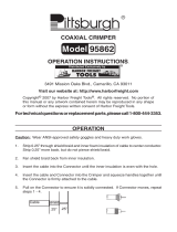
3. Insert the large rubber grommet into the metal cable cutout and slide
the cable cutout w/ grommet into the slot on the bottom of the
weatherproof box. Secure with the two 1/4 X 20 machine screws and
locking nuts provided. See Figure 4.
4. Insert the two smaller grommets into the two holes adjacent to the
cable cutout.
5. Remove the backing from the plastic wire holder. Locate a position on
the opposite side of the case from the cable cutout approximately 3/4-
inch from and parallel with the front and 2.5 inches from the outside
edge. Press the holder into position.
When installing the ground straps, be sure they are
dressed in such a way that they will not get pinched
between the mounting plate and the weatherproof box
when the shock absorbers are fully compressed.
NOTE
6. Install the four 4-inch radio ground straps (provided) with the
weatherproof case mounting screw through the ring terminal. The flat
side of the ring terminal should be face down.
27
Figure 19. Power Control Cable Outline Diagram

26
HEADSET OPTION INSTALLATION
Headset option includes the helmet-mounted microphone, amplifier belt,
and cables with quick disconnect connectors. A typical installation is
shown in Figure 18.
Install the headset option according to the manufacturer's instructions
provided with the option.
Figure 18. Typical Headset Installation
11
SERVICE TIP
After installation, force full compression of the shock
absorbers and observe the ground straps. If necessary
redress the ground straps to a position that allows full
compression without pinching. (Clearance is reduced
from 5/8” to approximately 1/4”.)
BRAIDED GROUND
RADIO
GROUND
CABLE
WIRE GUIDE
REAR MOUNT
ANTENNA OPTION
STRAP. ( USED IN TOP
POWER LEAD
ENTRANCE
CONTROL
ENTRANCE
MOUNT APPLICATIONS
ONLY)
Figure 4. Weatherproof Box Assembly

12
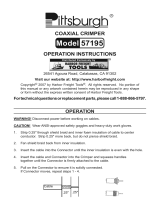
Installing The Weatherproof Box
1. Install the weatherproof case base mounting bracket (19C337200G1)
to the motorcycle mounting bracket (customer supplied and installed)
with the four 1/4 X 20 X 3/4 inch cap screws and lock nuts provided.
See Figure 5.
If the Rear Mount Antenna Option is used, refer to the
antenna installation procedures and install the antenna
mounting bracket now.
NOTE
2. Mount the weatherproof box to the mounting base (19C337200G1)
using the six 1/4-20 x 3/4-inch cap screws and locknuts provided.
Position the weatherproof box so that the cable access cutout is
towards the front of the motorcycle.
When using the recommended antenna ground strap,
(top mount applications only) install the end of the
braided and sleeved ground strap with the small terminal
under the center rear bolt head as shown in Figure 4.
NOTE
3. Install the bottom mounting plate, 19D903778P1, using the four 10 x
32 screws and washers supplied. Refer to Figure 6 to view an
assembled unit. When installed correctly, the mounting plate will be
approximately centered, side-to-side, in the weatherproof box. The lips
on the mounting plate will be face down, the rubber pad is topside.
Figure 5. Weatherproof Box Mounting
25
Figure 17. Radio Connections

24
Figure 16. Antenna Mounting (Rear Mount Option)
FINAL CHECKS AND CONNECTIONS
After the weatherproof case is installed and all cables run, connect the
power/control plug to the radio, connect the antenna to the radio, and
connect the cable shield ground to the radio case with the metric screw
provided with the Power/Control Cable as shown in Figure 17, Radio
Connections.
Make a final check of all cables to make sure they are properly connected
and dressed away from all moving parts and exhaust pipes, and secured
with cable ties. Then recheck all electrical connections and radio mounting
hardware.
To ensure optimum performance, make sure the cable
shield ground lead is connected to the radio case.
NOTE
SERVICE NOTE: Refer to the control unit maintenance manual for the
required initial adjustments.
13
Figure 6. Radio Top Mounting Bracket Installation
If you are installing a radio that has not been modified
for motorcycle applications, refer to “Radio
Modification Procedures” and modify the radio before
continuing.
NOTE
4. Refer to Figure 7 and position the radio and top mounting plate
assembly over the bottom mounting plate. Align the holes in the two
mounting plates (two on each side) and secure with the four machine
screws (N30AP16010), lockwashers (N406P39), and (N400P9) flat
washer provided. Secure the spade lugs of the 4-inch grounding straps
between screws (N30AP16010) and mounting plates.
When installing the ground straps, be sure they are
dressed in such a way that they will not get pinched
between the mounting plate and the weatherproof box
when the shock absorbers are fully compressed.
NOTE
5. If an optional rear-mount antenna is not used, install the supplied
grommet in the cable entrance cover plate and insert 1/4-20 x 3/4"
screw, flat washer, and nut to seal the grommet.

14
Figure 7. Radio and Base Plate Mounting
Radio Modification Procedures
Applies only to radios that have not been modified for
motorcycle applications.
NOTE
Prior to installing the radio in the weatherproof box, the radio must be
modified to withstand the mechanical vibrations inherent to motorcycle
applications. Refer to Figure 8, RANGR application assembly.
1. Remove and discard standard RANGR mounting screw, spring, and
washer.
2. Remove backing from rubber pad 19B802204P1 and attach to top
mounting plate 19D903777P1 as shown.
3. Remove RANGR bottom cover and four cone shaped mounting feet.
Discard cone shaped mounting feet.
4. Put a small drop of RTV on each end of the receive oscillator crystal to
stake the crystal to the printed board.
5. Assemble RANGR bottom cover and mounting plate 19D903777P1 to
the bottom of the RANGR using four 344A4064P1 screws. Torque to
21 inch-pounds.
6. Remove and discard RANGR top cover.
7. The synthesizer is located under a casting on the top side of the
RANGR radio. Re-torque all screws on the synthesizer casting and
synthesizer printed board to 8.5 inch-pounds.
23
Figure 14. Antenna Mounting (Top Mount Position)
Figure 15. Antenna Modifications

22
ANTENNA INSTALLATION
TOP COVER POSITION
The antenna must be installed in accordance with good engineering
practices for best results. See Figures 14 and 15.
Mount the antenna in the 3/8 inch hole provided in the top of the
weatherproof case according to the antenna manufacturer's instructions
with the following exceptions:
1. Discard the lockwasher provided with the antenna and use the thin
lockwasher provided.
2. The 1/2-inch braided ground strap is required for 29-50 MHz operation
and is recommended for all other bands.
3. For 29-50 MHz, 136-174 MHz, and 450-512 MHz antennas, use the
antenna whip cutting chart provided in this manual (see Table of
Contents). Do not use the cutting chart supplied by the antenna
manufacturer.
When cutting the antenna cable, be sure to have enough slack so that the
case can be opened without straining the antenna cable connections. Route
the antenna cable to the radio along the opposite side of the radio from the
antenna jack and radio heatsink as shown in Figures 2 and 5.
REAR MOUNT OPTION
Mount the antenna on the rear antenna support 19D904965P1 (See Figure
16). Mount the support to the weatherproof case mounting plate using four
1/4-20 x 3/4" cap screws and 1/4-20 locknuts provided. Cover the hole in
the top of the weatherproof case with the plug provided and seal with RTV
compound, if required.
Connect the sleeved, braided ground strap from the rear antenna support to
the motorcycle chassis.
Slip the supplied grommet over the antenna cable and route the antenna
cable through the cable entrance cover plate on the weatherproof box to the
radio.
Connect the ground strap from the rear support bracket to the motorcycle.
15
8. Remove the wire metal handle (if present) from the 13.2 Mhz plug-in
reference oscillator located on the synthesizer board.
9. The logic board in the top of the RANGR radio contains one or two
plug-in crystals. One of these is located under the removable metal
shield. Put a drop of RTV on each end of the crystal to stake the
crystal to the printed board.
Figure 8. RANGR Application Assembly, Bottom View
10. Set the transmitter power to 25 watts (except 30 watts on low band).
The power adjust pot is accessed through a hole in the logic board
adjacent to the synthesizer module.
11. Assemble new RANGR radio top cover 188D5003P1 and torque
screws to 21 inch-pounds.
12 Apply label in vacant recess on the RANGR rear casting.
CABLE INSTALLATION
Cable installation consists of making the power connections, and then
running the radio power/control and vehicle system cables to the control
unit.
To assure the feasibility of the cable routing, it is suggested that the
cables be run before installing the two-way radio. Try to route cables
away from exhaust pipes, mufflers, and moving parts, or where mechanical

16
damage may result. Also, route the cables so that they will not interfere
with the operation of the motorcycle. Secure all cables with black cable ties
for a neat installation.
POWER/CONTROL CABLE
The power/control cable is supplied for negative ground systems only. It is
recommended that the black fuse holder box shipped with the radio be
discarded and the black weatherproof fuse assembly provided be used in
this installation. Also, remove the strain-relief hook from the cable and
install the cable as follows:
Installation Note: Before installing the power/control cable, mount the
weatherproof case as instructed under “Two-Way Radio Mounting”. See
Table of Contents).
1. Remove the two screws securing the cover plate to the cable entrance
hole in the bottom of the weatherproof box. Insert the radio control
cable through the cable entrance hole, leaving the radio connector
inside the weatherproof case (see Figure 9).
2. Split the large grommet provided and install it on the control cable.
Then slide the grommet into the cutout on bottom of the case as shown
in Figure 4. Leave enough slack at the radio end to allow the cable to be
easily connected to the radio, and for the radio to be pulled out of the
case for servicing.
3. Replace the cable entrance cover plate on the weatherproof case.
4. Install the two small grommets in the holes for the power and ground
leads.
5. Cut the terminal off the black ground lead.
6. Cut the red power cable in two and strip the insulation from each of the
cut ends.
7. Run the red and black power leads through the holes in the bottom of
the weatherproof case as shown.
8. Install the black 20-ampere fuseholder using the heat-shrink sleeving
on each side to protect the exposed ends.
9. Run the #8 red and black power leads to the vicinity of the battery.
10. Insert the 20-ampere fuse into the fuseholder. Connect the ring
terminal on the red lead to battery plus (+).
21
SPEAKER MOUNTING
Mount the speaker where the operator can hear it, and where it does not
interfere with the safe operation of the motorcycle. On some motorcycles,
the speaker can be attached to the windshield bracket using existing bolts
to secure the speaker mounting bracket (see Figure 2).
CONTROL UNIT CONNECTIONS
After installing the control unit, speaker, and all cables, connect the
required leads (including option leads) to the vehicle system plug as shown
on the Interconnection Diagram (see the Table of Contents). Then connect
the cables to the control unit connectors as shown in Figure 13.
Figure 13. Control Unit Connections

20
c. Before replacing the fairing, the vehicle system cable and any option
cables may be run under the fairing also. Then replace the fairing by
removing the gas cap, repositioning the fairing, then replacing the
gas cap and the three screws that secure the fairing.
For motorcycle
models not equipped with a gas tank fairing:
After making power connections, run the power/control and vehicle system
cables (as well as any option cables) up the left side of the motorcycle to
the control unit and secure the cables with the cable ties. Note that all
cables connect to the back of the control unit.
MICROPHONE BRACKET
After mounting the control unit and connecting the microphone, mount the
microphone hang-up bracket in a location that is convenient to the
operator, and where it will not interfere with the safe operation of the
motorcycle. For ease of installation, Figure 2 shows the microphone
hang-up bracket mounted on a customer-provided mounting plate.
Figure 12. Cable Routing to the Control Unit
17
11. Install a new ring terminal on the black cable and connect it to battery
minus (-).
Any extra length of the power/control cable can be coiled
under the motorcycle seat and secured to prevent
interference with the operation of the motorcycle. See
Figure 10.
NOTE
Figure 9. Power/Control Cable Installation
Figure 10. Under Seat Cable Installation

18
VEHICLE SYSTEM CABLE
The vehicle system cable provides power to the control unit. The
yellow-fused lead provides the receiver "hot" and transmitter enable
connection. The black lead provides the control unit ground. An optional
red-fused lead (Option CC01) is available for ignition switch standby
control. The vehicle system plug (P1) is used for the speaker and option
connections. The vehicle system cable is shown in Figure 11.
Install the vehicle system cable as follows:
1. Run the cables to the battery area or to Ignition Switch A+. Cut the
cable to the length required.
2. Connect a ring terminal on the end of the lead, if required, and connect
the lead to battery (+).
3. Secure the fused lead to the power/control cable by opening the yellow
fuse assembly and then closing it over the power/control cable and the
black vehicle system cable.
4. Tie down all cables (including option cables) with cable ties.
Figure 11. Vehicle System Cable
19
Installation Notes: Figure 10 shows the use of a customer- fabricated,
under-seat mounting plate. This mounting plate provides mounting
holes and slots for securing connectors, fuses, and cables on some
Harley-Davidson motorcycles (such as model FXRP) . The mounting
plate is especially helpful for large installations.
In addition, banana plugs may be installed in the power cables as
shown in Figure 10 to provide for quick connections to a battery
charger, if desired.
After power connections are made to the power/control and vehicle system
cables, run all of the cables (along with any option cables) to the control
unit using one of the following methods:
For motorcycle models equipped with a gas tank fairing
The cable may be routed from the saddle area, under the fairing, around
the left side of the gas tank filler pipe, and up to the area of the control
unit. The fairing may have to be notched to provide entrance and exit
space. Run the power/control cable as directed in Steps a through c.
a. Remove the three screws securing the fairing-- two at the end nearest
the handlebars and one near the saddle. Next, unscrew and remove
the gas tank cap and lift off the fairing. Replace the gas cap
immediately.
Always replace the gas cap as soon as the fairing is
replaced/removed. This is necessary to reduce the
possibility of an explosion as well as to prevent drill
shavings or other debris from getting into the gas tank
WARNING
b. Run the cables from the saddle area up the left side of the gas tank to
the area of the control unit (see Figure 12).
It may be necessary to notch a portion of the fairing at
the control unit end and at the saddle area to provide
entrance and exit holes for the cable. The entrance and
exit cutaway holes are required to permit the fairing to
be remounted flush to the gas tank.
NOTE

20
c. Before replacing the fairing, the vehicle system cable and any option
cables may be run under the fairing also. Then replace the fairing by
removing the gas cap, repositioning the fairing, then replacing the
gas cap and the three screws that secure the fairing.
For motorcycle
models not equipped with a gas tank fairing:
After making power connections, run the power/control and vehicle system
cables (as well as any option cables) up the left side of the motorcycle to
the control unit and secure the cables with the cable ties. Note that all
cables connect to the back of the control unit.
MICROPHONE BRACKET
After mounting the control unit and connecting the microphone, mount the
microphone hang-up bracket in a location that is convenient to the
operator, and where it will not interfere with the safe operation of the
motorcycle. For ease of installation, Figure 2 shows the microphone
hang-up bracket mounted on a customer-provided mounting plate.
Figure 12. Cable Routing to the Control Unit
17
11. Install a new ring terminal on the black cable and connect it to battery
minus (-).
Any extra length of the power/control cable can be coiled
under the motorcycle seat and secured to prevent
interference with the operation of the motorcycle. See
Figure 10.
NOTE
Figure 9. Power/Control Cable Installation
Figure 10. Under Seat Cable Installation
/