Page is loading ...

THANK YOU
We appreciate the trust and condence you have placed in Hampton Bay through the
purchase of this doorbell buzzer. We strive to continually create quality products designed
to enhance your home. Visit us online to see our full line of products available for your home
improvement needs. Thank you for choosing Hampton Bay!
USE AND CARE GUIDE
DOORBELL BUZZER
Illustrations may vary from actual unit.
Safety Information
Ƒ Please read and understand this entire manual before attempting to assemble, install,
or operate this doorbell.
Ƒ All electrical work must be in accordance with national and local electrical codes. If
in doubt, consult a qualied electrician.
Ƒ This doorbell requires an 8 to 16 volt AC, 10VA transformer.
WARNING: This doorbell requires a low voltage electrical connection. Do not connect directly
to 120V AC.
Care and Cleaning
Ƒ Use a dry cloth to clean the doorbell.
Ƒ Do not use cleaners or polishes.
Ƒ Do not use any uids on the doorbell.
Pre-Installation
TOOLS REQUIRED
Phillips screwdriver Small athead screwdriver Drill
7/32 in. (5.5 mm) Drill bit
Safety goggles
PACKAGE CONTENTS
Part Description Quantity
A Screw 2
B Wall anchor 2
Installation
1
Verifying the transformer
power rating
Power must be supplied from an 8 to 16
volt AC, 10VA transformer.
WARNING: This doorbell requires a
low voltage electrical connection. Do not
connect directly to 120V AC.
2
Removing the existing
doorbell
Remove the cover from the existing
doorbell and label all wires with
masking tape before disconnecting:
Ƒ “F” - Front door push
button wire
Ƒ “T” - Transformer wire
Ƒ “R” - Rear door push button
wire (if applicable)
Disconnect all wires from existing
doorbell and remove doorbell from
mounting surface.
FR
ON
T
REA
R
TRANS
R
T
F
3
Removing doorbell cover
Press down on the doorbell cover
and rotate the cover away from
the doorbell.
4
Mounting the doorbell
Route the wires through the wire
entrance hole in the doorbell.
Place the doorbell against the
wall and mark the two screw hole
locations.
Drill two 7/32 in. pilot holes and
insert the wall anchors.
Attach the doorbell to the mounting
surface using the two screws and
tighten securely.
5
Wiring the doorbell
Connect wire “T” to one of the
screws on the doorbell.
Connect wire “F” (and “R” if
applicable) to the other screw on
the doorbell.
Replace the doorbell cover onto
the doorbell.
Warranty
3-YEAR LIMITED WARRANTY
WHAT IS COVERED
This product is guaranteed to be free of factory defective parts and workmanship for a
period of 3 years from date of purchase. Purchase receipt is required for all warranty
claims.
WHAT IS NOT COVERED
This warranty does not include expendable items (such as light bulbs, batteries, etc.), repair
service, adjustment and calibration due to misuse, abuse or negligence. Unauthorized
service or modication of the product or of any furnished component will void this warranty
in its entirety. This warranty does not include reimbursement for inconvenience, installation,
setup time, loss of use, unauthorized service, or return shipping charges. This warranty
is not extended to other equipment and components that a customer uses in conjunction
with this product.
Contact the Customer Service Team at 1-844-760-3644 or visit www.hamptonbay.com.
Questions, problems, missing parts?
Before returning to the store, call Hampton Bay Customer Service
8 a.m. - 5 p.m., CST, Monday - Friday
1-844-760-3644
HAMPTONBAY.COM
Specications
Power requirements
8 to 16 volt AC, 10VA transformer.
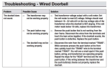
Troubleshooting
Problem Solution
The doorbell does not sound. Test transformer voltage output with a
volt meter. Set the volt meter to read A/C
voltage. Voltage should read between
18 - 22 volts A/C on the low voltage side of
the transformer when the doorbell is NOT
playing. If the volt meter reads below 18
volts, replace the transformer.
Remove the push button that is not working
from the door frame. Disconnect the wires
from the terminals and touch the bare wires
together. If the doorbell sounds, the push
button is defective. Replace the push button.
Disconnect the wire from the terminal
marked “TRANS”. While someone presses
the push button at the front door, quickly
touch the “TRANS” wire to the terminal
marked “FRONT”. You will see a small
spark if the push button, wiring, and
transformer are operating properly. Repeat
the steps for the “REAR” terminal and the
rear push button. If the wiring between the
transformer and the push button(s) checks
out properly, replace the doorbell.
209491-01A
A
B
Item #1003008558
Model #HB-170-03

GRACIAS
Agradecemos la conanza que ha puesto en Hampton Bay por medio de la compra de
este timbre zumbador Procuramos crear continuamente productos de calidad diseñados
para mejorar su hogar. Visítenos en internet para ver nuestra línea completa de productos
disponibles que necesita para el mejoramiento de su hogar. ¡Gracias por escoger Hampton
Bay!
GUÍA PARA EL USO Y CUIDADO
TIMBRE ZUMBADOR
Las ilustraciones pueden ser diferentes de la unidad comprada.
Información de seguridad
Ƒ Por favor lea y entienda todo este manual antes de tratar de ensamblar, instalar u
operar este timbre.
Ƒ Todo trabajo eléctrico debe estar en conformidad con los códigos eléctricos
nacionales y locales. En caso de duda, consulte con un electricista calicado.
Ƒ Este timbre requiere un transformador de 8 a 16 voltios CA, 10VA.
ADVERTENCIA: Este timbre requiere una conexión eléctrica de bajo voltaje. No lo
conecte directamente a 120 VCA.
Cuidado y limpieza
Ƒ Use un paño seco para limpiar el timbre.
Ƒ No use limpiadores o pulidores.
Ƒ No use ningún líquido en el timbre.
Antes de la instalación
HERRAMIENTAS REQUERIDAS
Destornillador phillips Pequeño destornillador
de cabeza plana
Taladro
Broca de 7/16 pulgadas (5,5mm)
Gafas de seguridad
CONTENIDO DEL PAQUETE
Pieza Descripción Cantidad
A Tornillo 2
B Ancla de expansión de pared 2
Instalación
1
Verificación de la potencia
nominal del transformador
La alimentación debe venir de un
transformador de 8 a 16 voltios CA,
10VA.
ADVERTENCIA: Este timbre requiere
una conexión eléctrica de bajo voltaje.
No lo conecte directamente a 120 VCA.
2
Retiro del timbre existente
Retire la tapa del timbre existente
e identique todos los cables
con cinta protectora antes de
desconectarlos:
Ƒ “F” – Cable del botón
pulsador de la puerta
delantera
Ƒ “T” – Cable del transformador
Ƒ “R” – Cable del botón
pulsador de la puerta
posterior (si es aplicable)
Desconecte todos los cables del
timbre existente y retire el timbre de
la supercie de montaje.
FRONT
RE
A
R
TRAN
S
R
T
F
3
Extracción de la cubierta
del timbre
Presione la cubierta del timbre
hacia abajo y gire la cubierta para
alejarla del timbre.
4
Montaje del timbre
Pase los cables por el oricio de
entrada del cable en el timbre.
Coloque el timbre contra la pared
y marque los dos sitios de los
oricios para tornillos.
Taladre dos oricios guía de 7/32
de pulgada e inserte los anclajes
de pared.
Sujete el timbre a la supercie
de montaje con los dos tornillos y
apriételo rmemente.
5
Cableado del timbre
Conecte el cable “T” a uno de los
tornillos en el timbre.
Conecte el cable “F” (y “R” si
corresponde) al otro tornillo en
el timbre.
Vuelva a colocar la cubierta del
timbre sobre el timbre.
Garantía
3 AÑOS DE GARANTÍA LIMITADA
LO QUE SE CUBRE
Se garantiza que este producto no tiene partes defectuosas de fábrica o de mano de obra
por un período de 3 años desde la fecha de compra. Se necesita el recibo de compra para
todos los reclamos de garantía.
LO QUE NO SE CUBRE
Esta garantía no incluye los artículos reemplazables (como bombillas, pilas etc.), servicio
de reparación, ajuste y calibración debido al mal uso, abuso o negligencia. Los servicios no
autorizados o las modicaciones hechas al producto o a cualquier componente invalidarán
esta garantía en su totalidad. Esta garantía no incluye reembolso por inconveniencia,
instalación, tiempo de instalación, perdida de uso, servicio no autorizado, o gastos de envío.
Esta garantía no se extiende a otros equipos o componentes que el consumidor usa junto
con este producto.
Póngase en contacto con el personal de servicio al cliente al 1-844-760-3644 o visite el
sitio www.hamptonbay.com.
¿Tiene preguntas, problemas o piezas faltantes?
Antes de la devolución al almacén llame al Servicio al Cliente de Hampton Bay de
8 a.m.-5 p.m., Hora del Central, de lunes a viernes.
1-844-760-3644
HAMPTONBAY.COM
Especicaciones
Requisitos de la energía eléctrica
Transformador de 8 a 16 voltios CA, 10VA.
Análisis de averías
Problema Solución
El timbre no suena. Pruebe la salida de voltaje del
transformador con un voltímetro. Ajuste
el voltímetro para que lea el voltaje CA.
La lectura del voltaje debería estar entre
18-22 voltios CA en el lado de bajo voltaje
del transformador cuando el timbre NO está
sonando. Si el voltímetro lee menos de 18
voltios, reemplace el transformador.
Retire el botón pulsador que no está
funcionando desde el marco de la puerta.
Desconecte los cables de los terminales
y toque los cables desnudos juntos. Si el
timbre suena, el pulsador está defectuoso.
Reemplace el botón pulsador.
Desconecte el cable del terminal marcado
“TRANS”. Mientras alguien presiona el
botón pulsador en la puerta delantera,
toque rápidamente el cable “TRANS” con el
terminal marcado “FRONT” (DELANTERA).
Verá una pequeña chispa si el botón
pulsador, el cableado y el transformador
están funcionando correctamente. Repita los
pasos para el terminal “REAR” (POSTERIOR)
y el botón pulsador posterior. Si el cableado
entre el transformador y el o los pulsadores
está bien, reemplace el timbre.
209491-01A
A
B
Articulo #1003008558
Modelo #HB-170-03
/


