Powers HydroGuard 447 Infrared Installation guide

Type
Installation guide

Powers HydroGuard 447 Infrared is an automatic shower system that uses infrared technology to detect the presence of a user and dispense water accordingly. It features adjustable sensitivity and run time, allowing for customization based on user preferences. The system includes a sensor assembly, solenoid valve, control box, and mounting hardware for easy installation. It promotes water conservation by shutting off the water flow when the user steps out of the infrared beam or when the maximum shower time is reached.

Powers HydroGuard 447 Infrared is an automatic shower system that uses infrared technology to detect the presence of a user and dispense water accordingly. It features adjustable sensitivity and run time, allowing for customization based on user preferences. The system includes a sensor assembly, solenoid valve, control box, and mounting hardware for easy installation. It promotes water conservation by shutting off the water flow when the user steps out of the infrared beam or when the maximum shower time is reached.

WARNING
!
Hydroguard ESP infrared shower systems rely on infrared
technology to sense the presence of a user and to imme-
diately turn on a water supply. The shower automatically
shuts off when the bather steps out of the invisible beam of
infrared light, or when the maximum shower time has been
reached. The shower time is field adjustable 1 minute 30
seconds to 2 hours and 30 minutes.
All showers are supplied complete with the sensor assem-
bly, box transformer, solenoid valve, control box and
mounting hardware.
The following instructions will serve as a guide when install-
ing the Powers ESP sensor operated showers. As always,
good safety practices and care are recommended when
installing electrical equipment. We suggest that you follow
the procedures outlined. If additional assistance is required,
please call the Powers Application Engineering Department
at (800) 669 5430.
Prior to Installation
WARNING
!
24Vac transformer is used for a single shower application.
Do not allow power transformer wires to touch during wiring, since
this could cause permanent damage to the transformer. To avoid
this, do not supply power to, or plug in, the transformer until all
other wiring is complete.
Since solenoid valves require water free of sand, grit, etc., to
operate properly, flush water lines until water is free of those
materials before connecting solenoid valve.
All electrical wiring and plumbing should be done in accordance
with national/local codes and regulations.
We recommend the use of stainless steel screws for installation
of all components.
TOOLS REQUIRED:
• Slotted and Phillips screwdrivers
• Drill
• Pipewrenches
• Pipe dope/sealing compound
Powers ESP Infrared Showers are supplied with a brass
Solenoid Valve, into which tempered water should be
connected. A Powers thermostatic mixing valve, such
as the Hydroguard Series LFLM495, will ensure safe
comfortable water is supplied to your shower system.
Description
ESP Model 447-10000K100
IS-P-447S
Hydroguard ESP
TM
Infrared Sensor Showers
INSTALLATION INSTRUCTIONS
WARNING
!
Read this Manual BEFORE using this equipment.
Failure to read and follow all safety and use information
can result in death, serious personal injury, property
damage, or damage to the equipment.
Keep this Manual for future reference.
Powers product specifications in U.S. customary units and metric are approximate and are provided for reference only. For precise measurements,
please contact Powers Technical Service. Powers reserves the right to change or modify product design, construction, specifications, or materials with-
out prior notice and without incurring any obligation to make such changes and modifications on Powers products previously or subsequently sold.
Need for Periodic Inspection/Maintenance: This product must
be tested periodically in compliance with local codes, but at least
once per year or more as service conditions warrant. All prod-
ucts must be retested once maintenance has been performed.
Corrosive water conditions, inlet temperatures over 200°F (93°C),
and/or unauthorized adjustments or repair could render the
product ineffective for the service intended. Regular checking
and cleaning of the product’s internal components helps assure
maximum life and proper product function.
Installation
2
Step 1: Determine Shower Component Layout
Several components, including the shower sensor, control box,
solenoid and transformer, will need to be installed to ensure proper
operation of the
infrared shower
system.
The first location to
be identified should
be the shower
sensor… the sen-
sor is housed in a
Stainless Steel Plate
designed for surface
mounting onto the
shower wall. Once
the sensor location
is determined, you
can decide on the
location of the other
components—the
solenoid and sensor
are typically located
within 2 feet of the
control box, but you
can use 4 conductor
flat telephone cable
and connectors to
locate the compo-
nents up to as far as
100' away from the
sensor.
Control box
Sensor
assembly
CL of electrical box:
41 to finished floor
Electrical box
(supplied by others)
Solenoid valve
assembly
Finished
wall
Box transformer
41
Figure 1: Typical Shower Installation
Showerhead &
arm/flange
Piping supplied
by others
The solenoid valve should be located as close as possible to the
showerhead it is servicing. Access to the valve must be provided for
maintenance and servicing.
Suggested height for mounting of the sensor for adult men and
women is approximately 41"… adjustments to height should be
made for adolescents and children. Measure the proper height from
the floor… mark shower sensor location with a pencil. Using a 5/8"
drill bit, drill hole for sensor connection cord.
Once you’ve pushed the shower sensor cord through the hole, use the
stainless steel plate as a template, marking the location of the mount-
ing screws. The shower sensor assembly can be mounted to a 4 x 2
x 23/16" deep electrical box with screws provided, although it is not
necessary to do so. If installing onto wall, drill 2 mounting holes (refer
to figure 2) and install the sensor assembly.
Do not yet tighten screws since you may need access to the
sensitivity and run time potentiometers for final adjustments.
Step 2: Install Solenoid
To facilitate servicing, you may wish to install a service stop directly
upstream of solenoid. Prior to installing solenoid, flush lines to be sure
supply water is free from grit and sand. Solenoid end connections are
3/4" NPT.
Using thread sealant on male threads only (do not use teflon tape),
connect supply line to solenoid, checking to be sure the flow is in the
proper direction (flow arrow is marked on solenoid body). For normal
operation, check to be sure the solenoid manual override is in the
“off” position or water will flow regardless of sensor activation/deac-
tivation.
Connect outlet side of solenoid to showerhead piping.
Step 3: Install Control Box
Keeping in mind that the solenoid and sensor must be within 2 feet
of the control box (unless you’re using extra cables and connectors),
determine the location for mounting. Using the base of the box as
a template (cover should be removed by unscrewing the 4 screws
and taking the cover off), drill two small holes and using two screws
through the holes on the base plate, mount and tighten to the wall.
See figure 3.
Box Mount Transformer (see figure 4). This type of transformer is
designed to be mounted on an 110 VAC supply electrical junction box
(“J” box should be mounted inside chase wall or above ceiling). Run
wires from secondary side of trans-
former to control box enclosure.
To avoid permanent damage to
the transformer, sensor, or sole-
noid valve, do not supply power to
primary side of transformer until
all wiring has been completed.
Connect transformer wire to
power connector. Connect sole-
noid wire, and sensor wire to JP1,
JP2 or JP3 plugs. Secure control
box cover over base and tighten
screws.
3
1
4
1
5
8
5
8
Dia. Hole
3
16
Dia. Hole
2 places
Shower Sensor
Assembly
Mounting Holes
Overall size of
plate: 4
7
8
square
Figure 2
Sensor Assembly Mounting Holes
Box Mount
Transformer
24V AC
Secondary
Figure 4
4.58" (116.3)
2.20" (56.0)
4.00" (101.6)
4.55"
(115.6)
2.00"
(50.8)
Signal feed through
TYP 3 places
Power Connector
Thru hole for
power leads
Power lead hole
through back face
1.00"
(25.4)
4.00"
(101.6)
4.00"
(101.6)
2.58"
(65.5)
4.00"
(101.6)
JP2
JP1JP3
Figure 3 Control Box
3
Step 4: Start Up
Supply power to transformer.
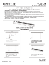
Activate the sensor and check
to be sure the small red activation
light appears in the bottom of
sensor lens. (Refer to figure 5.)
If the light is on, the sensor is
properly operating… turn on
water supply and reactivate sensor. Water should come through
showerhead. Once water is flowing, check all connections for leaks.
Step 5: Sensitivity Adjustment
Shower applications, the Sensor is factory set to provide a proper
sensitivity/distance range for most applications (18≤ from sensor eye,
depending on reflectivity of skin, lighting, etc.).If range is acceptable,
proceed to step 6. If range adjustment is required, you can adjust as
follows.
Remove sensor assembly from wall and look at back side. You’ll see
two potentiometers (see figure 6). The bottom potentiometer is for
adjustment of the range, from 1" to 28". Using the small screwdriver
provided, rotate the potentiometer in small increments: clockwise to
increase the range, counterclockwise to decrease the range. After
each adjustment, check to see if range is acceptable.
Make adjustments carefully. Over-adjustment can damage
potentiometer.
Step 6: Shower Time Adjustment
Although the shower will shut off when bather steps away from the
infrared sensor, the shower can also be set to automatically shut off
after a maximum shower time, from 1 minute 30 seconds to 2 hours
30 minutes. The Sensor Assembly is factory set to provide the shower
time of 14 minutes. If that shower time is acceptable, proceed to
step 7. If shower time adjustment is required, it is easily adjusted
as follows.
Remove sensor assembly from wall and look at back side. You’ll see
two potentiometers (see figure 6): the upper one is for adjustment
of the shower run time from 1 minute 30 seconds to 2 hours 30 min-
utes. Using the small screwdriver provided, rotate the potentiometer
in small increments: clockwise to increase the shower time, counter-
clockwise to decrease the shower time. After each adjustment, check
to see if shower time is acceptable.
Step 7: Secure Sensor Assembly
Once final adjustments have been made to sensitivity and runtime
potentiometers, secure the sensor assembly using the two screws
supplied. We also suggest using plumber’s putty gasket (not sup-
plied) around stainless steel plate to prevent water leakage behind the
wall. To clean, use a mild soap and water, paying special attention to
ensure no abrasive cleaners are used on the lens, since scratching
may occur.
Operation
1. A continuous invisible infrared light beam is emitted from the
sensor assembly.
2. The shower is activated by bather stepping within the adjustable
range of sensor. Immediately after sensor activation, tempered
water flows for as long as the user remains within the range, up to
the set maximum shower time.
3. When the bather steps away from the sensor, the water flow stops
automatically. After preset shower time, the flow of water stops
to prevent water waste. It is then ready for the next user, or for
reactivation by the present user.
Maintenance and Troubleshooting
To clean the shower area but avoid turning off the main water supply,
simply place dark, solid tape (perhaps black electrical tape) on top of
the lens, to block out all light. The sensor should not activate until the
tape is removed. Note that a mild soap may be used to clean the lens,
but abrasive cleaners should be avoided.
To ensure trouble-free performance, routine maintenance is required.
Check all electrical connections, making sure they are free of
corrosion and well connected.
Check solenoid valve to ensure that it is operating properly and is
free of dirt and lime build up.
Check to be sure the tempered water being supplied to the
shower is at the proper temperature for safe comfortable bathing.
If the shower does not function properly:
1. Is the red sensor activation light on in the sensor assembly
lens, upon sensor activation? If red LED is not lit after sensor is
activated,
check to see if transformer feed wires are securely attached to
terminals at modular junction box and at transformer.
check to see if there is power to the transformer, using a
voltmeter. If power is going into the transformer but not coming
out of the transformer, replace transformer.
if transformer is functioning properly and power is being supplied,
replace sensor assembly.
Red
indicator light
Figure 5
Sensor Assembly Activation Ligh
t
Figure 6 Shower Sensor
1
1
2
2
3
3
4
4
A A
B B
APPROVED VENDOR: SLOAN, SAME AS PART NO. EL-462 EXCEPT SENSOR ONLY
1400 EAST LAKE COOK RD
SUITE 180
BUFFALO GROVE, IL 60089
TITLE:
THIS DRAWING DISCLOSES CONFIDENTIAL AN D OTHER DATA OF A PROPRIETARY NATURE OWNED BY
WATTS WATER TECHNOLOGIES, INC. AND MAY NOT BE USED OR DISCLO SED TO OTHERS WITHOUT THE
PRIOR WRITTEN CONSENT OF WATTS WATER TECHNOLOGIES, INC.
DWG BY:
DATE:
SUPERSEDES:SCALE:
CHD BY:
DATE:
R&D:
PART NUMBER:
MATERIAL:
DESCRIPTION:
EDP NO:
FILE TYPE:
REV:
SIZE:
LIMITS UNLESS SPECIFIED
FRACTIONAL ANGULAR
±1/64 ±1/2°
DECIMAL in[mm]
.XXX[0.XX] ±.005[0.13]
.XX[0.X] ±.01[0.3]
COMMON AXIS in[mm]
.015[0.38] TIR
SURFACE FINISH µin[µmeter]
125[3.2] RMS
_________________________
DO NOT SCALE DRAWING
TPD
JPJ
8/10/2006
W
1:1
8/11/2006
444-153 Rev. C
SENSOR ASSEMBLY
H'PANEL INFRARED
SENSOR ASSY., LESS
FACEPLATE
450 555
POWERS
BA
10/24/2008
450-555
A DIVISION OF WATTS WATER TECHNOLOGIES, INC.
REVISION HISTORY
REV ALTERATIONS ALERT DATE BY CHK'D
0 ISSUED NEW 06WP0675 8/10/2006 TPD
-
A
CHANGED +/- ON RANGE AND RUN TIME TO MATCH ACTUAL PART; WAS ON "C" SIZE PAPER
08WP1091
10/24/2008 ERE
JPJ
3.700 [93.98]
INTERFACE CABLE WITH RJ11 PLUG
29.00 ± 0.50 [736.6 ±12.7] LONG, FROM
BACK OF BODY TO PLUG END.
.950
[24.13]
1.024
[26.01]
.580 [14.73]
1.060 [26.92]
(.430 [10.92])
1.32 [33.4]
1.181 [30.00]
59°
2 PLACES
R.25 [6.4]
TYP.
2.200 [55.88]
4.155 [105.54]
3.32 [84.2]
.370 [9.40]
.630 [16.00]
SHOWER SENSOR ASSEMBLY
29.0 [737] OF TRANSMISSION WIRE W/4 WIRE CONNECTOR
POTTED SENSOR WITH I/R LENS.
A
A
IS-P-447S 1713 EDP#6512238 © 2017 Powers
3
1
2
4
USA: T: (800) 669-5430 • F: (847) 229-0526 • PowersControls.com
Canada: T: (905) 332-4090 • F: (905) 332-7068 • PowersControls.ca
Latin America: T: (52) 81-1001-8600 • PowersControls.com
The Seller warrants that the equipment manufactured by it and covered by this order or contract is free from defects in material and workmanship and, without charge, equipment found to be defective in mate-
rial or workmanship will be repaired, or at Seller’s option replaced F.O.B. original point of shipment, if written notice of failure is received by Seller within one (1) year after date of shipment (unless specifically
noted elsewhere), provided said equipment has been properly installed, operated in accordance with the Seller’s instructions, and provided such defects are not due to abuse or decomposition by chemical or
galvanic action. THIS EXPRESS WARRANTY IS IN LIEU OF AND EXCLUDES ALL OTHER WARRANTIES, GUARANTEES, OR REPRESENTATIONS, EXPRESS OF IMPLIED. THERE ARE NO IMPLIED WARRAN-
TIES OF MERCHANTABILITY OR OF FITNESS FOR A PARTICULAR PURPOSE. The Seller assumes no responsibility for repairs made on the Seller’s equipment unless done by the Seller’s authorized personnel,
or by written authority from the Seller. The Seller makes no guarantee with respect to material not manufactured by it.
WARNING: This product contains chemicals known to the
State of California to cause cancer and birth defects or
other reproductive harm.
For more information: Watts.com/prop65
NOTICE
If object is within the range of the Sensor when unit is powered up,
the Sensor will not operate until the object is removed and Sensor
reactivated.
2. If sensor light is lit upon sensor activation, but no water comes
from showerhead,
check to be sure supply line is open and water is being supplied.
check to see whether solenoid is functioning… check to be sure
manual override is in “off≤ position. If system still fails to operate,
repair or replace solenoid assembly (see solenoid repair informa-
tion above).
maximum run time may have been reached… sensor will remain
lit although solenoid will close to stop water from flowing. If
additional shower time is desired, reset run time potentiometer
on back of sensor assembly.
3. If water is on all the time, regardless of sensor activation, unplug
solenoid from control box. If water continues to run, problem is
manual and can be rectified by checking the following:
check for debris and/or lime build-up within the solenoid, which is
preventing it from closing. Dismantle, clean and flush the solenoid
valve.
If, after unplugging solenoid from control box, water stops, problem
is electronic. Check to see if power wires are incorrectly connected
within control box. Refer to instructions above and rewire, checking
electrical connections.
Parts List
No. Description Part No.
1 Sensor Assembly 450-554
2 Solenoid Assembly 444-175
3 Control Box 450-559
4 Box Transformer 444-119
  • Page 1 1
  • Page 2 2
  • Page 3 3
  • Page 4 4

Powers HydroGuard 447 Infrared Installation guide

Type
Installation guide

Powers HydroGuard 447 Infrared is an automatic shower system that uses infrared technology to detect the presence of a user and dispense water accordingly. It features adjustable sensitivity and run time, allowing for customization based on user preferences. The system includes a sensor assembly, solenoid valve, control box, and mounting hardware for easy installation. It promotes water conservation by shutting off the water flow when the user steps out of the infrared beam or when the maximum shower time is reached.

Ask a question and I''ll find the answer in the document

Finding information in a document is now easier with AI