
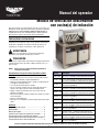
Operator’s Manual
Down Draft Vent Module with Induction Range(s)
©
2018 The Vollrath Company L.L.C. Part No. 2350226-1 ml 3/9/18
Register your product at Vollrath.com/registration and become eligible to win a free 10" Vollrath Tribute
©
fry pan.
Thank you for purchasing this Vollrath equipment. Before operating the
equipment, read and familiarize yourself with the following operating
and safety instructions. SAVE THESE INSTRUCTIONS FOR FUTURE
REFERENCE. Save the original box and packaging. Use this packaging
to ship the equipment if repairs are needed.
SAFETY PRECAUTIONS
To ensure safe operation, read the following statements and understand
their meaning. This manual contains safety precautions which are
explained below. Please read carefully.
Warning is used to indicate the presence of a hazard that will or can
cause severe personal injury or death.
Caution is used to indicate the presence of a hazard that will or can
cause minor or major personal injury if the caution is ignored.
NOTICE: Notice is used to note information that is important but not
hazard-related.
To reduce risk of injury or damage to the equipment:
• Use only grounded electrical outlets matching the nameplate rated
voltage.
• Have the equipment installed by a qualified personnel in accordance
with local codes and ordinances.
• Use the equipment in a flat, level position.
• Do not use an extension cord with this equipment. Do not plug this
equipment into a power strip or multi-outlet power cord.
• Unplug the equipment, turn off and let it cool before cleaning or
moving.
• Do not spray controls or outside of the equipment with liquids or
cleaning agents.
• Do not operate unattended.
• Do not operate if the equipment has been damaged or is
malfunctioning in any way.
FUNCTION AND PURPOSE
This equipment is intended for cooking food and removing grease-
laden air. It includes integrated fire suppression. It is intended for use in
commercial foodservice operations only. It is not intended for
household, industrial or laboratory use. No other use is recommended
or authorized by the manufacturer or its agents.
Table of Contents
System Overview ........................................................ 2
Unpacking ................................................................... 3
Setting Up the Equipment ........................................... 3
Fire Suppression System Installation .......................... 4
Downdraft Vent Operation ........................................... 5
Fire Suppression System Operation ............................ 7
Induction Range Operation ......................................... 8
WARNING
CAUTION
Item No. Description
9718C-1-VCL V-Class Custom, 18" Food Guard, 1-Hob, Operator Left
69718C-1-VCR V-Class Custom, 18" Food Guard, 2-Hob, Operator Right
69718C-2-VC V-Class Custom, 18" Food Guard, 2-Hob
69722C-1-VCL V-Class Custom, 22" Food Guard, 1-Hob, Operator Left
69722C-1-VCR V-Class Custom, 22" Food Guard, 1-Hob, Operator Right
69722C-2-VC V-Class Custom, 22" Food Guard, 2-Hob
69718C-1-SL Signature Server
®
, 18" Food Guard, 1-Hob, Operator Left
69718C-1-SR Signature Server
®
, 18" Food Guard, 1-Hob, Operator Right
69718C-2-S Signature Server
®
, 18" Food Guard, 2-Hob
69722C-1-SL Signature Server
®
, 22" Food Guard, 1-Hob, Operator Left
69722C-1-SR Signature Server
®
, 22" Food Guard, 1-Hob, Operator Right
69722C-2-S Signature Server
®
, 22" Food Guard, 2-Hob

2 Down Draft Vent Module with Induction Range(s) Operator’s Manual
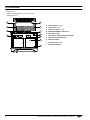
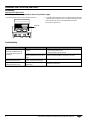
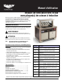
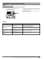
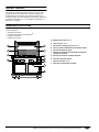
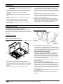
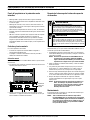
SYSTEM OVERVIEW
The Downdraft Vent Module consists of three integrated systems:
• Downdraft Vent
• ANSUL
®
R-102 Restaurant Fire Suppression System
• Cooking Appliance(s)
F
E
G
H
I
J
A
B
A
C
D
A Discharge Nozzles (4 total)
B Grease Filters (2 total)
C Grease Tray Location (1 total)
D Downdraft Vent Module Control Panel
E Agent Tank Location
F Fire Suppression System Arming View Window
G Induction Range Control Panel(s)
H Manual Pull Station
I Particulate Filters (2 total)
J Downdraft Vent Shroud

Down Draft Vent Module with Induction Range(s) Operator’s Manual 3
UNPACKING
NOTICE: Do not discard the carton or other packing materials until
you have inspected the equipment and tested it for proper
operation.
1. Remove all packing material and tape, as well as any protective
plastic from the equipment. When no longer needed, dispose of all
packaging and materials in an environmentally responsible manner.
2. Clean any glue residue left over from the plastic or tape.
3. Read and understand all labels and diagrams installed on
equipment.
4. Carefully check for and account for all components and accessories
before discarding packaging materials.
5. Place the Downdraft Vent Module on a stable, level surface.
6. Level the Downdraft Vent Module. The included adjustable legs can
be used to level the Downdraft Vent Module or align it with other
equipment. Leg length is adjusted by rotating the leg. Adjust each
leg until the Downdraft Vent Module sets firmly on all legs and is
level front-to-back and side-to-side.
7. If applicable, install the included toe kicks.
8. Ensure a properly grounded electrical supply matching the
nameplate rating is available to the unit.
9. Contact your local ANSUL dealer to install the fusible links, apply
power, test, charge, arm, and commission the ANSUL Fire
Suppression System. Go to ANSUL.com to find a local dealer.
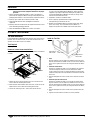
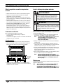
SETTING UP THE EQUIPMENT
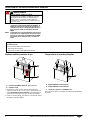
Toe Kick Installation
If your Downdraft Vent Module includes toe kicks, they will need to be
installed. There are four toe kicks, one for each side of the base. The
operator side toe kick is open in the middle.
Tools Required
Right-angle drill
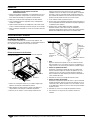
Remove or Loosen Screws from the Base
The V-Class base is illustrated. Installation on a Signature Server
®
base
is similar.
1. Remove the corner screws from the base. There are two in each
corner. Retain for installing the toe kicks.
2. On the operator and customer sides of the base, remove the screw
adjacent to the corner. Retain for installing the toe kicks.
3. Loosen the remaining screws – two on each side of the base.
Install the Toe Kicks
1. Install the customer side toe kick:
Align the notches on the toe kick to the middle screws on the base.
Slide the toe kick onto the middle screws. Insert the screws adjacent
to the corner. Tighten the screws just enough to hold the toe kick in
place.
2. Install the end toe kicks:
Position the end of the toe kick so it is overlapped by the customer
side toe kick. Align the notches on the toe kicks to the middle
screws. Tighten the screws just enough to hold the toe kick in place.
Follow the same process to install the other toe kick to the other end
of the base.
3. Reinstall and tighten the corner screws on the customer side of the
base.
4. Install the operator side toe kick:
Position the end of the toe kick so it is overlaps the end toe kicks.
Align the notches on the toe kick to the middle screws on the base.
Slide the toe kick onto the middle screws. Insert the screws adjacent
to the corner. Tighten the screws just enough to hold the toe kick in
place.
5. Reinstall and tighten the corner screws on the operator side of the
base.
6. Tighten all screws until the toe kicks are securely installed.
Loosen
Loosen
Remove
Loosen
Remove
Loosen
Remove
Remove
Align notches
with screws
Alignnotches
with screws
Overlap
corners

4 Down Draft Vent Module with Induction Range(s) Operator’s Manual
FIRE SUPPRESSION SYSTEM INSTALLATION
NOTICE: The ANSUL Fire Suppression System must be charged by
an authorized ANSUL representative. The Downdraft Vent
Module will not operate and cooking appliance will not be
energized until the ANSUL Fire Suppression System has
been charged.
NOTICE: It is the installer’s responsibility to verify that this
equipment installation is in compliance with the
specifications listed in this manual, ANSUL
documentation, local code requirements, and NFPA
standards.
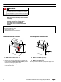
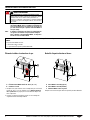
Fusible Links and Gas Cartridges
1. Replace the four temporary test links with the supplied 165°F SL
Fusible Links. Refer to Particulate Filter Replacement on page 6 for
instructions for removing the particulate filters.
2. Install the CO
2
or nitrogen cartridges onto the ANSUL automatic
release/bracket assembly.
Fire Extinguishing Tank and Nozzles
Fill the agent tank with ANSULEX low pH Liquid Fire Suppressant.
WARNING
Fire, Injury, Death Hazard
This equipment must installed and adjusted by a qualified
technician in accordance with all federal, state and local codes.
Failure to install adjust or maintain this equipment properly can
result in property damage, injury or death.
The following instructions are for use only by authorized ANSUL representatives. Refer to ANSUL documentation for the following steps.
ANSUL representative to supply:
•CO
2
or nitrogen cartridge
• ANSULEX Low pH Liquid Fire Suppressant
A ANSUL Model SL Fusible Link 165° F
B LT-20-R Cartridge
B
A
A
A
A ANSUL R-102 1W Nozzle (Appliance)
B ANSUL R-102 1W Nozzle (Duct)
C ANSUL R-102 1¹⁄₂ Gallon Tank
B
A
C
A
B

Down Draft Vent Module with Induction Range(s) Operator’s Manual 5
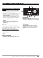
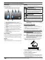
DOWNDRAFT VENT OPERATION
Overview
The Downdraft Vent Module control panel will be operational only
when:
• The ANSUL Fire Suppression System is charged.
• The grease filters and the particulate filters are in position.
Operation
1. Press the Main Power switch to the ON position.
2. Press and release the momentary System Start switch.
3. When the Low indicator light is no longer illuminated, you can begin
using the induction hob(s) for cooking.
Shutdown
1. Turn off the cooking appliance.
2. Press the Main Power switch to the OFF position.
Cleaning
Clean your Downdraft Vent Module daily.
NOTICE: Do not use abrasive materials, scratching cleansers or
scouring pad to clean the unit. These can damage the finish.
Wipe the Equipment Exterior
1. Wipe the equipment exterior.
2. Unplug the equipment and let it completely cool.
3. Use a clean damp cloth. If needed, use a mild soap only.
4. Thoroughly wipe off any mild soap. Residue could corrode the
surface of the unit.
Wash grease filters, grease tray and downdraft vent shroud
NOTICE: Failure to install grease tray will allow grease and
moisture from grease tray to drop into the vent, creating
both a safety hazard and a health hazard
NOTICE: DO NOT wash particulate filters. Washing will clog the
filter and cause the cooking appliance to be disabled. Dirty
particulate filters must be replaced. See Maintenance on
page 6.
1. Remove the grease filters, grease tray and downdraft vent shroud.
Components lift off. No tools are required.
2. Empty the grease tray into an appropriate grease collection
receptacle.
3. Wash the components in a dish washing machine or in a sink with
mild detergent and warm water.
4. Rinse the components with clean water.
5. Dry the components with a clean non-abrasive cloth.
6. Re-install the components.
7. Visually inspect the four discharge nozzles. Verify the nozzle caps
are in place. Contact your local ANSUL authorized representative if
the caps are missing and/or the nozzles need to be repositioned.
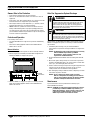
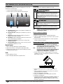
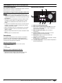
A Main Power Light. Indicates power to the Downdraft Vent
Module is ON.
B Vent Light. Indicates the downdraft vent is ON.
C Low Light. Troubleshooting light. Indicates a filter is missing,
installed incorrectly or is the wrong filter.
D High Light. Troubleshooting light. Indicates the filters are dirty
or are the wrong filter for this unit.
E System Start Switch. Switches ON the downdraft vent.
F Main Power Switch. Switches the Downdraft Vent Module ON
or OFF.
main power
system start low high
when illuminated~
check for missing
or wrong lter(s)
when illuminated~
check for dirty or
wrong lter(s)
BA C D
EF
WARNING
Electrical Shock Hazard
Keep water and other liquids from entering the inside of the
equipment. Liquid inside the equipment could cause an
electrical shock. Do not spray water or cleaning products.
Liquid could contact the electrical components and cause a
short circuit or an electrical shock.
CAUTION
Burn Hazard
Do not touch hot liquid or heating surfaces while unit is
heating or operating.
Hot liquids and food can burn skin. Induction heating surfaces heat
very rapidly. Allow the heating surface to cool before handling.

6 Down Draft Vent Module with Induction Range(s) Operator’s Manual
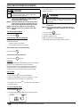
DOWNDRAFT VENT OPERATION (CONTINUED)
Maintenance
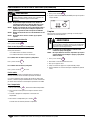
Particulate Filter Replacement
NOTICE: Replace filters every six months or sooner if they become clogged.
1. Remove the grease filters to access the particulate filters. 2. To install a replacement filter, note the air flow direction arrow on the
particulate filter. Position the filter so the airflow arrow points down.
3. Place the filter into the base of the downdraft vent shroud.
4. Re-install the grease filters.
Troubleshooting
Particulate
filter
Problem Might be Caused By Course of Action
Downdraft Vent Module will not
operate. Main Power light is not
illuminated.
No power.
• Reconnect to electrical power.
• Reset circuit breaker for unit.
• Contact Vollrath Technical Services.
ANSUL Fire Suppression System not
properly commissioned or in need of
service.
Contact an authorized ANSUL representative for repair.
Low indicator light illuminated and
cooking unit will not turn on.
Particulate or grease filters not in
position, missing or incorrect type.
Properly install correct filters.
High indicator light illuminated and
cooking unit will not turn on.
Particulate or grease filters dirty or
incorrect type.
Install correct clean filters.

Down Draft Vent Module with Induction Range(s) Operator’s Manual 7
FIRE SUPPRESSION SYSTEM OPERATION
NOTICE: Please refer to the included ANSUL Owner’s Guide for more detailed information.
Owners Role in Fire Protection
• Keep all kitchen equipment free of grease build-up.
• Never use or store flammable solvents or cleaners on or near the
equipment.
• Keep utensils, pots, pans cooking material, etc., stored in areas that
do not obstruct the Fire Suppression System discharge.
• Never tamper with the system components (i.e., detectors, nozzles,
agent storage container(s), releasing mechanism).
• DO NOT remove or reposition the nozzles. All nozzles have been
factory installed and aligned in the proper operating position. Be
sure that all nozzles have nozzle caps assembled to them. Contact
your local ANSUL authorized representative if caps are missing and/
or nozzles need to be repositioned.
Controls and Operation
In the unlikely event of a fire:
• The integrated ANSUL Fire Suppression System will automatically
deploy.
• Power to the cooking appliance and the entire Downdraft Vent
Module will be shut off.
Manual Activation
The ANSUL Fire Suppression System can also be manually activated.
1. Pull the ring on the red manual pull station with enough force to
activate the ANSUL Fire Suppression System.
2. When the ANSUL Fire Suppression System is manually activated,
power to the cooking appliance and the entire Downdraft Vent
Module will shut off.
After Fire Suppression System Discharge
After discharge, the Downdraft Vent Module will not operate until the
ANSUL Fire Suppression System is serviced by an authorized ANSUL
representative.
1. Immediately after discharge, call your authorized ANSUL
representative to inspect and recharge the ANSUL Fire Suppression
System.
NOTICE: The ANSUL Fire Suppression System must be serviced by
authorized ANSUL representative per ANSUL
documentation, and in accordance with local code
requirements and NFPA standards.
2. Clean the Downdraft Vent Module and surrounding area within 24
hours.
3. Wear rubber gloves during cleanup as sensitive skin may become
irritated. If the ANSULEX agent or its residue comes in contact with
skin or eyes, flush thoroughly with clean water.
4. Remove as much of the agent as possible using hot soapy water and
sponges or clean rags. Dispose of sponges or rags in a local
sanitary land fill site in accordance to local regulations.
5. After thoroughly cleaning all affected surfaces, adequately rinse with
clean water. Dry with a soft cloth.
NOTICE: The Fire Suppression System agent is non-toxic.
However, food product and cooking grease/oil that has
come in contact with the agent will no longer be suitable
for human consumption and should be discarded.
Maintenance
System maintenance must be performed semi-annually by an
authorized ANSUL distributor.
NOTICE: All ANSUL Fire Suppression System maintenance must be
performed by an authorized ANSUL representative, per
ANSUL documentation, and in accordance with local code
requirements and NFPA standards. Contact your local
ANSUL representative for maintenance details.
Manual
pull station
WARNING
Electrical Shock Hazard
Keep water and other liquids from entering the inside of the
equipment. Liquid inside the equipment could cause an
electrical shock. Do not spray water or cleaning products.
Liquid could contact the electrical components and cause a
short circuit or an electrical shock.
CAUTION
Burn Hazard
Make certain all surfaces to be cleaned have cooled down to
room temperature. Do not use water to clean any appliances
that contain hot grease or cooking oils. Doing so may result in
violent steaming and/or spattering.

8 Down Draft Vent Module with Induction Range(s) Operator’s Manual
INDUCTION RANGE OPERATION
For Your Safety
These precautions should be followed at all times. Failure to follow
these precautions could result in injury to yourself and others.
To reduce risk of injury or damage to the unit:
• As a precaution, persons using a pacemaker should stand back 12"
(30 cm) from an operating unit. Studies have shown that the
induction element will not disrupt a pacemaker.
• Keep all credit cards, driver licenses and other items with a magnetic
strip away from an operating unit. The unit’s magnetic field will
damage the information on these strips.
• The heating surface is made of a strong, non-porous material.
However, should it crack or break, stop using and immediately
unplug the unit.
• Do not leave an empty pan on an operating unit.
• Do not touch the cooking surface. It remains hot after the unit is
turned off.
• Do not place any objects inside the air intake or exhaust panels.
• Do not place weight on the control knob.
Overview
This equipment is intended for use in commercial food service
operations only. It is not intended for household, industrial or
laboratory use. It is intended to be used with induction-ready cookware.
Induction-Ready Cookware
• Flat base measuring 4¹⁄₂" (11.4 cm) to 10¼" (26 cm) wide
• Ferrous stainless steel
• Iron
• Cast iron
Unsuitable Cookware
• Cookware with a base less than 4¹⁄₂" (11.4 cm)
• Pottery, glass, aluminum, bronze or copper cookware
• Cookware with any type of footed base
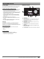
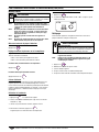
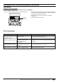
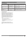
Features and Controls
A On/Off Button.
B Power/Temp Button. Press to toggle between power level (1-
100) and temperature control, and Fahrenheit and Celsius.
C Timer Button. Starts the timer.
D Control Knob. Selects the temperature, power level or time,
depending on the mode.
E ºF and ºC LEDs. Illuminate to indicate which temperature is
displaying.
F Display Panel. Displays the power level, temperature, timer
time or an error code.
G Timer LED Light. Illuminates when timer function is operating.
POWER
TEMP
TIMER
Timer
°F
°C
A B C D
E
F G

Down Draft Vent Module with Induction Range(s) Operator’s Manual 9
INDUCTION RANGE OPERATION (CONTINUED)
Operation
NOTICE: Do not preheat empty cookware. Because of the speed and
efficiency of the induction range, cookware can very
quickly overheat and be damaged.
NOTICE: Do not drop cooking utensils or other objects onto the
cooking surface. The strong, non-porous surface will
break. The warranty does not cover this type of abuse.
NOTICE: Do not leave an empty pan on an operating unit.
NOTICE: Do not heat sealed cans or containers as they may
explode.
Turn On the Induction Range
Press and release .
Adjust the Power Level or Temperature
Increase or decrease
Rotate the control knob.
• Clockwise increases the numbers.
• Counterclockwise decreases the numbers.
Switch between power and temperature modes
Press and release .
Switch between Fahrenheit and Celsius
Press and release two times.
Cook Food
The display should remain constant during operation. If the display is
flashing, see the Troubleshooting section in this manual.
Removing cookware from the cooking surface for more than ten
minutes will cause the unit to automatically turn off. Removing
cookware for less than ten minutes will not interrupt operation.
Use the Timer
1. Press and release . The timer LED will flash.
2. Rotate the control knob to set the time in full minutes (1-180).
3. When the timer cycle is complete, the range turn off.
4. To cancel the timer, press . The range will return to power or
temperature mode.
Turn off the Induction Range
1. Press and release .
2. The control panel will display HOT until the surface has cooled.
Cleaning
To maintain the appearance and increase the service life, clean your
induction range daily.
NOTICE: The cooking surface remains hot even when this equipment
is turned off.
NOTICE: Do not use abrasive materials, scratching cleansers or
scouring pads to clean the equipment. These can damage
the finish.
1. Press and release .
2. Unplug the cord from the wall outlet.
3. Allow the equipment to cool.
4. Wipe the exterior with a clean damp cloth.
5. Thoroughly wipe off any mild soap or chemical cleaners.
CAUTION
Burn Hazard
Do not touch hot food, liquid or heating surfaces while
equipment is heating or operating.
POWER
TEMP
POWER
TEMP
TIMER
TIMER
WARNING
Electrical Shock Hazard
Do not spray water or cleaning products. Liquid could contact
the electrical components and cause a short circuit or an
electrical shock.

10 Down Draft Vent Module with Induction Range(s) Operator’s Manual
INDUCTION RANGE OPERATION (CONTINUED)
Troubleshooting
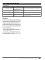
FCC Statement
This equipment has been tested and found to comply with Part 18 of
FCC Rules. These limits are designed to provide reasonable protection
against harmful interference in a residential installation. This equipment
generates, uses and can radiate radio frequency energy and, if not
installed and used in accordance with the instructions, may cause
harmful interference to radio communications. However, there is no
guarantee that interference will not occur in a particular installation. If
this equipment does cause harmful interference to radio or television
reception, which can be determined by turning the equipment off and
on, the user is encouraged to try to correct the interference by one or
more of the following measures:
• Reorient or relocate the receiving antenna
• Increase the separation between the equipment and receiver
• Connect the equipment into an outlet on a circuit different from that
to which the receiver is connected
• Consult the dealer or an experienced radio/TV technician for help
To assure continued compliance, any changes or modifications not
expressly approved by the party Responsible for compliance could void
the user’s authority to operate this equipment.
Problem Might be Caused By Course of Action
The unit turned off after 10 minute(s).
There is not a pot/pan on the induction
range or the pot/pan is not induction-
ready cookware. The induction range
turned off. This is normal.
Make sure the pot/pan is induction ready. See “Overview” on
page 8.
The unit is on, but not heating.
The cookware may be too small or may
not be induction-ready.
Make sure the pot/pan is induction ready. See “Overview” on
page 8.
The digital display is flashing F2.
The overheat-protection feature may
have activated.
Remove cookware. Let cooking surface cool.
The unit suddenly stopped working.
The unit may be too close to an external
heat source or the air intake may be
restricted.
Relocate the unit away from any external heat source. Clear any
obstructions to the air intake.

Down Draft Vent Module with Induction Range(s) Operator’s Manual 11
This page intentionally left blank.

©
2018 The Vollrath Company L.L.C. Part No. 2350226-1 ml 3/9/18
www.vollrath.com
The Vollrath Company, L.L.C.
1236 North 18th Street
Sheboygan, WI 53081-3201 U.S.A.
Main Tel: 800.624.2051 or 920.457.4851
Main Fax: 800.752.5620 or 920.459.6573
Customer Service: 800.628.0830
Canada Customer Service: 800.695.8560
Technical Services
Induction Products: 800.825.6036
Countertop Warming Products: 800.354.1970
All Other Products: 800.628.0832
SERVICE AND REPAIR
Serviceable parts are available on Vollrath.com.
To avoid serious injury or damage, never attempt to repair the unit or replace a damaged power cord yourself. Do not send units directly to
The Vollrath Company LLC. Please contact Vollrath Technical Services for instructions.
When contacting Vollrath Technical Services, please be ready with the item number, model number (if applicable), serial number, and proof of
purchase showing the date the unit was purchased.
WARRANTY STATEMENT FOR THE VOLLRATH CO. L.L.C.
This warranty does not apply to products purchased for personal, family or household use, and The Vollrath Company LLC does not offer a written
warranty to purchasers for such uses.
The Vollrath Company LLC warrants the products it manufactures or distributes against defects in materials and workmanship as specifically
described in our full warranty statement. In all cases, the warranty runs from the date of the end user’s original purchase date found on the receipt.
Any damages from improper use, abuse, modification or damage resulting from improper packaging during return shipment for warranty repair will
not be covered under warranty.
For complete warranty information, product registration and new product announcement, visit www.vollrath.com.
ANSUL components are warranted by ANSUL. For details please visit www.ansul.com.
ANSUL
®
is a registered trademark of Tyco Fire Protection Products.
Page is loading ...
Page is loading ...
Page is loading ...
Page is loading ...
Page is loading ...
Page is loading ...
Page is loading ...
Page is loading ...
Page is loading ...
Page is loading ...
Page is loading ...
Page is loading ...
Page is loading ...
Page is loading ...
Page is loading ...
Page is loading ...
Page is loading ...
Page is loading ...
Page is loading ...
Page is loading ...
Page is loading ...
Page is loading ...
Page is loading ...
Page is loading ...
-
 1
1
-
 2
2
-
 3
3
-
 4
4
-
 5
5
-
 6
6
-
 7
7
-
 8
8
-
 9
9
-
 10
10
-
 11
11
-
 12
12
-
 13
13
-
 14
14
-
 15
15
-
 16
16
-
 17
17
-
 18
18
-
 19
19
-
 20
20
-
 21
21
-
 22
22
-
 23
23
-
 24
24
-
 25
25
-
 26
26
-
 27
27
-
 28
28
-
 29
29
-
 30
30
-
 31
31
-
 32
32
-
 33
33
-
 34
34
-
 35
35
-
 36
36


Ask a question and I''ll find the answer in the document
Finding information in a document is now easier with AI
in other languages
- français: Vollrath 69722C-2-S Manuel utilisateur
- español: Vollrath 69722C-2-S Manual de usuario
Related papers
-
Vollrath Induction Range, Commercial, Countertop User manual
-
-
-
-
Vollrath Medium Power Countertop Induction Ranges User manual
-
-
-
-
-
Other documents
-
 Ansul R-102 Owner's manual
-
 Ansul PIRANHA Owner's manual
-
Wells WVG-136 Operating instructions
-
Wells WV-FGRW Operating instructions
-
Wells Manufacturing WV-4HFRWT Operating instructions
-
Wells Manufacturing WVF-886RW Operating instructions
-
-
-
-
Wells Manufacturing WV-2HFG Operating instructions

