Page is loading ...

ASSEMBLY INSTRUCTIONS
If operating pressures exceed 5 BAR (~75 PSI), the use of a pressure
reducer is recommended. Before proceeding with the assembling, we
advise to clean the hot and cold water tubes, in order to avoid that
build-up of dirt could compromise the functioning of the faucet.
For politics of mutual improvement, the suppli
er reserves the right
to make revisions in product specifications without notice, therefore
the images and data contained in this instruction sheet have to be
considered as indicative.
FAUCET INSTALLATION (Fig.1)
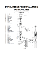
Assemble the threaded pins (2) and the supply tubes (3) in the faucet
body (1). Insert the base ring (3) and the o-ring (4), place everything
in the hole of the sanitary. Verify the correct position of the o-ring (4).
Slip the C-washer (7) and the flange (8) in the threaded pins (5),
then fix the faucet with the nuts (9). Connect the supply tubes (6):
the left one to the hot water supply and the right one to the cold
water supply. Open the water supply and verify both the correct
functioning of the faucet and the sealing of all the parts.
M
OUNTING THE DRAIN (Fig.11.) (only for art.211)
Insert the drain (15) with the tapered seal in the waste hole (if
necessary use sealant between drain and ceramic) then fix using the
nut (19) placing the washer (17) and the flange (18) in between.
Screw the vertical sleeve (22) to the waste body (21) and all this to
the drain, placing the washer (20) in between. Place the horizontal
rod (10) positioning the piece (13) as shown in the figure, then fix with
the nut (12). Insert the waste rod (1) with knob in its proper hole
of the faucet, connect it to the drain rod through the clamp (11) then
regulate the run of the drain cap (14).
MAINTENANCE AND TECHNICAL-PRACTICAL SUGGESTIONS
REPLACEMENT OF THE CARTRIDGE
(shut off the main water supply) (Fig.2)
Take out the lever (1), unscrew the cap (5) and the locking nut (6)
then take out the cartridge (7). Assemble it in the new cartridge, proceed
in reverse order to assemble, mind to clean the surfaces in contact
with the sealing washers. Close the nut (6) in such a way to grant
the sealing and in the meantime to allow that the handle turns smoothly.
CLEANING THE AERATOR (Fig.3)
It is advisable to clean the aerator periodically, in order to avoid
build-up of dirt and limestone, which in time could gradually limit the
water flow. To disassemble the aerator (1), unscrew it and clean the
filter (2) from all impurities, reassemble by proceeding in the reverse
order making sure the gasket (3) is correctly placed.
MAINTENANCE OF THE SURFACES
During the cleaning, the surface of the
faucet has to be cold (as hot
speeds up the wearing out of the surface). Make sure that cleaning
products do not contain acids or corrosive substances. The faucet
has to be daily dried with a soft cloth. Avoid steel wool, abrasive
sponges or similar. Soon after cleaning, wash away the residue of
cleaning lotions with cold water. Damages to faucets following from
a not appropriate treatment will invalidate your guarantee.
Fig.1
Fig.2 Fig.3
GB
Supply Recommended Max. Min.
Hot water temperature 65 C° (~150F) 80 C° (~175F) 15 C° (~60F)
Operating pressure 3 BAR (~45PSI) 5 BAR (~75PSI) 0.5 BAR (~7PSI)
Fig.1.1
/


