
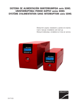
MultiPlus
(with firmware xxxx400 or higher)
MultiPlus (con firmware xxxx400 o superior)
12 | 3000 | 120 - 50 | 120V
(PMP122301102)
24 | 3000 | 70 - 50 | 120V
(PMP242301102)
User Manual
EN
Manual de usuario
ES
Appendix


1
EN ES Appendix
1. SAFETY INSTRUCTIONS
In general
Please read the documentation supplied with this product first, so that you are familiar with the safety signs en directions before using
the product.
This product is designed and tested in accordance with international standards. The equipment should be used for the designated
application only.
WARNING: DANGER OF ELECTRICAL SHOCK
The product is used in combination with a permanent energy source (battery). Even if the equipment is switched off, a dangerous
electrical voltage can occur at the input and/or output terminals. Always switch the AC power off and disconnect the battery before
performing maintenance.
The product contains no internal user-serviceable parts. Do not remove the front panel and do not put the product into operation unless
all panels are fitted. All maintenance should be performed by qualified personnel.
Never use the product at sites where gas or dust explosions could occur. Refer to the specifications provided by the manufacturer of the
battery to ensure that the battery is suitable for use with this product. The battery manufacturer's safety instructions should always be
observed.
WARNING: do not lift heavy objects unassisted.
Installation
Read the installation instructions before commencing installation activities.
This product is a safety class I device (supplied with a ground terminal for safety purposes). Its AC input and/or output terminals
must be provided with uninterruptible grounding for safety purposes. An additional grounding point is located on the outside
of the product. If it can be assumed that the grounding protection is damaged, the product should be taken out of operation and
prevented from accidentally being put into operation again; contact qualified maintenance personnel.
Ensure that the connection cables are provided with fuses and circuit breakers. Never replace a protective device by a component of a
different type. Refer to the manual for the correct part.
Check before switching the device on whether the available voltage source conforms to the configuration settings of the product as
described in the manual.
Ensure that the equipment is used under the correct operating conditions. Never operate it in a wet or dusty environment.
Ensure that there is always sufficient free space around the product for ventilation, and that ventilation openings are not blocked.
Install the product in a heatproof environment. Ensure therefore that there are no chemicals, plastic parts, curtains or other textiles, etc.
in the immediate vicinity of the equipment.
Transport and storage
On storage or transport of the product, ensure that the mains supply and battery leads are disconnected.
No liability can be accepted for damage in transit if the equipment is not transported in its original packaging.
Store the product in a dry environment; the storage temperature should range from –20°C to 60°C.
Refer to the battery manufacturer's manual for information on transport, storage, charging, recharging and disposal of the battery.

2
2. DESCRIPTION
2.1 In general
The basis of the MultiPlus is an extremely powerful sine inverter, battery charger and automatic switch in a compact casing.
The MultiPlus features the following additional, often unique characteristics:
Automatic and uninterruptible switching
In the event of a supply failure or when the generating set is switched off, the MultiPlus will switch over to inverter operation and take
over the supply of the connected devices. This is done so quickly that operation of computers and other electronic devices is not
disturbed (Uninterruptible Power Supply or UPS functionality). This makes the MultiPlus highly suitable as an emergency power system
in industrial and telecommunication applications. The maximum alternating current that can be switched is 16A or 50A, depending on
model.
Auxiliary AC output
Besides the usual uninterruptable output, an auxiliary output is available that disconnects its load in the event of battery operation.
Example: an electric boiler that is allowed to operate only if the genset is running or shore power is available.
Virtually unlimited power thanks to parallel operation
Up to 6 Multis can operate in parallel. Six units 24/3000/70, for example, will provide 15kW / 18kVA output power and 420 Amps
charging capacity.
Three phase capability
Three units can be configured for three-phase output. But that’s not all: up to 6 sets of three units can be parallel connected to provide
45kW / 54kVA inverter power and more than 1000A charging capacity.
PowerControl – maximum use of limited shore current
The MultiPlus can supply a huge charging current. This implies heavy loading of the shore connection or generator set. Therefore a
maximum current can be set. The MultiPlus then takes other power users into account, and only uses 'surplus' current for charging
purposes.
PowerAssist – Extended use of your generator and shore current: the MultiPlus “co-supply” feature
This feature takes the principle of PowerControl to a further dimension allowing the MultiPlus to supplement the capacity of the
alternative source. Where peak power is so often required only for a limited period, the MultiPlus will make sure that insufficient shore or
generator power is immediately compensated for by power from the battery. When the load reduces, the spare power is used to
recharge the battery.
This unique feature offers a definitive solution for the ‘shore current problem’: high power electric tools, dish washers,
washing machines, electric cooking etc. can all run on 16A shore current, or even less. In addition, a smaller generator can be
installed.
Three programmable relays
The relays can be programmed for all kinds of applications, for example as a starter relay for a generating set.
Two programmable analog/digital input/output ports
These ports can be used for several purposes. One application is communication with the BMS of a lithium-ion battery.
Frequency shift
When solar inverters are connected to the output of a Multi or Quattro, the excess solar energy is used to recharge the batteries. Once
the absorption voltage is reached, the Multi or Quattro will shut down the solar inverter by shifting the output frequency 1Hz (from 50Hz
to 51Hz for example). Once battery voltage has dropped slightly, the frequency returns to normal and the solar inverters will restart.
Built-in Battery Monitor (optional)
The ideal solution when Multis or Quattros are part of a hybrid system (diesel generator, inverter/chargers, storage battery, and
alternative energy). The built-in battery monitor can be set to start and stop the generator:
- Start at a preset % discharge level, and/or
- start (with a preset delay) at a preset battery voltage, and/or
- start (with a preset delay) at a preset load level.
- Stop at a preset battery voltage, or
- stop (with a preset delay) after the bulk charge phase has been completed, and/or
- stop (with a preset delay) at a preset load level.
Solar energy
The MultiPlus is extremely suitable for solar energy applications. It can be used in autonomous systems as well as grid connected
systems.

3
EN ES Appendix
Autonomous operation when the grid fails
Houses or buildings with solar panels or a combined micro-scale heating and power plant or other sustainable energy sources have a
potential autonomous energy supply which can be used for powering essential equipment (central heating pumps, refrigerators, deep
freeze units, Internet connections, etc.) during a power failure. A problem is however that grid connected sustainable energy sources
drop out as soon as the grid fails. With a MultiPlus and batteries, this problem can be solved in a simple manner: the MultiPlus can
replace the grid during a power failure. When the sustainable energy sources produce more power than needed, the MultiPlus will
use the surplus to charge the batteries; in the event of a shortfall, the MultiPlus will supply additional power from the battery.
Programmable with DIP switches, VE.Net panel or personal computer
The MultiPlus is supplied ready for use. Three features are available for changing certain settings if desired:
─ The most important settings (including parallel operation of up to three devices and 3-phase operation) can be changed in a very
simple manner, using DIP switches.
─ All settings, with exception of the multi-functional relay, can be changed with a VE.Net panel.
─ All settings can be changed with a PC and free of charge software, downloadable from our website www.victronenergy.com
2.2 Battery charger
Adaptive 4-stage charging characteristics: bulk – absorption – float – storage
The microprocessor-driven adaptive battery management system can be adjusted for various types of batteries. The adaptive function
automatically adapts the charging process to battery use.
The right amount of charge: variable absorption time
In the event of slight battery discharge, absorption is kept short to prevent overcharging and excessive gas formation. After deep
discharging, the absorption time is automatically extended in order to fully charge the battery.
Preventing damage due to excessive gassing: the BatterySafe mode
If, in order to quickly charge a battery, a high charge current in combination with a high absorption voltage has been chosen, damage
due to excessive gassing will be prevented by automatically limiting the rate of voltage increase once the gassing voltage has been
reached.
Less maintenance and aging when the battery is not in use: the Storage mode
The Storage mode kicks in whenever the battery has not been subjected to discharge during 24 hours. In the Storage mode float
voltage is reduced to 2,2V/cell (13,2V for 12V battery) to minimise gassing and corrosion of the positive plates. Once a week the
voltage is raised back to the absorption level to ‘equalize’ the battery. This feature prevents stratification of the electrolyte and
sulphation, a major cause of early battery failure.
Two DC outputs for charging two batteries
The main DC terminal can supply the full output current. The second output, intended for charging a starter battery, is limited to 4A and
has a slightly lower output voltage.
Increasing service life of the battery: temperature compensation
The temperature sensor (supplied with the product) serves to reduce charging voltage when battery temperature rises. This is
particularly important for maintenance-free batteries, which could otherwise dry out by overcharging.
Battery voltage sense: the correct charge voltage
Voltage loss due to cable resistance can be compensated by using the voltage sense facility to measure voltage directly on the DC bus
or on the battery terminals.
More on batteries and charging
Our book ‘Energy Unlimited’ offers further information on batteries and battery charging, and is available free of charge on our website
(see www.victronenergy.com Support & Downloads’ General Technical Information). For more information on adaptive charging,
please also refer to the General Technical Information our website.

4
3. OPERATION
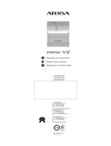
3.1 On/Off/Charger Only Switch
ON
OFF
Charger only
When switched to "on", the product is fully functional. The inverter will come into operation and the LED "inverter on" will light up.
An AC voltage connected to the "AC in" terminal will be switched through to the "AC out" terminal, if within specifications. The inverter
will switch off, the "mains on" LED will light up and the charger commences charging. The "bulk", "absorption" or "float" LEDs will light
up, depending on the charger mode.
If the voltage at the "AC-in" terminal is rejected, the inverter will switch on.
When the switch is switched to "charger only", only the battery charger of the Multi will operate (if mains voltage is present). In this mode
input voltage also is switched through to the "AC out" terminal.
NOTE: When only the charger function is required, ensure that the switch is switched to "charger only". This prevents the inverter from
being switched on if the mains voltage is lost, thus preventing your batteries from running flat.
3.2 Remote control
Remote control is possible with a 3-way switch or with a Multi Control panel.
The Multi Control panel has a simple rotary knob with which the maximum current of the AC input can be set: see PowerControl and
PowerAssist in Section 2.
3.3 Equalisation and forced absorption
3.3.1 Equalisation
Traction batteries require regular additional charging. In the equalisation mode, the MultiPlus will charge with increased voltage for one
hour (1V above the absorption voltage for a 12V battery, 2V for a 24V battery). The charging current is then limited to 1/4 of the set
value. The “bulk” and “absorption” LEDs flash intermittently.
Equalisation mode supplies a higher charging voltage than most DC consuming
devices can cope with. These devices must be disconnected before additional
charging takes place.
3.3.2 Forced absorption
Under certain circumstances, it can be desirable to charge the battery for a fixed time at absorption voltage level. In Forced Absorption
mode, the MultiPlus will charge at the normal absorption voltage level during the set maximum absorption time. The “absorption” LED
lights.
3.3.3 Activating equalisation or forced absorption
The MultiPlus can be put into both these states from the remote panel as well as with the front panel switch, provided that all switches
(front, remote and panel) are set to “on” and no switches are set to “charger only”.
In order to put the MultiPlus in this state, the procedure below should be followed.
If the switch is not in the required position after following this procedure, it can be switched over quickly once. This will not change the
charging state.
NOTE: Switching from “on” to “charger only” and back, as described below, must be done quickly. The switch must be toggled such that
the intermediate position is 'skipped', as it were. If the switch remains in the “off” position even for a short time, the device may be turned
off. In that case, the procedure must be restarted at step 1. A certain degree of familiarisation is required when using the front switch on
the Compact in particular. When using the remote panel, this is less critical.
Procedure:
1.
Check whether all switches (i.e. front switch, remote switch or remote panel switch if present) are in the “on” position.
2. Activating equalisation or forced absorption is only meaningful if the normal charging cycle is completed (charger is in 'Float').
3. To activate:
a. Switch rapidly from “on” to “charger only” and leave the switch in this position for ½ to 2 seconds.
b. Switch rapidly back from “charger only” to “on” and leave the switch in this position for ½ to 2 seconds.
c. Switch once more rapidly from “on” to “charger only” and leave the switch in this position.
4. On the MultiPlus (and, if connected, on the MultiControl panel) the three LEDs “Bulk”, “Absorption” and “Float” will now flash 5 times.
5. Subsequently, the LEDs “Bulk”, “Absorption” and “Float” will each light during 2 seconds.
a. If the switch is set to “on” while the “Bulk” LED lights, the charger will switch to equalisation.
b. If the switch is set to “on” while the “Absorption” LED lights, the charger will switch to forced absorption.
c. If the switch is set to “on” after the three LED sequence has finished, the charger will switch to “Float”.
d. If the switch has not been moved, the MultiPlus will remain in ‘charger only’ mode and switch to “Float”.

5
EN ES Appendix
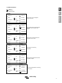
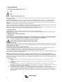
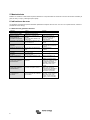
3.4 LED Indications
LED off
LED flashes
LED illuminated
Inverter
Charger
Inverter
The inverter is on and supplies
power to the load.
mains on
on
inverter on
Bulk
overload
off
Absorption
low battery
charger
only
Float
temperature
Charger
Inverter
The nominal output of the inverter is
exceeded. The “overload” LED
flashes
mains on
on
inverter on
Bulk
overload
off
absorption
low battery
charger
only
Float
temperature
Charger
Inverter
The inverter is switched off due to
overload or short circuit.
mains on
on
inverter on
Bulk
overload
off
absorption
low battery
charger
only
Float
temperature
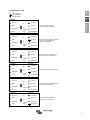
Charger
Inverter
The battery is almost fully
exhausted.
mains on
on
inverter on
Bulk
overload
off
absorption
low battery
charger
only
Float
temperature
Charger
Inverter
The inverter has switched off due to
low battery voltage.
mains on
on
inverter on
Bulk
overload
off
absorption
low battery
charger
only
Float
temperature
Charger
Inverter
The internal temperature is reaching
a critical level.
mains on
on
inverter on
Bulk
overload
off
absorption
low battery
charger
only
Float
temperature

6
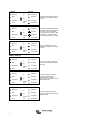
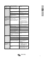
Charger
Inverter
The inverter has switched off due to
the electronics temperature being
too high.
mains on
on
inverter on
Bulk
overload
off
absorption
low battery
charger
only
Float
temperature
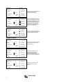
Charger
Inverter
-If the LEDs are flashing alternately,
the battery is nearly exhausted and
the nominal output is exceeded.
-If "overload" and "low battery" flash
simultaneously, the ripple voltage
on the battery terminals is too high.
mains on
on
inverter on
Bulk
overload
off
absorption
low battery
charger
only
Float
temperature
Charger
Inverter
The inverter switched off due to
excess ripple voltage on the battery
terminals.
mains on
on
inverter on
Bulk
overload
off
absorption
low battery
charger
only
Float
temperature
Battery Charger
Charger
Inverter
The AC input voltage is switched
through and the charger operates in
bulk mode.
mains on
on
inverter on
Bulk
overload
off
absorption
low battery
charger
only
Float
temperature
Charger
Inverter
The mains voltage is switched
through and the charger is on.
The set absorption voltage,
however, has not yet been reached.
(BatterySafe mode)
mains on
on
inverter on
Bulk
overload
off
absorption
low battery
charger
only
Float
temperature
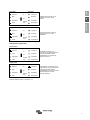
Charger
Inverter
The mains voltage is switched
through and the charger operates in
absorption mode.
mains on
on
inverter on
Bulk
overload
off
absorption
low battery
charger
only
Float
temperature

7
EN ES Appendix
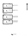
Charger
Inverter
The mains voltage is switched
through and the charger operates in
float mode.
mains on
on
inverter on
Bulk
overload
off
absorption
low battery
charger
only
Float
temperature
Charger
Inverter
The mains voltage is switched
through and the charger operates in
equalize mode.
mains on
on
inverter on
Bulk
overload
off
absorption
low battery
charger
only
Float
temperature
Special Indications
PowerControl
charger
Inverter
The AC input is switched through.
The AC output current is equal to
the preset maximum input current.
The charge current is reduced to 0.
mains on
on
inverter on
bulk
overload
off
absorption
low battery
charger
only
float
temperature
Power Assist
charger
Inverter
The AC input is switched through
but the load requires more current
than the preset maximum input
current. The inverter is switched on
to supply the required additional
current.
mains on
on
inverter on
bulk
overload
off
absorption
low battery
charger
only
float
temperature
For more error codes see section 7.3

8
5. Maintenance
The MultiPlus does not require specific maintenance. It will suffice to check all connections once a year. Avoid moisture and
oil/soot/vapours, and keep the device clean.
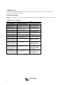
6. Error indications
With the procedures below, most errors can be quickly identified. If an error cannot be resolved, please refer to your Victron Energy
supplier.
6.1 General error indications
Problem
Cause
Solution
No output voltage on
AC-out-2.
MultiPlus in inverter mode
Multi will not switch over to
generator or mains
operation.
Circuit breaker or fuse in the
AC-in input is open as a result of
overload.
Remove overload or short
circuit on AC-out-1 or AC-out-
2, and reset fuse/breaker.
Inverter operation not
initiated when switched on.
The battery voltage is
excessively high or too low. No
voltage on DC connection.
Ensure that the battery voltage
is within the correct range.
“Low battery” LED flashes.
The battery voltage is low.
Charge the battery or check
the battery connections.
“Low battery” LED lights.
The converter switches off
because the battery voltage is
too low.
Charge the battery or check
the battery connections.
“Overload” LED flashes.
The converter load is higher than
the nominal load.
Reduce the load.
“Overload” LED lights.
The converter is switched off due
to excessively high load.
Reduce the load.
“Temperature” LED flashes
or lights.
The environmental temperature
is high, or the load is too high.
Install the converter in cool
and well-ventilated
environment, or reduce the
load.
“Low battery” and “overload”
LEDs flash intermittently.
Low battery voltage and
excessively high load.
Charge the batteries,
disconnect or reduce the load,
or install higher capacity
batteries. Fit shorter and/or
thicker battery cables.
“Low battery” and “overload”
LEDs flash simultaneously.
Ripple voltage on the DC
connection exceeds 1,5Vrms.
Check the battery cables and
battery connections. Check
whether battery capacity is
sufficiently high, and increase
this if necessary.
“Low battery” and
“overload” LEDs light.
The inverter is switched off due
to an excessively high ripple
voltage on the input.
Install batteries with a larger
capacity. Fit shorter and/or
thicker battery cables, and
reset the inverter (switch off,
and then on again).

9
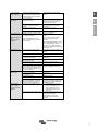
EN ES Appendix
One alarm LED
lights and the
second flashes.
The inverter is switched off due to
alarm activation by the lighted LED.
The flashing LED indicates that the
inverter was about to switch off due
to the related alarm.
Check this table for appropriate
measures in regard to this alarm
state.
The charger does
not operate.
The AC input voltage or frequency is
not within the range set.
Ensure that the AC input is between
95 VAC and 140 VAC, and that the
frequency is within the range set
(default setting 45-65Hz).
Circuit breaker or fuse in the
AC-in input is open as a result of
overload.
Remove overload or short circuit on
AC-out-1 or AC-out-2, and reset
fuse/breaker.
The battery fuse has blown.
Replace the battery fuse.
The distortion or the AC input voltage is
too large (generally generator supply).
Turn the settings WeakAC and
dynamic current limiter on.
The charger does
not operate.
“Bulk” LED flashes
and
“Mains on” LED
illuminates.
MultiPlus is in “Bulk protection” mode
thus, the maximum bulk charging time
of 10 hours is exceeded.
Such a long charging time could
indicate a system error (e.g. a battery
cell short-circuit).
Check your batteries.
NOTE:
You can reset the error mode by
switching off and back on the
MultiPlus.
The standard MultiPlus factory setting
of the “Bulk protection” mode is
switched on. The “Bulk protection”
mode can be switched off with help of
VEConfigure only.
The battery is not
completely charged.
Charging current excessively high,
causing premature absorption phase.
Set the charging current to a level
between 0.1 and 0.2 times the battery
capacity.
Poor battery connection.
Check the battery connections.
The absorption voltage has been set to
an incorrect level (too low).
Set the absorption voltage to the
correct level.
The float voltage has been set to an
incorrect level (too low).
Set the float voltage to the correct
level.
The available charging time is too short
to fully charge the battery.
Select a longer charging time or
higher charging current.
The absorption time is too short. For
adaptive charging this can be caused
by an extremely high charging current
with respect to battery capacity, so that
bulk time is insufficient.
Reduce the charging current or select
the ‘fixed’ charging characteristics.
The battery is
overcharged.
The absorption voltage is set to an
incorrect level (too high).
Set the absorption voltage to the
correct level.
The float voltage is set to an incorrect
level (too high).
Set the float voltage to the correct
level.
Poor battery condition.
Replace the battery.
The battery temperature is too high
(due to poor ventilation, excessively
high environmental temperature, or
excessively high charging current).
Improve ventilation, install batteries
in a cooler environment, reduce the
charging current, and connect the
temperature sensor.
The charging
current drops to 0
as soon as the
absorption phase
initiates.
The battery is over-heated (>50°C)
─ Install the battery in a cooler
environment
─ Reduce the charging current
─ Check whether one of the
battery cells has an internal
short circuit
Defective battery temperature sensor
Disconnect the temperature sensor
plug in the MultiPlus. If charging
functions correctly after
approximately 1 minute, the
temperature sensor should be
replaced.

10
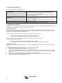
6.2 Special LED indications
(for the normal LED indications, see section 3.4)
Bulk and absorption LEDs flash synchronously
(simultaneously).
Voltage sense error. The voltage measured at the voltage sense connection
deviates too much (more than 7V) from the voltage on the positive and
negative connection of the device. There is probably a connection error.
The device will remain in normal operation.
NOTE: If the "inverter on" LED flashes in phase opposition, this is a VE.Bus
error code (see further on).
Absorption and float LEDs flash synchronously
(simultaneously).
The battery temperature as measured has an extremely unlikely value. The
sensor is probably defective or has been incorrectly connected. The device
will remain in normal operation.
NOTE: If the "inverter on" LED flashes in phase opposition, this a VE.Bus
error code (see further on).
"Mains on" flashes and there is no output voltage.
The device is in "charger only" operation and mains supply is present. The
device rejects the mains supply or is still synchronising.
6.3 VE.Bus LED indications
Equipment included in a VE.Bus system (a parallel or 3-phase arrangement) can provide so-called VE.Bus LED indications. These LED
indications can be subdivided into two groups: OK codes and error codes.
6.3.1 VE.Bus OK codes
If the internal status of a device is in order but the device cannot yet be started because one or more other devices in the system
indicate an error status, the devices that are in order will indicate an OK code. This facilitates error tracing in a VE.Bus system, since
devices not requiring attention are easily identified as such.
Important: OK codes will only be displayed if a device is not in inverter or charging operation!
• A flashing "bulk" LED indicates that the device can perform inverter operation.
• A flashing "float" LED indicates that the device can perform charging operation.
NOTE: In principle, all other LEDs must be off. If this is not the case, the code is not an OK code.
However, the following exceptions apply:
• The special LED indications above can occur together with the OK codes.
• The "low battery" LED can function together with the OK code that indicates that the device can charge.
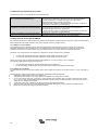
6.3.2 VE.Bus error codes
A VE.Bus system can display various error codes. These codes are displayed with the "inverter on", "bulk", "absorption" and "float"
LEDs.
To interpret a VE.Bus error code correctly, the following procedure should be followed:
1. The device should be in error (no AC output).
2. Is the "inverter on" LED flashing? If not, then there is no VE.Bus error code.
3. If one or more of the LEDs "bulk", "absorption" or "float" flashes, then this flash must be in phase opposition to the "inverter on"
LED, i.e. the flashing LEDs are off if the "inverter on" LED is on, and vice versa. If this is not the case, then there is no VE.Bus
error code.
4. Check the "bulk" LED, and determine which of the three tables below should be used.
5. Select the correct column and row (depending on the "absorption" and "float" LEDs), and determine the error code.
6. Determine the meaning of the code in the tables below.

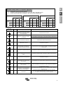
11
EN ES Appendix
All of the conditions below must be met!:
1. The device is in error! (No AC output)
2. Inverter LED flashes (in opposition to any flashing of the Bulk, Absorption or Float LED)
3. At least one of the LEDs Bulk, Absorption and Float is on or flashing
Bulk LED off Bulk LED flashes Bulk LED on
Absorption LED Absorption LED Absorption LED
off
flashing
On
off
flashing
on
off
flashing
on
Float LED
off 0 3 6
Float LED
off 9 12 15
Float LED
off 18 21 24
flashing 1 4 7 flashing 10 13 16 flashing 19 22 25
on 2 5 8 on 11 14 17 on 20 23 26
Bulk LED
Absorption LED
Float LED
Code Meaning: Cause/solution:
1
Device is switched off because one of
the other phases in the system has
switched off.
Check the failing phase.
3
Not all, or more than, the expected
devices were found in the system.
The system is not properly configured. Reconfigure the system.
Communication cable error. Check the cables and switch all equipment off,
and then on again.
4 No other device whatsoever detected. Check the communication cables.
5 Overvoltage on AC-out. Check the AC cables.
10
System time synchronisation problem
occurred.
Should not occur in correctly installed equipment. Check the communication
cables.
14 Device cannot transmit data. Check the communication cables (there may be a short circuit).
17
One of the devices has assumed
‘master’ status because the original
master failed.
Check the failing unit. Check the communication cables.
18 Overvoltage has occurred. Check AC cables.
22 This device cannot function as ‘slave’. This device is an obsolete and unsuitable model. It should be replaced.
24 Switch-over system protection initiated.
Should not occur in correctly installed equipment. Switch all equipment off,
and then on again. If the problem recurs, check the installation.
25
Firmware incompatibility. The firmware
of one the connected devices is not
sufficiently up to date to operate in
conjunction with this device.
1) Switch all equipment off.
2) Switch the device returning this error message on.
3) Switch on all other devices one by one until the error message reoccurs.
4) Update the firmware in the last device that was switched on.
26 Internal error.
Should not occur. Switch all equipment off, and then on again. Contact
Victron Energy if the problem persists.

12
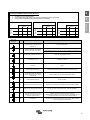
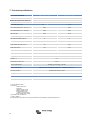
7. Technical specifications
MultiPlus
12/3000/120-50 120V
24/3000/70-50 120V
PowerControl / PowerAssist
Yes
AC input
Input voltage range: 95-140VAC; Input frequency: 45 – 65Hz; Power factor: 1
Maximum feed through current
50
Minimum AC supply current capacity for
PowerAssist (A)
7,5
INVERTER
Input voltage range (V DC)
9,5 – 17
19 – 33
Output (1)
Output voltage: 120 VAC ± 2% Frequency: 60 Hz ± 0,1%
Cont. output power at 25°C / 77°F (VA) (3)
3000
3000
Cont. output power at 25°C / 77°F (W)
2400
2400
Cont. output power at 40°C / 104°F (W)
2200
2200
Cont. output power at 65°C / 150°F (W)
1700
1700
Peak power (W)
6000
6000
Maximum efficiency (%)
93
94
Zero-load power (W) 20 20
Zero-load power in AES mode (W) 15 15
Zero-load power in Search mode (W)
8
10
CHARGER
AC Input
Input voltage range: 95-140VAC Input frequency: 45 – 65Hz Power factor: 1
Charge voltage 'absorption' (V DC)
14,4
28,8
Charge voltage 'float' (V DC)
13,8
27,6
Storage mode (V DC)
13,2
26,4
Charge current house battery (A) (4)
120
70
Charge current starter battery (A)
4
Battery temperature sensor
Yes
GENERAL
Auxiliary output
Max. 32A Switches off when no external AC source available
Programmable relay
(5)
Yes, 3x
Protection (2)
a - g
VE.Bus communication port
For parallel and three phase operation, remote monitoring and system integration
General purpose comm. port
Yes, 2x
Common Characteristics
Operating temp.: -40 to +65°C/ -40 - 150°F (fan assisted cooling)
Humidity (non-condensing) : max 95%
ENCLOSURE
Common Characteristics
Material & Colour: aluminium (blue RAL 5012) Protection category: IP 21
Battery-connection
M8 bolts (2 plus and 2 minus connections)
120V AC-connections
Screw terminals 13mm² (6 AWG)
Weight (kg)
19
Dimensions (hxwxd in mm)
362 x 258 x 218
STANDARDS
Safety
UL1741, UL458, EN 60335-1, EN 60335-2-29
Emission / Immunity
EN 55014-1, EN 55014-2, EN 61000-3-3
Automotive Directive
2004/104/EC
1) Can be adjusted to 50Hz;
2) Protection
a. Output short circuit
b. Overload
c. Battery voltage too high
d. Battery voltage too low
e. Temperature too high
f. 120VAC on inverter output
g. Input voltage ripple too high
3) Non linear load, crest factor 3:1
4) At 25°C ambient
5) Programmable relay which can be set for general alarm, DC undervoltage or genset start/stop function

1
EN ES Appendix
1. INSTRUCCIONES DE SEGURIDAD
En general
Lea en primer lugar la documentación que acompaña al producto para familiarizarse con las indicaciones de seguridad y las
instrucciones antes de utilizarlo.
Este producto se ha diseñado y comprobado de acuerdo con los estándares internacionales. El equipo debe utilizarse exclusivamente
para la aplicación prevista.
ADVERTENCIA: PELIGRO DE DESCARGA ELÉCTRICA
El producto se usa junto con una fuente de alimentación permanente (batería). Aunque el equipo esté apagado, puede producirse una
tensión eléctrica peligrosa en los terminales de entrada y salida. Apague siempre la alimentación CA y desconecte la batería antes de
realizar tareas de mantenimiento.
El producto no contiene piezas en su interior que puedan ser manipuladas por el usuario. No retire el panel frontal ni ponga el producto
en funcionamiento si no están colocados todos los paneles. Las operaciones de mantenimiento deben ser realizadas por personal
cualificado.
No utilice nunca el equipo en lugares donde puedan producirse explosiones de gas o polvo. Consulte las especificaciones
suministradas por el fabricante de la batería para asegurarse de que puede utilizarse con este producto. Las instrucciones de seguridad
del fabricante de la batería deben tenerse siempre en cuenta.
AVISO: no levante objetos pesados sin ayuda.
Instalación
Lea las instrucciones antes de comenzar la instalación.
Este producto es un dispositivo de clase de seguridad I (suministrado con terminal de puesta a tierra para seguridad). Sus terminales
de salida CA deben estar puestos a tierra continuamente por motivos de seguridad. Hay otro punto de puesta a tierra
adicional en la parte exterior del producto. Si se sospecha que la puesta a tierra está dañada, el equipo debe desconectarse y evitar
que se pueda volver a poner en marcha de forma accidental; póngase en contacto con personal técnico cualificado.
Compruebe que los cables de conexión disponen de fusibles y disyuntores. No sustituya nunca un dispositivo de protección por un
componente de otro tipo. Consulte en el manual las piezas correctas.
Antes de encender el dispositivo compruebe si la fuente de alimentación cumple los requisitos de configuración del producto descritos
en el manual.
Compruebe que el equipo se utiliza en las condiciones adecuadas de funcionamiento. No lo utilice en un ambiente húmedo o con
polvo.
Compruebe que hay suficiente espacio alrededor del producto para su ventilación y que los orificios de ventilación no están tapados.
Instale el producto en un entorno a prueba del calor. Compruebe que no haya productos químicos, piezas de plástico, cortinas u otros
textiles, etc., en las inmediaciones del equipo.
Transporte y almacenamiento
Para transportar o almacenar el producto, asegúrese de que los cables de alimentación principal y de la batería estén desconectados.
No se aceptará ninguna responsabilidad por los daños producidos durante el transporte si el equipo no lleva su embalaje original.
Guarde el producto en un entorno seco, la temperatura de almacenamiento debe oscilar entre –20°C y 60°C.
Consulte el manual del fabricante de la batería para obtener información sobre el transporte, almacenamiento, recarga y eliminación de
la batería.

2
2. DESCRIPCIÓN
2.1 En general
La base de MultiPlus es un inversor sinusoidal extremadamente potente, cargador de batería y conmutador automático en una carcasa
compacta.
MultiPlus presenta las siguientes características adicionales, muchas de ellas exclusivas:
Conmutación automática e ininterrumpida
En caso de fallo de la alimentación o cuando se apaga el grupo generador, MultiPlus cambiará a funcionamiento de inversor y se
encargará del suministro de los dispositivos conectados. Esta operación es tan rápida que el funcionamiento de ordenadores y otros
dispositivos eléctricos no se ve interrumpido (Sistema de alimentación ininterrumpida o SAI). MultiPlus resulta pues muy adecuado
como sistema de alimentación de emergencia en aplicaciones industriales y de telecomunicaciones. La corriente alterna máxima que
se puede conmutar es 16A o 50 A, según el modelo.
Salida CA auxiliar
Además de la salida ininterrumpida, hay una salida auxiliar disponible que desconecta su carga en caso de funcionamiento con batería.
Ejemplo: hay una caldera eléctrica que sólo funciona con el grupo generador en marcha o con corriente de pantalán.
Potencia prácticamente ilimitada gracias al funcionamiento en paralelo
Hasta 6 Mults pueden funcionar en paralelo. Seis unidades 24/3000/70, por ejemplo, darán una potencia de salida de 15 kW/18 kVA y
una capacidad de carga de 420 amperios.
Capacidad de funcionamiento trifásico
Se pueden configurar tres unidades para salida trifásica. Pero eso no es todo: hasta 6 grupos de tres unidades pueden conectarse en
paralelo para lograr una potencia del inversor de 45kW/54 kVA y más de 1.000 A de capacidad de carga.
PowerControl – máximo uso de la corriente de red cuando es limitada
MultiPlus puede generar una enorme corriente de carga. Esto supone una sobrecarga de la conexión del pantalán o del grupo
generador. Por lo tanto, se puede establecer una corriente máxima. MultiPlus tiene en cuenta otros usuarios de corriente y sólo usa la
corriente "excedente" para cargar.
PowerAssist – Uso ampliado de su generador y de la corriente de red: función MultiPlus “cosuministro”
Esta función lleva el principio de PowerControl a otra dimensión, permitiendo que el MultiPlus complemente la capacidad de la fuente
alternativa. Cuando se requiera un pico de potencia durante un corto espacio de tiempo, como pasa a menudo, el MultiPlus
compensará inmediatamente la posible falta de potencia de la corriente de la red o del generador con potencia de la batería. Cuando
se reduce la carga, la potencia sobrante se utiliza para recargar la batería.
Esta función única ofrece la solución definitiva para el "problema de corriente de red": herramientas eléctricas de alta
potencia, lavavajillas, lavadoras, cocinas eléctricas, etc., pueden funcionar con la corriente de red de 16 A, e incluso menos.
Además, se puede instalar un pequeño generador.
Tres relés programables
Estos relé puede programarse para cualquier tipo de aplicación, por ejemplo como relé de arranque para un grupo generador.
Dos puertos programables analógicos/digitales de entrada/salida
Estos puertos pueden usarse para distintos fines. Una aplicación sería la de comunicarse con el BMS o con una batería de iones de
litio.
Cambio de frecuencia
Cuando los inversores solares están conectados a la salida de un Multi o de un Quattro, el excedente de energía solar se utiliza para
recargar las baterías. Una vez alcanzada la tensión de absorción, el Multi o Quattro detendrán el inversor solar cambiando la frecuencia
de salida en 1Hz (de 50Hz a 51Hz, por ejemplo). Cuando la tensión de la batería haya caído ligeramente, la frecuencia volverá a su
valor normal y los inversores solares volverán a funcionar.
Monitor de baterías integrado (opcional)
La solución ideal cuando Multis o Quattros forman parte de un sistema híbrido (generador diesel, inversor/cargadores, batería
acumuladora y energía alternativa). El monitor de baterías integrado puede configurarse para arrancar y detener el generador.
- Arrancar cuando se alcance un % de descarga predeterminado, y/o
- arrancar (con una demora preestablecida) cuando se alcance una tensión de la batería predeterminada, y/o
- arrancar (con una demora preestablecida) cuando se alcance un nivel de carga predeterminado.
- Detener cuando se alcance una tensión de la batería predeterminada, o
- detener (con un tiempo de demora preestablecido) una vez completada la fase de carga "bulk", y/o
- detener (con una demora preestablecida) cuando se alcance un nivel de carga predeterminado.
Energía solar
MultiPlus es perfecto para las aplicaciones de energía solar. Puede utilizarse en sistemas autónomos, así como en sistemas
conectados a la red.

3
EN ES Appendix
Funcionamiento autónomo en caso de apagón
Las casas o edificios provistos de paneles solares o una micro central eléctrica u otras fuentes de energía sostenible tienen un
suministro de energía autónoma potencial que puede utilizarse para alimentar equipos esenciales (bombas de calefacción central,
refrigeradores, congeladores, conexiones de Internet, etc.) cuando hay fallos de alimentación. Sin embargo, el problema es que las
fuentes de energía sostenible conectadas a la red se caen nada más fallar la red. Con MultiPlus y baterías, este problema puede
resolverse de una manera sencilla: MultiPlus puede sustituir a la red cuando se produce un apagón. Cuando las fuentes de
energía sostenible producen más potencia de la necesaria, MultiPlus utilizará el excedente para cargar las baterías; en caso de
potencia insuficiente, MultiPlus suministrará alimentación adicional de la batería.
Programable con conmutadores DIP, panel VE.Net u ordenador personal
El MultiPlus se suministra listo para usar. Hay tres funciones para cambiar determinados ajustes si se desea:
─ Los ajustes más importantes (incluyendo el funcionamiento en paralelo de hasta tres dispositivos y el funcionamiento trifásico) se
puede cambiar muy fácilmente con los conmutadores DIP.
─ Todos los valores, con la excepción del relé multifuncional, pueden cambiarse con un panel VE.Net.
─ Todos los valores se pueden cambiar con un PC y el software gratuito que se puede descargar desde nuestro sitio web
www.victronenergy.com
2.2 Cargador de batería
Carga variable de 4 etapas: inicial – absorción – flotación - almacenamiento
El sistema de gestión de baterías variable activado por microprocesador puede ajustarse a distintos tipos de baterías. La función
variable adapta automáticamente el proceso de carga al uso de la batería.
La cantidad de carga correcta: tiempo de absorción variable
En caso de una ligera descarga de la batería, la absorción se reduce para evitar sobrecargas y una formación excesiva de gases.
Después de una descarga profunda, el tiempo de absorción se amplía automáticamente para cargar la batería completamente.
Prevención de daños por un exceso de gaseado: el modo BatterySafe
Si, para cargar una batería rápidamente, se ha elegido una combinación de alta corriente de carga con una tensión de absorción alta,
se evitará que se produzcan daños por exceso de gaseado limitando automáticamente el ritmo de incremento de tensión una vez se
haya alcanzado la tensión de gaseado.
Menor envejecimiento y necesidad de mantenimiento cuando la batería no está en uso: el modo de almacenamiento
El modo de almacenamiento se activa cuando la batería no ha sufrido ninguna descarga en 24 horas. En el modo de almacenamiento,
la tensión de flotación se reduce a 2,2V/celda (13,2V para baterías de 12V) para reducir el gaseado y la corrosión de las placas
positivas. Una vez a la semana, se vuelve a subir la tensión a nivel de absorción para “igualar” la batería. Esta función evita la
estratificación del electrolito y la sulfatación, las causas principales de los fallos en las baterías.
Dos salidas CC para cargar dos baterías
El terminal CC principal puede suministrar la totalidad de la corriente de salida. La segunda salida, pensada para cargar una batería de
arranque, se limita a 4 A y tiene una tensión de salida ligeramente menor.
Incremento de la vida útil de la batería: compensación de temperatura
El sensor de temperatura (suministrado con el producto) sirve para reducir la tensión de carga cuando la temperatura de la batería
sube. Esto es muy importante para las baterías sin mantenimiento que de otro modo se secarían por sobrecarga.
Sonda de tensión de la batería: la tensión de carga adecuada
La pérdida de tensión debido a la resistencia del cable puede compensarse utilizando la sonda de tensión para medir la misma
directamente en el bus CC o en los terminales de la batería.
Más información sobre baterías y cargas
Nuestro libro "Energy Unlimited" ofrece más información sobre baterías y carga de baterías y puede conseguirse gratuitamente en
nuestro sitio web (www.victronenergy.com Asistencia y descargas Información técnica general). Para más información sobre
carga variable, le rogamos consulte el apartado Información técnica general de nuestro sitio web.

4
3. FUNCIONAMIENTO
3.1 Conmutador On/Off/Charger only
ON
OFF
Charger only (Cargador sólo)
Al poner el conmutador en “on”, el producto es plenamente operativo. El inversor se pone en marcha y el LED “inverter on” (inversor
activado) se enciende.
Una tensión CA conectada al terminal “AC-in” (CA de entrada) se conmutará a través del terminal “AC-out”, (CA de salida) si está
dentro de las especificaciones. El inversor se apagará, el LED “mains on” (red activada) se encenderá y el cargador empezará a
cargar. Los LED “bulk” (inicial), “absorption” (absorción) o “float” (carga lenta) se encenderán, según el modo en que se encuentre el
cargador.
Si la tensión en el terminal “AC-in” se rechaza, el inversor se encenderá.
Cuando el conmutador se pone en “charger only” (cargador sólo), sólo funcionará el cargador de batería del Multi (si hay tensión de la
red). En este modo, la tensión de entrada también se conmuta al terminal de salida "AC-out".
NOTA: Cuando sólo necesite la función de carga, asegúrese de que el conmutador está en “charger only”. Esto hará que no se active
el inversor si se pierde la tensión de la red, evitando así que sus baterías se queden sin carga.
3.2 Control remoto
Es posible utilizar un control remoto con un interruptor de tres vías o con UN panel Multi Control.
El panel de Multi Control tiene un selector giratorio con el que se puede fijar la corriente máxima de entrada CA: ver PowerControl y
PowerAssist en la Sección 2.
3.3 Ecualización y absorción forzada
3.3.1 Ecualización
Las baterías de tracción necesitan cargarse de forma regular. En modo ecualización, MultiPlus cargará con mayor tensión durante una
hora (1 V sobre la tensión de absorción para una batería de 12 V, 2 V para una de 24 V). La corriente de carga se limita después a ¼
del valor establecido. Los LED “bulk” (inicial) y “absorption” (absorción) parpadean alternativamente.
El modo de ecualización suministra una tensión de carga superior de la que
pueden soportar la mayoría de los dispositivos que consumen CC. Estos
dispositivos deben desconectarse antes de proceder a la carga adicional.
3.3.2 Absorción forzada
En determinadas circunstancias puede ser mejor cargar la batería durante un tiempo fijo al nivel de tensión de absorción. En el modo
de absorción forzada, el MultiPlus cargará al nivel normal de tensión de absorción durante el máximo tiempo de absorción establecido.
El LED "absorción" se ilumina.
3.3.3 Activación de la ecualización o absorción forzada
MultiPlus puede ponerse en ambos estados tanto desde el panel remoto como desde el conmutador del panel frontal, siempre que
todos los conmutadores (frontal, remoto y panel) estén "activados" y ninguno de ellos esté en "cargador sólo".
Para poner el MultiPlus en este estado, hay que seguir el procedimiento que se indica a continuación.
Si el conmutador no está en la posición deseada después de hacer este procedimiento, puede volver a cambiarse rápidamente una vez.
De esta forma no se cambiará el estado de carga-
NOTA: El cambio de "activado” a “cargador sólo” y viceversa, como se describe a continuación, debe hacerse rápidamente. El
conmutador debe girarse de forma que la posición intermedia se "salte", por así decirlo. Si el conmutador permaneciera en la posición
"off" aunque sólo sea un momento, el dispositivo podría apagarse. En este caso, deberá reiniciarse el procedimiento a partir del paso 1.
Se necesita un cierto grado de familiarización al usar el conmutador frontal del Compact en particular. Cuando se usa el panel remoto,
esto no es tan importante.
Procedimiento:
6.
Compruebe que todos los conmutadores (es decir, conmutador frontal, remoto o el panel remoto en su caso) están en la posición “on”
(activado).
7. La activación de la ecualización o de la absorción forzada sólo tiene sentido si se ha completado el ciclo de carga normal (el cargador está en
"Float" (flotación)).
8. Para activarla:
a. Cambiar rápidamente de “on” a “charger only” y dejar el interruptor en esta posición durante ½ ó 2 segundos.b. Volver a cambiar
rápidamente de “charger only” a “on” y dejar el interruptor en esta posición durante ½ ó 2 segundos.c. Cambiar rápidamente una vez más de
“on” a “charger only” y dejar el interruptor en esta posición.
9. En el MultiPlus (y, si estuviera conectado, en el panel MultiControl) parpadearán 5 veces los LED “Bulk”, “Absorption” y “Float”.
10. A continuación, los LED “Bulk”, “Absorption” y “Float” se encenderán cada uno durante 2 segundos.a. Si el interruptor está en “on” mientras
se enciende el LED “Bulk”, el cargador conmutará a modo ecualización.b. Si el interruptor está en “on” mientras se enciende el LED
“Absorption”, el cargador conmutará a modo de absorción forzada.c. Si el interruptor está en “on” después de que las tres secuencias de los
LED haya terminado, el cargador conmutará a “Float”.d. Si el interruptor no se ha movido, el MultiGrid se quedará en modo “charger only” y
conmutará a “Float”.

5
EN ES Appendix
3.4 Indicadores LED
LED apagado
LED intermitente
LED encendido
Inversor
Cargador
Inversor
El inversor está encendido y
suministra energía a la carga.
mains on
on
inverter on
Bulk
overload
off
Absorption
low battery
charger
only
Float
temperature
Cargador
Inversor
Se ha excedido la salida nominal del
inversor. El LED indicador de
“sobrecarga" parpadea.
mains on
on
inverter on
Bulk
overload
off
absorption
low battery
charger
only
Float
temperature
Cargador
Inversor
El inversor se ha parado debido a
una sobrecarga o cortocircuito.
mains on
on
inverter on
Bulk
overload
off
absorption
low battery
charger
only
Float
temperature
Cargador
Inversor
La batería está prácticamente vacía.
mains on
on
inverter on
Bulk
overload
off
absorption
low battery
charger
only
Float
temperature
Cargador
Inversor
El inversor se ha parado debido a la
baja tensión de la batería.
mains on
on
inverter on
Bulk
overload
off
absorption
low battery
charger
only
Float
temperature
Cargador
Inversor
La temperatura interna está
alcanzando un nivel crítico.
mains on
on
inverter on
Bulk
overload
off
absorption
low battery
charger
only
Float
temperature

6
Cargador
Inversor
El inversor se ha parado debido a la
temperatura excesiva de los
componentes electrónicos.
mains on
on
inverter on
Bulk
overload
off
absorption
low battery
charger
only
Float
temperature
Cargador
Inversor
-Si los LED parpadean de manera
alterna, la batería está casi vacía y
se ha superado la potencia nominal.
-Si "overload" (sobrecarga) y "low
battery" (batería baja) parpadean
simultáneamente, la tensión de
ondulación en los terminales de la
batería es demasiado alta.
mains on
on
inverter on
Bulk
overload
off
absorption
low battery
charger
only
Float
temperature
Cargador
Inversor
El inversor se ha parado debido a
un exceso de tensión de ondulación
en los terminales de la batería.
mains on
on
inverter on
Bulk
overload
off
absorption
low battery
charger
only
Float
temperature
Cargador de batería
Cargador
Inversor
La tensión CA de entrada se activa
y el cargador funciona en modo
inicial o absorción.
mains on
on
inverter on
Bulk
overload
off
absorption
low battery
charger
only
Float
temperature
Cargador
Inversor
La tensión de red se activa y el
cargador se pone a funcionar.
Sin embargo, la tensión de
absorción establecida todavía no se
ha alcanzado. (Modo BatterySafe)
mains on
on
inverter on
Bulk
overload
off
absorption
low battery
charger
only
Float
temperature
Cargador
Inversor
La tensión de red se activa y el
cargador funciona en modo
absorción.
mains on
on
inverter on
Bulk
overload
off
absorption
low battery
charger
only
Float
temperature
Page is loading ...
Page is loading ...
Page is loading ...
Page is loading ...
Page is loading ...
Page is loading ...
Page is loading ...
Page is loading ...
-
 1
1
-
 2
2
-
 3
3
-
 4
4
-
 5
5
-
 6
6
-
 7
7
-
 8
8
-
 9
9
-
 10
10
-
 11
11
-
 12
12
-
 13
13
-
 14
14
-
 15
15
-
 16
16
-
 17
17
-
 18
18
-
 19
19
-
 20
20
-
 21
21
-
 22
22
-
 23
23
-
 24
24
-
 25
25
-
 26
26
-
 27
27
-
 28
28


Victron energy MultiPlus 3k 120V (firmware xxxx4xx) User manual
- Type
- User manual
- This manual is also suitable for
Ask a question and I''ll find the answer in the document
Finding information in a document is now easier with AI
in other languages
Related papers
-
Victron energy MultiPlus 3k 120V (firmware xxxx4xx) Owner's manual
-
-
-
Victron energy MultiPlus-II User manual
-
-
-
-
-
-
Victron energy MultiPlus-II 12 3000 120-32 User manual
Other documents
-
Dicota D30144 Datasheet
-
 Salicru NX Series User manual
-
Pride POWER ASSIST Owner's manual
-
 Salicru Soho series User manual
-
Vetus COMBI3012 Owner's manual
-
-
 Salicru SPS.600.SOHO User manual
-
 atersa MINO V2 Series User manual
-
-
 Uno BATTERIES 0552 Operating instructions


