Page is loading ...

cover 1/94 − ST-146 129-B PRINTED IN USA
1994 MILLER Electric Mfg. Co.
CC/DC Welding Power Source
For GTAW, GTAW-P, And SMAW Welding
300 Amperes, 32 Volts DC At 60% Duty Cycle
Uses Single-Phase Or Three-Phase Input Power
Protection For 24 VAC And Overheating
AUTO-LINK Circuitry
14-Pin Remote Control Receptacle
See Rear Cover For Options And Accessories
Read and follow these instructions and all
safety blocks carefully.
Have only trained and qualified persons
install, operate, or service this unit.
Call your distributor if you do not understand
the directions.
Give this manual to the operator.
For help, call your distributor
or: MILLER Electric Mfg. Co., P.O. Box 1079,
Appleton, WI 54912 414-734-9821
OWNER’S
MANUAL
April 1994 Form: OM-299F
Effective With Serial No. KE626910
XMT 300 CC

OM-299F − 4/94
EMF INFORMATION
The following is a quotation from the General Conclusions Section of
the U.S. Congress, Office of Technology Assessment, Biological
Effects of Power Frequency Electric & Magnetic Fields −
Background Paper, OTA-BP-E-53 (Washington, DC: U.S.
Government Printing Office, May 1989): “. . . there is now a very large
volume of scientific findings based on experiments at the cellular
level and from studies with animals and people which clearly
establish that low frequency magnetic fields can interact with, and
produce changes in, biological systems. While most of this work is
of very high quality, the results are complex. Current scientific
understanding does not yet allow us to interpret the evidence in a
single coherent framework. Even more frustrating, it does not yet
allow us to draw definite conclusions about questions of possible risk
or to offer clear science-based advice on strategies to minimize or
avoid potential risks.”
To reduce magnetic fields in the workplace, use the following
procedures:
1. Keep cables close together by twisting or taping them.
2. Arrange cables to one side and away from the operator.
3. Do not coil or drape cables around the body.
4. Keep welding power source and cables as far away as practical.
5. Connect work clamp to workpiece as close to the weld as
possible.
About Pacemakers:
The above procedures are among those also normally
recommended for pacemaker wearers. Consult your doctor for
complete information.
Considerations About Welding And The Effects Of Low Frequency Electric And
Magnetic Fields
NOTE
mod10.1 4/93
TABLE OF CONTENTS
SECTION 1 − SAFETY INFORMATION 1. . . . . . . . . . . . . . . . . . . . . . . . . . . . . . . . . . . . . . . . . . . . . . . . . . . .
SECTION 2 − SPECIFICATIONS
2-1. Volt-Ampere Curves 2. . . . . . . . . . . . . . . . . . . . . . . . . . . . . . . . . . . . . . . . . . . . . . . . . . . . . . . . . . . .
2-2. Duty Cycle 2. . . . . . . . . . . . . . . . . . . . . . . . . . . . . . . . . . . . . . . . . . . . . . . . . . . . . . . . . . . . . . . . . . . .
SECTION 3 − INSTALLATION
3-1. Typical Process Connections 3. . . . . . . . . . . . . . . . . . . . . . . . . . . . . . . . . . . . . . . . . . . . . . . . . . . .
3-2. Selecting A Location And Moving Welding Power Source 3. . . . . . . . . . . . . . . . . . . . . . . . . . . .
3-3. Selecting And Preparing Weld Output Cables 4. . . . . . . . . . . . . . . . . . . . . . . . . . . . . . . . . . . . . .
3-4. Connecting To Weld Output Receptacles 5. . . . . . . . . . . . . . . . . . . . . . . . . . . . . . . . . . . . . . . . . .
3-5. Remote 14 Receptacle Information And Connections 6. . . . . . . . . . . . . . . . . . . . . . . . . . . . . . .
3-6. Connecting Input Power 7. . . . . . . . . . . . . . . . . . . . . . . . . . . . . . . . . . . . . . . . . . . . . . . . . . . . . . . .
SECTION 4 − OPERATION 8. . . . . . . . . . . . . . . . . . . . . . . . . . . . . . . . . . . . . . . . . . . . . . . . . . . . . . . . . . . . . . .
SECTION 5 − MAINTENANCE & TROUBLESHOOTING
5-1. Routine Maintenance 12. . . . . . . . . . . . . . . . . . . . . . . . . . . . . . . . . . . . . . . . . . . . . . . . . . . . . . . . . . .
5-2. Removing Case And Measuring Input Capacitor Voltage 13. . . . . . . . . . . . . . . . . . . . . . . . . . . .
5-3. Overload Protection 14. . . . . . . . . . . . . . . . . . . . . . . . . . . . . . . . . . . . . . . . . . . . . . . . . . . . . . . . . . . .
5-4. Changing Amperage/Voltage Meter Hold Function 15. . . . . . . . . . . . . . . . . . . . . . . . . . . . . . . . . .
5-5. Troubleshooting 15. . . . . . . . . . . . . . . . . . . . . . . . . . . . . . . . . . . . . . . . . . . . . . . . . . . . . . . . . . . . . . .
SECTION 6 − ELECTRICAL DIAGRAMS 18. . . . . . . . . . . . . . . . . . . . . . . . . . . . . . . . . . . . . . . . . . . . . . . . . . .
SECTION 7 − TUNGSTEN ELECTRODE
7-1. Selecting Tungsten Electrode 22. . . . . . . . . . . . . . . . . . . . . . . . . . . . . . . . . . . . . . . . . . . . . . . . . . . .
7-2. Preparing Tungsten 23. . . . . . . . . . . . . . . . . . . . . . . . . . . . . . . . . . . . . . . . . . . . . . . . . . . . . . . . . . . .
SECTION 8 − PARTS LIST
Figure 8-1. Main Assembly 24. . . . . . . . . . . . . . . . . . . . . . . . . . . . . . . . . . . . . . . . . . . . . . . . . . . . . . . . . . . .
Figure 8-2. Panel, Front w/Components 26. . . . . . . . . . . . . . . . . . . . . . . . . . . . . . . . . . . . . . . . . . . . . . . . .
Figure 8-3. Chassis, Mid 28. . . . . . . . . . . . . . . . . . . . . . . . . . . . . . . . . . . . . . . . . . . . . . . . . . . . . . . . . . . . . .

OM-299 Page 1
SECTION 1 − SAFETY INFORMATION
mod1.1 2/93
Read all safety messages throughout this manual.
Obey all safety messages to avoid injury.
Learn the meaning of WARNING and CAUTION.
1 Safety Alert Symbol
2 Signal Word
WARNING means possible death
or serious injury can happen.
CAUTION means possible minor
injury or equipment damage can
happen.
3 Statement Of Hazard And Re-
sult
4 Safety Instructions To Avoid
Hazard
5 Hazard Symbol (If Available)
6 Safety Banner
Read safety blocks for each sym-
bol shown.
7 NOTE
Special instructions for best oper-
ation − not related to safety.
2
NOTE
ELECTRIC SHOCK can kill.
• Do not touch live electrical parts.
• Disconnect input power before
installing or servicing.
WARNING
READ SAFETY BLOCKS at start of
Section 3-1 before proceeding.
WARNING
5
4
6
7
1 2
CAUTION
MOVING PARTS can injure.
• Keep away from moving parts.
• Keep all panels and covers closed
when operating.
3
Turn Off switch when using high frequency.
Figure 1-1. Safety Information
SECTION 2 − SPECIFICATIONS
Table 2-1. Welding Power Source
Specification Description
Type Of Output Constant Current/Direct Current (CC/DC)
Welding Processes Scratch Start Gas Tungsten Arc (GTAW), Scratch Start Gas Tungsten Arc - Pulsed (GTAW-P),
Shielded Metal Arc Welding (SMAW)
Input Power Cord 12 ft (3.7 m)
Overall Dimensions Length: 21-3/4 in (522 mm); Width: 12 in (305 mm); Height: 17-3/8 in (441 mm)
Weight Net: 77 lb (35 kg); Ship: 82 lb (37 kg)
With Three-Phase Input With Single-Phase Input
Rated Weld Output 300 Amperes, 32 Volts DC At 60% Duty Cycle
(See Section 2-2)
225 Amperes, 29 Volts DC At 60% Duty Cycle
(See Section 2-2)
Type Of Input 230 Or 460 Volts AC; 50/60 Hz 230 Or 460 Volts AC; 50/60 Hz
Input Amperes At Rated Output 42 A At 230 V, 21 A At 460 V 50.8 A At 230 V, 29 A At 460 V
KVA/KW Used At Rated Output 16.1 kVA/11.3 kW 12.8 kVA/7.8 kW
Amperage Range 5-375 A 5-225 A
Max. Open-Circuit Voltage 80 Volts DC 80 Volts DC

OM-299 Page 2
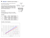
2-1. Volt-Ampere Curves
ssb1.1 10/91 − SA-166 690
The volt-ampere curves show the
minimum and maximum voltage
and amperage output capabilities of
the welding power source. Curves
of other settings fall between the
curves shown.
Figure 2-1. Volt-Ampere Curves
2-2. Duty Cycle
CAUTION
WELDING LONGER THAN RATED DUTY CYCLE can damage unit and void warranty.
• Do not weld at rated load longer than shown below.
warn7.1 8/93
Duty Cycle is percentage of 10
minutes that unit can weld at
rated load without overheating.
sb1.2* 8/93 − SB-136 510-A
0
10
Minutes
Definition Chart
60% Duty Cycle:
At 300 Amperes With Three-Phase Input Power,
At 225 Amperes With Single-Phase Input Power
6 Minutes Welding 4 Minutes Resting
Figure 2-2. Duty Cycle Chart

OM-299 Page 3
SECTION 3 − INSTALLATION
3-1. Typical Process Connections
Welding
Power Source
Work
Welding
GTAW
Power Source
Work
HF Unit
Remote
Control
GTAW
Pulse
Control
14 Pin
Welding
SMAW
Power Source
Work
Pulsed GTAW
Or
GTAW
14 Pin
Figure 3-1. Typical Process Connections
3-2. Selecting A Location And Moving Welding Power Source
WARNING
ELECTRIC SHOCK can kill.
• Do not touch live electrical parts.
• Disconnect input power conductors from de-
energized supply line BEFORE moving welding
power source.
FIRE OR EXPLOSION can result from
placing unit on, over, or near com-
bustible surfaces.
• Do not locate unit on, over, or near combustible
surfaces.
• Do not install unit near flammables.
BLOCKED AIRFLOW causes over-
heating and possible damage to unit.
• Do not block or filter airflow.
Warranty is void if any type of filter is used.
FUMES can be hazardous; LACK OF
FRESH AIR AND PROPER VEN-
TILATION can be harmful.
• Do not breathe welding fumes.
• Place unit only where there is a good fresh air supply
and proper ventilation.
FALLING EQUIPMENT can cause
serious personal injury and equipment
damage.
• Lift unit at handles.
• Have two persons of adequate physical strength lift
unit.
• Move unit with hand cart or similar device of ade-
quate capacity.
• If using a fork lift vehicle, secure unit on a proper skid
before transporting.
swarn11.1* 3/93

OM-299 Page 4
ssb9.1* 12/93 - ST-146 129-B / Ref. ST-151 556
1 Lifting Handles
Use handles to move unit.
2 Hand Cart
Use cart or similar device to move
unit.
3 Rating Label
Use rating label to determine input
power needs.
4 Line Disconnect Device
Locate unit near correct input pow-
er supply.
2
1
4
6 in
(156 mm)
3 in
(78 mm)
3 in
(78 mm)
3
Movement
Location And Airflow
Figure 3-2. Location And Movement Of Welding Power Source
3-3. Selecting And Preparing Weld Output Cables
1 Weld Output Cable
Determine total cable length in weld
circuit and maximum welding am-
peres. Use Table 3-1 to select prop-
er cable size.
Use shortest cables possible.
Do not use damaged cables.
2 Terminal Lug
Use lugs of proper amperage
capacity and hole size for connect-
ing to work clamp or electrode hold-
er.
3 Insulated Electrode Holder
4 GTAW Torch
Install according to manufacturer’s
instructions.
5 Work Clamp
Install onto work cable.
6 Dinse-Type Connector
Install onto weld cable as shown in
Figure 3-4.
Tools Needed:
10 ft (3 m)
10 ft (3 m)
sb6.2* 11/92 − S-0656
5
1
6
2
4
3
OR
Total Cable
Length In Weld
Circuit = 20 ft (6 m)
For Example,
Figure 3-3. Selecting And Preparing Weld Output Cables

OM-299 Page 5
1 Weld Output Cable
2 Handle
3 Sleeve
Slide handle onto cable; strip cable
and install sleeve.
4 Connector Body
5 Setscrew
Insert cable with sleeve fully into
connector body, tighten setscrew,
and slide handle over connector.
If job requires cable larger than 3/0
AWG, use 2 ft (610 mm) or shorter
piece of 3/0 AWG cable for Dinse-
Type connector installation. Con-
nect other end of short cable to the
4/0 or larger weld cable.
ST-156 496
Tools Needed:
1
2
3
1 in
(26 mm)
3
4
5
Figure 3-4. Dinse-Type Connector Assembly
Table 3-1. Weld Cable Size*
Total Cable (Copper) Length In Weld Circuit Not Exceeding
100 ft (30 m) Or Less
150 ft
(45 m)
200 ft
(60 m)
250 ft
(70 m)
300 ft
(90 m)
350 ft
(105 m)
400 ft
(120 m)
Welding
Amperes
10 To 60%
Duty Cycle
60 Thru 100%
Duty Cycle
10 Thru 100% Duty Cycle
100 4 4 4 3 2 1 1/0 1/0
150 3 3 2 1 1/0 2/0 3/0 3/0
200 3 2 1 1/0 2/0 3/0 4/0 4/0
250 2 1 1/0 2/0 3/0 4/0 2-2/0 2-2/0
300 1 1/0 2/0 3/0 4/0 2-2/0 2-3/0 2-3/0
350 1/0 2/0 3/0 4/0 2-2/0 2-3/0 2-3/0 2-4/0
400 1/0 2/0 3/0 4/0 2-2/0 2-3/0 2-4/0 2-4/0
500 2/0 3/0 4/0 2-2/0 2-3/0 2-4/0 3-3/0 3-3/0
*Weld cable size (AWG) is based on either a 4 volts or less drop or a current density of at least 300 circular mils per ampere. S-0007-D
3-4. Connecting To Weld Output Receptacles
WARNING
ELECTRIC SHOCK can kill; ARCING can burn skin or damage electrical equipment.
• Do not touch live electrical parts.
• Turn Off welding power source before making any weld output connections.
• Do not change position of welding cable connectors while welding.
• Be sure connectors are secure in receptacles before welding.
swarn12.2 2/93

OM-299 Page 6
1 Positive (+) Weld Output
Receptacle
2 Negative (−) Weld Output
Receptacle
3 Connector
For DC Electrode Positive (DCEP),
connect work cable connector to
negative (−) receptacle and elec-
trode holder cable connector to
positive (+) receptacle.
For DC Electrode Negative
(DCEN), reverse cable
connections.
To connect to receptacle, align key-
way, insert connector, and turn
clockwise until tight.
1 2
Ref. ST-153 618 / Ref. ST-152 223
3
Figure 3-5. Connecting To Weld Output Receptacles
3-5. Remote 14 Receptacle Information And Connections
sb7.1 12/93 − ST-800 695 / Ref. S-0004-A / S-0750
1 Remote 14 Receptacle RC2
(See Table 3-2)
2 Keyway
3 Plug
4 Threaded Collar
To connect to receptacle, align
keyway, insert plug, and tighten
threaded collar.
3
4
OR
AJ
B
K
I
C
L
NH
D
M
G
E
F
12
Figure 3-6. Remote 14 Connections
Table 3-2. Remote 14 Socket Information
A 24 volts ac. Protected by fuse F2.
B Contact closure to A completes 24 volts ac contactor control circuit.
C +10 volts dc output to remote control.
D Remote control circuit common.
E 0 to +10 volts dc input command signal from remote control.
K Chassis common.
Socket Information
*The remaining sockets are not used.
Socket*
AMPERAGE
A

OM-299 Page 7
3-6. Connecting Input Power
WARNING
ELECTRIC SHOCK can kill.
• Do not touch live electrical parts.
• Turn Off welding power source, and disconnect input power before inspecting or installing.
• Have only qualified persons install unit.
• Installation must meet National Electrical Code and all other codes.
swarn3.1 2/93
ssb2.3* 11/93 − Ref. SC-144 221 / Ref. SC-070 399-C / Ref. ST-146 129-B / S-0657 / Ref. S-0092-A
Have only qualified persons make
this installation.
1 Rating Label
Use single or three-phase, 50/60
Hz, ac input power which matches
one of the voltages shown. The AU-
TO-LINK circuitry senses the input
voltage and automatically links the
unit for operation.
2 Line Disconnect Device Of
Proper Rating
3 Input Power Cord
4 Grounding Conductor − Green
Or Green With Yellow
Stripe(s)
Install grounding conductor and
input conductors from unit to deen-
ergized line disconnect device.
Connect grounding conductor first,
then line input conductors.
Be sure grounding conductor goes
to an earth ground.
5 Black And White Input Con-
ductor
6 Insulation Sleeving
7 Electrical Tape
8 Red Input Conductor
Red conductor not used in single-
phase system. Insulate and isolate
conductor by sliding insulation
sleeving over end of lead, bending
lead back, and taping to power
cord.
9 Overcurrent Protection
Select type and size using
Table 3-3. Install into deenergized
line disconnect device (fused dis-
connect switch shown).
Three-Phase System Single-Phase System
44
2
2
9
9
OR
3
3
5
4
3
7
6
8
1
Figure 3-7. Location And Input Power Connections
Table 3-3. Electrical Service Requirements*
Three-Phase Single-Phase
Input Voltage
230 460 230 460
Input Amperes At Rated Output
42 21 50.8 29
Recommended Standard Fuse Or Circuit Breaker Rating In Amperes
1
60 30 80 40
*
These values are calculated from the 1993 edition of the National Electrical Code (NEC).
1 Recommended fuse or circuit breaker size is that closest to 150% of rated input amperage of the welding power source. Article 630-12(a) of NEC
allows fuse or circuit breaker sizing up to 200% of rated input amperage.
Ref. S-0092-G

OM-299 Page 8
SECTION 4 − OPERATION
WARNING
ELECTRIC SHOCK can kill.
• Always wear dry insulating gloves.
• Insulate yourself from work and ground.
• Do not touch live electrical parts.
• Keep all panels and covers securely in place.
FUMES AND GASES can be hazardous
to your health.
• Keep your head out of the fumes.
• Ventilate area, or use breathing device.
• Read Material Safety Data Sheets (MSDSs) and
manufacturer’s instructions for material used.
WELDING can cause fire or explosion.
• Do not weld near flammable material.
• Watch for fire; keep extinguisher nearby.
• Do not locate unit over combustible surfaces.
• Do not weld on closed containers.
• Allow work and equipment to cool before handling.
ARC RAYS can burn eyes and skin;
NOISE can damage hearing.
• Wear welding helmet with correct shade of filter.
• Wear correct eye, ear, and body protection.
MOVING PARTS can cause injury.
• Keep away from moving parts.
• Keep all doors, panels, covers, and guards closed
and securely in place.
MAGNETIC FIELDS FROM HIGH CUR-
RENTS can affect pacemaker operation.
• Pacemaker wearers keep away.
• Wearers should consult their doctor before going
near arc welding, gouging, or spot welding opera-
tions.
See Safety Precautions at beginning of manual for ba-
sic welding safety information.
swarn6.1 10/91
ST-152 224
1 Power Switch
2 Pilot Light
3 Amperage Control
4 Arc Force (Dig) Control
5 Output (Contactor) Switch
6 Amperage Control Switch
7 Process Selector Switch
8 Amperage/Voltage Meter And
Switch (Optional)
1
2
3
8
6
5
4
7
Figure 4-1. Controls
Wear the following while welding:
1 Dry, Insulating Gloves
2 Safety Glasses With Side
Shields
3 Welding Helmet With Correct
Shade Of Filter (See ANSI
Z49.1)
sb3.1 1/94
123
Figure 4-2. Safety Equipment

OM-299 Page 9
1 Work Clamp
Connect work clamp to a clean,
paint-free location on workpiece, as
close to weld area as possible.
Use wire brush or sandpaper to
clean metal at weld joint area. Use
chipping hammer to remove slag
after welding.
sb4.1 2/93
Tools Needed:
1
Figure 4-3. Work Clamp
Ref. SC-153 618
1 Process Selector Switch
Use switch to select type of weld
output. Use left position for
Shielded Metal Arc Welding
(SMAW). Use right position for Gas
Tungsten Arc Welding (GTAW).
Switch position determines the op-
eration of the Arc Force (Dig) con-
trol (see Figure 4-6).
1
Figure 4-4. Process Selector Switch
1 Amperage Adjustment Control
Use control to select weld amper-
age. Amperage may be adjusted
while welding.
1
Figure 4-5. Amperage Control
1 Arc Force (Dig) Control
This control is used for SMAW
welding and only works when Pro-
cess Selector switch (see Figure
4-4) is in the SMAW position.
Use control to help start an arc or
make vertical or overhead welds.
Control increases amperage at low
arc voltage (see Figure 2-1).
When set at 0, short-circuit amper-
age at low arc voltage is the same
as normal welding amperage.
When set at 100, short-circuit am-
perage at low arc voltage increases
to help arc starting.
Select setting best suited for appli-
cation. Numbers around control are
for reference only.
Set control at 0 for GTAW welding.
1
Figure 4-6. Arc Force (Dig) Control

OM-299 Page 10
WARNING
ELECTRIC SHOCK can kill.
• Do not touch live electrical parts.
• Do not touch weld output terminals when contactor is energized.
• Do not touch electrode and work clamp at the same time.
swarn7.1 10/91
1 Output (Contactor) Switch
Use switch to select way of control-
ling unit output.
For weld output, place switch in On
position.
For remote output control, place
switch in Remote 14 position (see
Section 3-5).
Weld output terminals are energized when switch is On and Power is On.
1
Figure 4-7. Output (Contactor) Switch
Example: Combination Remote Amperage Control
ST-159 059 / S-0769 / S-0774
1 Amperage Control Switch
Use switch to select way of control-
ling amperage.
For front panel control, place switch
in Panel position.
For remote control, place switch in
Remote 14 position (see Section
3-5).
Remote control at Remote 14 is
percent of front panel control
setting.
2 Fingertip Control
3 Remote Hand Control
4 Remote Foot Control
See example below.
4
Set Switches
Unit
Control Setting
Mimimum
2
3
1
(200 A)
Adjust Remote ControlSet Desired Maximum Amperage
Figure 4-8. Amperage Control Switch

OM-299 Page 11
1 Amperage/Voltage Meter
Use meter to read amperage and
voltage output. The preset value is
displayed when not welding.
When welding, the meter displays
weld amperage output of the unit if
amperage is selected. If voltage is
selected when welding, the meter
displays voltage at the weld output
terminals, but not necessarily the
welding arc due to cable resis-
tance, poor connections, etc.
The value displayed is held for 15
seconds after welding stops if the
hold function is On (see Section
5-4).
See table for the values displayed
for A/V switch settings.
2 Meter Switch
Use switch to select amperage or
voltage display.
1
2
A/V Switch
Meter Display
When Not
Welding
When
Welding
A
V
Actual Amps
Actual Volts
Preset Amps
Preset Amps
Positions
Figure 4-9. Amperage/Voltage Meter And Switch (Optional)
1 Power Switch
Use switch to turn unit and pilot light
On and Off.
There is a 5 second time delay be-
fore the unit is ready to weld.
Fan motor is thermostatically con-
trolled and only runs when cooling
is needed.
2 Pilot Light
1
2
Figure 4-10. Power Switch And Pilot Light
Turn On
Shielding Gas
ssb8.1* 12/92
Install &
Connect
Equipment
Install & Connect
High-Frequency
Unit
Select
Tungsten (See
Section 7)
Insert
Tungsten
Into Torch
Put On
Personal Safety
Equipment
Set Controls
Turn On
High-Frequency
Unit
Turn On
Welding Power
Source
Begin Welding
Figure 4-11. Sequence Of Gas Tungsten Arc Welding (GTAW)
Install &
Connect
Equipment
Install & Connect
Pulser Control
Unit
Install & Connect
High-Frequency
Unit
Insert
Tungsten
Into Torch
Put On
Personal Safety
Equipment
Set Controls
Turn On
Shielding Gas
Turn On
High-Frequency
Unit
Turn On
Welding Power
Source
Begin Welding
Turn On
Pulsing Control
Select
Tungsten (See
Section 7)
Figure 4-12. Sequence Of Gas Tungsten Arc Welding - Pulsed (GTAW-P)

OM-299 Page 12
Begin Welding
ssb7.1 9/92
Install &
Connect
Equipment
Select
Electrode
Put On
Personal Safety
Equipment
Set Controls
Insert
Electrode
Into Holder
Turn On
Welding Power
Source
Figure 4-13. Sequence Of Shielded Metal Arc Welding (SMAW)
SECTION 5 − MAINTENANCE & TROUBLESHOOTING
ELECTRIC SHOCK can kill;
SIGNIFICANT DC VOLTAGE exists after
removal of input power.
• Do not touch live electrical parts.
• Turn Off welding power source, disconnect input
power, wait 60 seconds, measure voltage on input
capacitors according to Section 5-2, and be sure
voltage is near zero before touching any parts.
HOT PARTS can cause severe burns.
• Allow cooling period before maintaining or servicing.
MOVING PARTS can cause injury.
• Keep away from moving parts.
STATIC ELECTRICITY can damage
parts on circuit boards.
• Put on grounded wrist strap BEFORE handling
boards or parts.
• Use proper static-proof bags and boxes.
Maintenance to be performed only by qualified persons.
WARNING
swarn8.3 2/94
5-1. Routine Maintenance
Turn Off all power before maintaining.
3 Months
Replace
Unreadable
Labels
Tape Or
Replace
Cracked
Cables
ST-146 129-B
Clean
And
Tighten Weld
Connections
6 Months
14-Pin Cord
Gas Hose Torch Cable
Replace
Cracked
Parts
3 Months
OR
During Heavy Service,
Clean Monthly
Blow Out
Or
Vacuum
Inside
Figure 5-1. Maintenance Schedule

OM-299 Page 13
5-2. Removing Case And Measuring Input Capacitor Voltage
READ SAFETY BLOCKS at start of
Section 5 before proceeding.
WARNING
Ref. ST-152 114-E
Turn Off welding power source and
disconnect input power.
1 Top Of Case
2 Handles
3 Outside Handle Screws
4 Side Bolts
To loosen top, remove two outside
handle screws from both handles
and all side bolts.
5 Bottom Of Case
6 Mounts
To loosen bottom, remove all side
bolts, carefully place unit on its side
and remove the four mounts.
7 Input Capacitors C12, C13
8 Input Capacitors C8, C9
Locate on lower left side.
9 Voltmeter
Check both sets of input
capacitors.
Measure dc voltage across positive
(+) and negative (−) terminals until
voltage drops to near 0 (zero) volts.
After task is completed, reinstall
case.
Tools Needed:
5/32 in
9
9
8
1
3
2
3
4
5
6
7
Front Panel
(Controls Vary
According To Model)
3/8, 7/16 in
Significant DC voltage can remain on capacitors after unit
is Off. Always check capacitors as shown to be sure they
have discharged before working on unit.
Figure 5-2. Removing Case And Measuring Input Capacitor Voltage

OM-299 Page 14
5-3. Overload Protection
READ SAFETY BLOCKS at start of
Section 5 before proceeding.
WARNING
A. Overheating
0
15
minutes
When overheated, thermostat
opens, output stops, and cooling
fan keeps running.
Let fan run for
15 minutes.
Start welding.
ssb10.1 1/94 − ST-146 129-B
Figure 5-3. Overheating
B. Fuses
ST-146 104-G / Ref. ST-146 102-F
Turn Off welding power source, dis-
connect input power, and check
voltage on input capacitors accord-
ing to Section 5-2 before
proceeding.
1 Fuse F2
If F2 opens, remote control devices
connected to Remote 14 recep-
tacle RC2 shut down.
Check fuse and replace as needed.
See Parts List for fuse size. Use
proper tool when removing fuse.
2 Fuse Holder
1
Tools Needed:
2
Figure 5-4. Overload Protection

OM-299 Page 15
5-4. Changing Amperage/Voltage Meter Hold Function
READ SAFETY BLOCKS at start of
Section 5 before proceeding.
WARNING
ST-159 050-A
The Amperage/Voltage meter is
able to hold the displayed weld out-
put value for 15 seconds after weld-
ing stops. If the hold function is not
used, the displayed value leaves
when welding stops.
This procedure allows the hold
function to be turned On or Off.
Turn Off welding power source, dis-
connect input power, and check
voltage on input capacitors accord-
ing to Section 5-2 before
proceeding.
1 Digital Meter Board PC5
2 DIP Switch S2
S2 is accessible from the left side of
the unit.
3 Toggle 1
4 Toggle 2
Set toggles in desired position.
Reinstall top of case.
Tools Needed:
1
12
12
Hold Used
Hold Not Used
4
ON
OFF
OFF
ON
2
3
Front Panel
(Controls Vary
According To Model)
Non-Conductive
Figure 5-5. Changing Amperage/Voltage Meter Hold Function
5-5. Troubleshooting
ELECTRIC SHOCK can kill.
SIGNIFICANT DC VOLTAGE exists after
removal of input power.
• Do not touch live electrical parts.
• Turn Off welding power source, disconnect input
power, wait 60 seconds, measure voltage on input
capacitors according to Section 5-2, and be sure
voltage is near zero before touching any parts.
HOT PARTS can cause severe burns.
• Allow cooling period before servicing.
MOVING PARTS can cause injury.
• Keep away from moving parts.
STATIC ELECTRICITY can damage
parts on circuit boards.
• Put on grounded wrist strap BEFORE handling
boards or parts.
• Use proper static-proof bags and boxes.
Troubleshooting to be performed only by qualified
persons.
WARNING
swarn9.3 2/94
Table 5-1. Welding Trouble
Trouble Remedy Section
No weld output; unit completely
inoperative.
Be sure Power switch is On. Figure 4-10
Be sure line disconnect switch is On. 3-6
Check line fuse(s) and replace if necessary. Reset circuit breakers. 3-6
Check for proper input connections. 3-6

OM-299 Page 16
Trouble Remedy Section
No weld output; fan motor FM running
and pilot light on.
Check position of Output (Contactor) switch. Figure 4-7
Thermostat TP1 open (overheating). Allow fan to run; thermostat
closes when unit has cooled.
5-3A
Low weld output with no control. Check position of Amperage Control switch. Figure 4-8
Have Factory Authorized Service Station/Service Distributor check
control board PC1.
− −
Limited output and low open-circuit
voltage.
Check incoming power for correct voltage. Replace line fuse if open
or reset circuit breaker.
3-6
Check for proper input and output connections. 3-3, 3-4, 3-6
Erratic or improper weld output. Tighten all welding cable connections. 3-3, 3-4
Check for proper size and type of cable. 3-3
Check for proper input and output connections. 3-3, 3-4, 3-6
Replace electrode. 7-1, 7-2
Remote device completely inoperative. Connect remote control to Remote 14 receptacle RC2. 3-5
Check fuse F2 and replace if necessary. 5-3B
Fan motor FM does not run after
approximately four minutes of operation
at rated load.
Have Factory Authorized Service Station/Service Distributor check
thermostats TP2 and/or TP3 and fan motor.
− −
Wandering arc; poor control of arc
direction.
Reduce flow rate. − −
Select proper size tungsten. 7-1
Properly prepare tungsten. 7-2
Tungsten electrode oxidizing and not re-
maining bright after conclusion of weld.
Shield weld zone from drafts. − −
Increase postflow time. − −
Check and tighten all gas fittings. − −
Water in torch. Refer to torch Owner’s Manual for part(s) requiring
replacement, and repair torch as necessary.
− −

OM-299 Page 17
NOTES

OM-299 Page 18
SECTION 6 − ELECTRICAL DIAGRAMS
Figure 6-1. Circuit Diagram For Welding Power Source
/