Page is loading ...

INSULATION-PIERCING TAP CONNECTORS
CONECTORES DE DERIVACIÓN QUE PERFORAN EL AISLAMIENTO
®
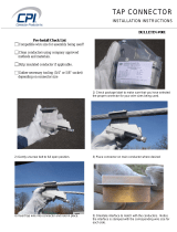
1. Determine the direction for the tap conductor to exit and
discard one end cap. See figure 1.
2. Position the main (or feeder) side of the connector around
the run cable and tighten the bolt finger tight. See
figure 2. If required, loosen the bolt slightly to allow the
connector to open completely. DISASSEMBLY NOT
RECOMMENDED. The plastic “Turbo” spacer holds the
connector open which eases installation and ensures proper
connections.
3. Cut the end of the tap cable squarely. DO NOT STRIP
CABLE INSULATION.
4. Insert the tap cable into the tap side of the connector until it
is seated in the remaining end cap. See figure 3.
5. Continue tightening the torque regulating bolt with a
standard box or socket wrench until the torque regulating
piece breaks away. If the connector has two (2) assembly
bolts, alternately tighten until the hexagonal torque devices
break away. See figures 4a & 4b. Note that the plastic
“turbo” spacer on the side will also break. To make the
installation even easier and to relieve torque from the
cables, a second wrench can be used on the hexagonal
piece on the bottom of the connector.
DO NOT use gripping type pliers, pipe, open ended
or adjustable wrenches as these may damage the
hexagonal torque regulating device. A torque wrench is not
required.
MAKE SURE ONLY THE TOP HEXAGONAL TORQUE
DEVICE OF THE BOLT HEAD IS USED FOR
ASSEMBLY. THE SECOND HEX PIECE [CLOSER
TO THE BODY OF THE CONNECTOR] IS USED FOR
DISASSEMBLY.
Note: The torque regulating bolt ensures the correct torque
is applied to the conductors without using a torque wrench.
Important information such as run and tap ranges, voltage
ratings and material/temperature ratings is marked on the
connector.
1. Determine la dirección en la que el conductor derivado saldrá y
deseche la tapa terminal sobrante. Vea la ilustración 1.
2. Coloque el lado principal (o de alimentación) del conector
alrededor del cual se hace la derivación y apriete firmemente
el dedo del perno. Vea la ilustración 2. Si hace falta, afloje
el perno ligeramente para permitir que el conector se abra
completamente. NO ES RECOMENDABLE DESARMAR EL
CONECTOR. El espaciador “Turbo” de plástico mantiene al
conector abierto, lo cual facilita la instalación y asegura que las
conexiones se hagan correctamente.
3. Corte el extremo del cable de derivación perpendicularmente a su
eje. NO PELE EL AISLAMIENTO DEL CABLE.
4. Inserte el cable de derivación en el lado de derivación del
conector hasta que tope contra la tapa terminal que queda. Vea la
ilustración 3.
5. Continué apretando este perno que regula la torsión con una
llave estándar o de cubo hasta que la pieza que regula la torsión
se parta y se separe. Si el conector tiene dos (2) pernos de
ensamblaje, apriételos alternativamente hasta que el dispositivo
de regulación de torción se parta. Vea la ilustración 4a y
4b. Observe que el espaciador “turbo” de plástico en el costado
también se fracturará. Para hacer esta instalación aún más fácil y
para aliviar la torsión de los cables, se puede usar una segunda
llave sobre la pieza hexagonal al fondo del conector.
NO USE alicates de presión, llaves de turbo, llaves
comunes o ajustables ya que éstas pueden dañar el
dispositivo hexagonal que regula la torsión. No se requiere una
llave de torsion.
ASEGÚRESE QUE SE USE, PARA EL ENSAMBLADO,
SÓLO EL DISPOSITIVO SUPERIOR DE REGULACION DE
TORSION DE LA CABEZA DEL PERNO. LA SEGUNDA
PIEZA HEXAGONAL (LA MÁS CERCANA AL CUERPO
DEL CONECTOR) SE USA SÓLO PARA DESARMAR EL
CONECTOR.
Nota: El perno regulador de torsión garantiza la aplicación de la
torsión correcta a lo s conductores sin usar una llave de torsión.
La información importante de longitud de cable pelado y de toma,
las clasificaciones de materiales y temperatura está marcada en el
conector.
figure 1
Before
Torque
Applied
figure 4a
After correct
Torque Reached,
One Hex Piece
Breaks-Away
figure 4b
figure 2
figure 3
Use sólo en cable aislado. [RHH, RHW(-2), THHN, THHW, THW,
THWN, USE, XHHW(-2). Consulte con la fábrica para obtener
información sobre otros tipos de aislamiento]. Si se va a hacer
la instalación sobre un cable con corriente el conductor derivado
debe estar libre de carga y no debe estar aterado. Use guantes
con aislamiento eléctrico. Quitele la corriente al cable del cual se
hace la derivación si no se pueden cumplir estas condiciones.
El
contacto con electricidad puede producir lesiones graves o mortales.
Installation Instructions: Instalación Instructiones:
Listed
486B
Pressure Cable Connectors
File No. E-5238
Improperly installed electrical wiring can be dangerous
and cause electrical fires. The connector chosen must
be sized to the wires being used. Consult local building
code before doing any electrical work. For assistance,
refer to an instructional book or consult a qualified
electrician.
Warning
Los cables eléctricos mal instalados pueden ser peligrosos
y provocar incendios. El conector escogido debe ser de un
tamaño adecuado para los cables que se utilicen. Consulte
los códigos de construcción locales antes de efectuar trabajos
eléctricos. Si necesita ayuda, consulte un libro de instrucciones
o consulte con un electricista capacitado.
Advertencia
Contact with electricity can cause serious injury or death.
Use on insulated cable only. [RHH, RHW(-2), THHN,
THHW, THW, THWN, USE, XHHW(-2). Consult factory
for other insulation types]. If the installation is to be
made on an energized run, the tap conductor must
be under no load and must not be grounded. Use
electrically insulated gloves. De-energize the run cable if
there are any questions of these conditions being met.
Warning
Advertencia

B-TAP
®
INSULATION PIERCING TAP CONNECTORS TORQUE AND
CURRENT RATINGS
(Solid and/or Stranded)
NOMINAL TAP CURRENT RATIING
CATALOG# MAIN TAP TORQUE (IN AMPS)*
BTC2/0-14 2/0-4 10-14
+
80 IN. LBS. 40
BTC1/0-10 1/0-8 2-10
++
80 IN. LBS. 130
BTC4/0-10 4/0-3 2-10
+++
125 IN. LBS. 130
BTC4/0-6 4/0-2 1/0-6 160 IN. LBS. 170
BTC4/0-2 4/0-2 4/0-2 160 IN. LBS. 260
BTC250-6 250-4 4/0-6 160 IN. LBS. 260
BTC250-4 250-1 3/0-4 160 IN. LBS. 225
BTC250-2 250-1/0 4/0-2 160 IN. LBS. 260
BTC350-1/0 350-1/0 350-1/0 330 IN. LBS. 350
BTC500-4 500-2/0 4/0-4 330 IN. LBS. 260
BTC500-1/0 500-4/0 350-1/0 330 IN. LBS. 350
BTC500-14 750-3/0 10-14
++++
80 IN. LBS. 40
BTC750-250 750-250 500-250 330 IN. LBS. 430
+10-14 Cu SOLID/STRANDED; 10-12 Al SOLID/STRANDED
++2-10 Cu SOLID/STRANDED; 2-10 Al STRANDED
+++2-10 Cu SOLID/STRANDED; 2-8 Al STRANDED
++++10-14 Cu SOLID/STRANDED; 10-12 Al STRANDED
Full line is 600V dual-rated, 194°F(90°C)
* Based on NEC Table 310-16 1996 (Not more than 3 insulated conductors in a raceway at ambient temperature of 30° C) for the largest tap wire size.
ND 9053-1
1839420
WARNING: Cancer and Reproductive Harm - www.P65Warnings.ca.gov.
ADVERTENCIA: Cáncer y Daño Reproductivo - www.P65Warnings.ca.gov.
One year limited warranty. See idealind.com for more information.
Garantía limitada de un año. Visite www.idealind.com para obtener detalles de la garantía.
1800 S. Prairie Drive
Sycamore, IL, U.S.A.
800-435-0705 • www.idealind.com
/