Page is loading ...

Introducing the LCD TV
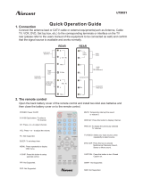
Using the LCD TV
Installing the LCD TV
37 LCD TV
User Guide
TV/CATV
TV
AT
SC
FOR ATSC DTV
VIDEO
COMP.
PC
-
+
1
2
3
4
5
6
7
8
9
00
0
MENU
AUTO
CH-
MUTE
PICTURE SWAP SOUND
WIDE PIP POP DIGEST
ZOOM WINDOW
DISP
V-CHIP
C.C.
MTS
SET UP EPG C.C.
FAV- FA
V+ FAV EDIT STILL
AUDIO
SLEEP
SKIP
POWER
CH+
VO
L-
VO
L+
ENTER
CH RTN

1
FCC
ENGLISH
Federal Communications Commission Statement
This equipment has been tested and found to comply with the limits of a class B digital device,
pursuant to Part 15 of the FCC Rules. These limits are designed to provide reasonable protection
against harmful interference in a residential installation. This equipment generates, uses and can
radiate radio frequency energy and, if not installed and used in accordance with the instructions, may
cause harmful interference to radio communications. However, there is no guarantee that
interference will not occur in a particular installation. If this equipment does cause harmful
interference to radio or television reception, which can be determined by turning the equipment off
and on, the user is encouraged to try to correct the interference by one or more of the following
measures:
1. Reorient/Relocate the receiving antenna.
2. Increase the separation between the equipment and receiver.
3. Connect the equipment into an outlet on a circuit which is different from what the receiver is
connected to.
4. Consult the dealer or an experienced radio/TV technician for help.
Changes or modifications not expressly approved by the manufacturer
responsible for compliance could void the user authority to operate the
equipment.

2
Warnings and Precautions
Warnings and Precautions
To reduce the risk of fire or electric shock, do not expose this equipment to rain or moisture.
This symbol is intended to alert the user to avoid the risk of electric shock.
This equipment must not be disassembled by anyone except qualified service
personnel.
This symbol is intended to alert the user to the presence of important
operating and maintenance instructions in the literature accompanying the
appliance.
▪ TO REDUCE THE RISK OF ELECTRIC SHOCK,
▪ DO NOT REMOVE COVER (OR BACK).
▪ NO USER-SERVICEABLE PARTS INSIDE.
▪ REFER SERVICING TO QUALIFIED SERVICE PERSONNEL.
Use of controls, adjustments or performance of procedures other than those specified herein
may result in hazardous radiation exposure.
CAUTION
Important Safety Instructions
To prevent any injuries, the following safety precautions should be observed in the installation, use,
servicing and maintenance of this equipment.
Before operating this equipment, please read this manual completely, and keep it nearby for future
reference.
WARNING
▪ Do not place the equipment on any uneven or unstable carts, stands, tables, shelves etc.
The equipment may fall, causing serious injury to children or adults and serious damage
to the equipment itself.
▪ Use only a cart or stand recommended by the manufacturer. This equipment and
recommended cart or stand should be handled with care. Quick stops, excessive force,
and uneven surfaces may cause the equipment and cart/stand to overturn.
▪ Do not disable the 3-wire grounding type plug. The grounding pin on the 3-prong plug is
an important feature. Removing the grounding pin will increase the risk of damaging the
equipment.
▪ If you can not fit the plug into the electrical outlet, contact an electrician to install a
grounding outlet.
▪ Always operate this equipment from the type of power source indicated on the rear of the
serial/model plate.
▪ Never overload wall outlets and extensions.
▪ Use and handle the power cord with care. Do not place any heavy objects on the AC
power cord.
▪ Do not pull the AC power cord. Do not handle the AC power cord with a wet hand.
▪ Do not touch the power cord and antenna cable during lightning.

3
Warnings and Precautions
ENGLISH
▪ Remove the plug from the wall outlet, if the equipment will not be used for a long period
of time.
▪ Do not place, use or handle this equipment near water.
▪ Never expose the equipment to liquid, rain, or moisture.
Seek for service if any of the above is spilled into the equipment.
▪ Do not expose the equipment to extreme temperature or to direct sunlight, as the
equipment may heat up and suffer damage.
▪ Do not install the equipment near any heat sources such as radiators, heat registers,
stoves, or any other apparatus that might produce heat.
▪ Do not attempt to service the equipment yourself.
▪ Opening and removing the covers may expose you to dangerous voltage or other
hazards and may void your warranty. Refer service to qualified personnel.
▪ Do not place or drop any other objects on top.
▪ Do not insert anything into the ventilation holes of your equipment.
Inserting any metal or flammable objects may result to fire or electric shock.
▪ Do not place the equipment on uneven or unstable carts, stands, tables, shelves etc. The
equipment may fall, causing serious injury to children or adults and serious damage to
the equipment itself.
Always place the equipment on the floor or on a surface that is sturdy, level, stable and
strong enough to support the weight of the equipment.
▪ Do not block any ventilating openings. Leave an open space around the equipment.
Never place the equipment :
on a bed, sofa, rug, or any other similar surfaces; too close to drapes/curtains/walls, in a
bookcase, built-in cabinet, or any other similar places that may cause poor ventilation.
▪ Always remove the power cord from the outlet before cleaning the equipment.
▪ Never use liquid or aerosol cleaners on the equipment.
Clean only with a soft dry cloth.

4
Warnings and Precautions
Outdoor Antenna Safety Instructions
Antenna lead-in wire
Antenna discharge unit
(NEC section 810-20)
Grounding conductors
(NEC section 810-20)
Ground clamps
Power service grounding
(NEC Art250 part H)
Ground clamps
Electric service
equipment
NEC : National Electrical code
If an outdoor antenna is connected, follow the precautions below:
EXAMPLE OF OUTDOOR ANTENNA GROUNDING
Section 810 of National Electrical Code (NEC) provides information with respect to proper grounding of the
mast and supporting structure, grounding of the lead-in wire to an antenna discharge unit, size of grounding
conductors, location of antenna discharge unit, connection to grounding electrodes, and requirements for
the grounding electrode.
▪ An outdoor antenna should not be located in any area where it could come in contact with
overhead power lines, or any other electric light or power circuits.
▪ When installing an outdoor antenna system, extreme caution should be taken to prevent
contact with power lines. Direct contact with power lines may be fatal and should be avoided
at all costs.

5
Troubleshooting and Specifications
ENGLISH
CONTENTS
Warnings and Precautions
Important Safety Instructions ......................................................................................... 2
Antenna Safety Instructions ........................................................................................... 4
Chapter 1 Introducing the LCD TV
Key Features ................................................................................................................. 7
Package Contents ......................................................................................................... 8
Setting Your LCD TV ...................................................................................................... 9
Your LCD TV .................................................................................................................. 10
Your Remote Control ..................................................................................................... 12
Chapter 2 Installing the LCD TV
Connecting a TV Cable or Antenna ............................................................................... 14
Connecting a VCR ......................................................................................................... 18
Connecting a DVD Player .............................................................................................. 19
Connecting a TV Cable Box and Satellite Receiver ...................................................... 21
Connecting a Video Camera .......................................................................................... 23
Connecting a two VCRs ................................................................................................ 24
Connecting a PC ........................................................................................................... 25
Chapter 3 USING THE FEATURES
Watching Your LCD ....................................................................................................... 26
Operating the Menu ....................................................................................................... 27
Setting up the Channel List ................................................................................. 28
Customizing the Picture Settings ......................................................................... 32
Customizing the Audio Settings ........................................................................... 34
Customizing the Picture Color Settings ................................................................. 35
Customizing the Display Settings ......................................................................... 36
Customizing the OSD Settings ............................................................................ 37
Customizing the MISC Settings ........................................................................... 38
Using the PIP/POP/DIGEST Settings ................................................................... 39
Using the V-CHIP Settings (For U.S TV system only) ............................................. 40
Operating the ATSC System ............................................................................... 43
Customizing the STATION Settings ...................................................................... 45
Customizing the LOCK Settings ........................................................................... 46
Customizing the CAPTION Settings ..................................................................... 47
Customizing the SETUP Settings ......................................................................... 48
TROUBLESHOOTING ............................................................................................ 49
SPECIFICATION .................................................................................................... 50
Federal Communications Commission Statement

6
Chapter 1 Introducing the LCD TV

7
Chapter 1 Introducing the LCD TV
ENGLISH
Various Audio/Video terminals for external equipment connection
▪ 2 composite A/V input terminal
▪ 1 set of composite A/V output terminals
▪ 2 S-VIDEO terminal
▪ 2 set of component Video input terminals
▪ 1 VGA/AUDIO input terminal
▪ 1 HDMI/AUDIO input terminal
▪ 4 sets of Audio input terminals
High Definition Multimedia Interface (HDMI)
▪ High Definition Multimedia Interface (HDMI) is a small, user-friendly interconnect that
can carry up to 5 Gbps of combined video and audio in a single cable. This system
eliminates the cost, complexity and confusion of multiple cables used to connect
current A/V systems
The built-in TV tuner to receive HD ATSC
▪ This function allows the reception of HD broadcasting without the addition of a set top
box.
Digital Noise Reduction
▪ This function can digitally reduce image noise to provide better picture quality.
Film-Mode Detection (3:2 Reverse Pull Down)
▪ This function can automatically detect content derived from film and adjust the
interlacer’s frame matching to provide a more natural-looking, clearer image of the
moving picture.
PIP Function
▪ This function allows viewing of video from two different sources simultaneously.
The input source of the main window can be one of VGA, HDMI, YPbPr1, YPbPr2, ATSC and
the input source of sub window will be one of AV1/2, S-VIDEO1/2, and TV.
Compatible with HDTV, available for 480p, 720p and 1080i HDTV video signals
Chapter 1 Introducing the LCD TV
Key Features

8
Chapter 1 Introducing the LCD TV
LCD TV
Make sure all of the following contents are included.
If you are missing any items, please return this product to the original place of purchase.
User Guide
Power Cord
Remote Control/AAA Batteries x 2
These items are all you need to set up and operate the LCD TV in its basic
configuration.
Most devices (VCRs, DVD players etc.) come with the necessary cables for
connection. If you want to set up a complex system, you may need to purchase
extra cables, connectors etc.
Package Contents
Antenna Jack (ATSC and NTSC)
TV/CATV
TV
ATSC
FOR ATSC DTV
VIDEO
COMP.
PC
-
+
1
2
3
4
5
6
7
8
9
00
0
MENU
AUTO
CH-
MUTE
PICTURE SWAP SOUND
WIDE PIP POP DIGEST
ZOOM WINDOW
DISP
V-CHIP
C.C.
MTS
SET UP EPG C.C.
FAV- FAV+ FA
V EDIT STILL
AUDIO
SLEEP
SKIP
POWER
CH+
VOL-
VOL+
ENTER
CH RTN
Warranty Card

9
Chapter 1 Introducing the LCD TV
ENGLISH
Use a supplied antenna cable to connect the VHF/UHF signal to the LCD TV’s ANT. terminal
(refer to page14-17).
Connect the AC power cord at the back of the TV and connect t the power cord to wall
outlet.
Insert the 2 batteries supplied in remote control.
Step1 Slide the back cover up to
open the battery
compartment of the remote
control.
Do not use caustic cleaners (porcelain, stainless steel, toilet, or oven cleaner
etc.) on the remote, as it may suffer damage.
Connect other an external A/V device (refer to page18-25).
Setting Your LCD TV
Step2 Insert two AAA size batteries.
Make sure to match the (+) and
( - ) ends of the batteries with
the (+) and ( - ) ends indicated
in the battery compartment.
Slide the cover back into place.

10
Chapter 1 Introducing the LCD TV
Your LCD TV
LED
The LED light indicates when
the LCD TV is activated.
IR
Infrared Receiver
MENU
Press once to display the OSD (on screen display),
press again to turn the OSD off.
VOLUME▲▼
Adjusts the volume up and down. Selects the main-menu
item and change values for items when in the OSD mode.
Turns the LCD TV on and into standby mode.
SELECT▲▼
Scans up and down through channels. Selects sub-
menu item when in the OSD mode.
SOURCE
Chooses from different input signal sources.
Front/Side View and Controls

Pb Pr
Pb Pr
VG
A
HDMI
S-VIDEO1 AV1
VIDEO
NTSC
ATSC
S-VIDEO2AV2
11
Chapter 1 Introducing the LCD TV
ENGLISH
Rear View and Jacks
ANT. ATSC
Connects RF input from VHF/UHF antenna or cable to receive high definition digital television.
AV Output
Connects to the composite A/V intput jacks on external video equipment.
AV1/S-VIDEO1 IN
Connects to the composite Video/S-VIDEO and Audio output
jacks on external video equipment.
COMPONENT(YPbPr2) IN
Connects to the Component(YPbPr) video and audio output
jacks on external video equipment.
AV2/S-VIDEO2 IN
Connects to the composite Video/S-VIDEO and Audio output jacks on external
video equipment.
COMPONENT(YPbPr1) IN
Connects to the Component(YPbPr) video and
audio output jacks on external video equipment.
ANT. NTSC
Connects RF input from VHF/UHF antenna or cable.
VGA IN
Connects the satellite receiver or other AV equipment, TV Box, or
PC with VGA connector.
HDMI AUDIO IN
Connects the AV equipment with AUDIO jack of HDMI (The AUDIO of
HDMI IN is for DVI connection).
HDMI IN
Connects the AV equipment with HDMI connector.
VGA AUDIO IN
Connects the satellite receiver or other AV equipment, TV Box, or PC
with AUDIO jack of VGA.

TV/CATV
TV
AT
SC
FOR ATSC DTV
VIDEO
COMP.
PC
-
+
1
2
3
4
5
6
7
8
9
00
0
MENU
AUTO
CH-
MUTE
PICTURE SWAP SOUND
WIDE PIP POP DIGEST
ZOOM WINDOW
DISP
V-CHIP
C.C.
MTS
SET UP EPG C.C.
FAV- FA
V+ FAV EDIT STILL
AUDIO
SLEEP
SKIP
POWER
CH+
VO
L-
VO
L+
ENTER
CH RTN
12
Chapter 1 Introducing the LCD TV
CH RTN
Switch back and forth between the
current and previous channel.
Your Remote Control
Turns the LCD TV on and off.
DISP
Displays information on the LCD TV
screen such as channel and channel
label.
SLEEP
Sets the LCD TV sleep time.
TV/VIDEO/COMP./PC
Selects among the video equipment
connected to the video inputs of
your LCD TV.
ATSC DTV FUNCTION
For ATSC TV system only.
SOUND
Cycles through the audio modes:
STANDARD, MOVIE, SOFT
MUTE
Mutes and restores your LCD TV sound.
CH+/-
Scans up and down through channels.
VOL+/-
Adjusts the volume.
MENU
Displays the OSD (on screen
display) menu.
AUTO
Automatically detect and store all
active channels in your ares.
0-9
Select and switch to a channel
by using 0-9 buttons.
00
The one/two digit numbers by
pressing this button.
C.C.
Cycles through the closed caption
modes.
WINDOW
Controls or adjusts either the main
screen and sub screen in PIP/POP
mode.
V-CHIP
Turns the V-CHIP function on and off.
PICTURE
Cycles through picture quality modes:
STANDARD, BRIGHT, SOFT, MOVE
STANDARD, MOVE BRILLIANT
Effective range:
The remote can control the LCD TV from up to 5m away, if pointed directly at the receiver.
SWAP
Swaps between main and sub
screens in PIP/POP/DIGEST mode.
MTS
Cycles through the TV Sound
options: MONO/SAP/Stereo
TV/CATV
Cycles through the TV receiving signal:
TV(antenna), CATV(cable)
WIDE
Cycles through the picture size:16:9,4:3,
FULL,NATIVE
PIP/POP/DIGEST
Enters picture-in-picture(PIP)/
picture-outside-picture(POP)/
multiple pictures(DIGEST) modes
ENTER
Refers to the OSD menu for
detailed information.
SKIP
Deletes the current channel.
ZOOM
Enters the enlarge funciton,press
+/- buttons to adust the screen size
gradually.
-+
Changes the size of secondary picture
while using the window button.

TV/CATV
TV
AT
SC
FOR ATSC DTV
VIDEO
COMP.
PC
-
+
1
2
3
4
5
6
7
8
9
00
0
MENU
AUTO
CH-
MUTE
PICTURE SWAP SOUND
WIDE PIP POP DIGEST
ZOOM WINDOW
DISP
V-CHIP
C.C.
MTS
SET UP EPG C.C.
FAV- FA
V+ FAV EDIT STILL
AUDIO
SLEEP
SKIP
POWER
CH+
VO
L-
VO
L+
ENTER
CH RTN
13
Chapter 2 Installing the LCD TV
ENGLISH
ATSC
Select the ATSC TV receiving the
signal inputs of your LCDTV.
ATSC DTV FUNCTION
SETUP
In ATSC TV mode, pressing SETUP
displays the menu on the screen.
EPG
In ATSC TV mode, pressing
EPG displays the EPG
(Electronic Program Guide) on
the screen.
C.C.
In ATSC TV mode, cycles
through the digital Closed
Caption.
FAV-/FAV+
Change the favorite channel up and
down.
AUIDO
In ATSC TV mode, allows to select
the audio language: English/French/
Spanish
FAV EDIT
Edit the favorite channel.
STILL
No function

14
Chapter 2 Installing the LCD TV
Chapter 2 Installing the LCD TV
Refer to the owner’s manual of any external equipment to be connected.
When connecting any external equipment, do not connect any AC power cords to wall outlets until all
other connections are completed.
Connecting a TV Cable or Antenna
Antenna Connection
The antenna requirements for good color TV reception are more important than those for a black &
white TV reception. For this reason, a good quality outdoor antenna is strongly recommended.
The following is a brief explanation of the type of connection that is provided with the various antenna
systems.
75-ohm coaxial cable (round)
F-type connector
300-ohm twin-lead cable (flat)
■ A 75-ohm system is generally a round cable (not included) with F-
type connector that can easily be attached to a terminal without
tools.
■ A 300-ohm system is a flat twin-lead cable (not included) that can
be attached to a 75-ohm terminal through a 300-75-ohm adapter
(not included).
Use one of the following two diagrams when connecting an outdoor antenna.
A: Shows how to use a VHF/UHF combination outdoor antenna.
B: Shows how to use a separate VHF and/or UHF outdoor antenna.

15
Chapter 2 Installing the LCD TV
ENGLISH
OUT
IN
300-ohm twin-
lead cable
300-ohm twin-
lead cable
75-ohm
coaxial cable
UHF
Antenna
VHF
Antenna
Combiner
(not included)
A. Combination VHF/UHF antenna
300-ohm twin-
lead cable
75-ohm
coaxial cable
VHF/UHF
Antenna
VHF/UHF
Antenna
300/75-ohm adapter
(not included)
B. Separate VHF and/or UHF antennas
ANT.
ANT.

16
Chapter 2 Installing the LCD TV
This reminder is provided to call the CATV system installer’s attention to Article 820-40 of the
National Electrical Code (NEC) that provides guidelines for proper grounding and, in particular,
specifies that the cable ground shall be connected to the grounding system of the building
accurately, or as close to the point of cable entry as possible. Use of this TV for other than
private viewing of programs broadcasted on UHF, VHF or transmitted by cable companies for
the use of the general public may require authorization from the broadcast/cable company, and/
or program owner.
A
IN
B
OU
T
Cable TV Line
2 set signal
splitter
(not included)
RF switch
(not included)
Cable TV converter/
descrambler
(not included)
Cable TV (CATV) Connection
■ The RF switch (not included) is required to provide two inputs (A and B). Setting
the RF switch to position A allows viewing of all unscrambled channels by using
the TV channel keys.
■ Setting the RF switch to position B allows viewing of all scrambled channels via
the converter/descrambler by using the converter channel keys.
■ A 75-ohm coaxial cable connector is built into the set for easy hookup.
When connecting the 75-ohm coaxial cable to the set, connect the 75-
ohm cable into the ANT. terminal.
■ Some cable TV companies offer premium pay channels. Since the
signals of these premium pay channels are scrambled, a cable TV
converter/descrambler is generally provided to the subscriber by the
cable TV company.
This converter/descrambler is necessary for normal viewing of scrambled channels.
(Set your TV to channel 3 or 4, typically one of these channels is used. If this is unknown,
consult your cable TV company.)
For more specific instructions on installing cable TV, consult your cable TV company.
One possible method of connecting the coverter/descrambler provided by your cable TV
company is shown in the diagram below.

17
Chapter 2 Installing the LCD TV
ENGLISH
Use a supplied antenna cable to connect the ANT.NTSC or ANT.ATSC signal to the LCD
TV’s ANT. terminal.
Connect the AC power cord at the back of the TV and connect the power cord
to wall outlet.
Press the button on the remote to turn on the LCD TV.
Press the TV button on the remote.
Always disconnect the LCD TV from the main voltage when the LCD TV will
not be used for a long period of time. The POWER button on the front panel
is only used for switching the LCD TV into standby, it does not disconnect
the device from the main voltage. To completely disconnect the main
voltage, please remove the power plug from the socket.
ATSC
NTSC

18
Chapter 2 Installing the LCD TV
METHOD A:
Use an S-Video cable to connect the VCR’s S-video output jack to the LCD TV’s S-
VIDEO1 or S-VIDEO2 input jack. Use an audio cable to connect the VCR’s audio
output jacks to the LCD TV’s audio inputs.
METHOD B:
Use a composite cable to connect the VCR’s composite video/audio jacks to the LCD TV’s
composite video/audio AV1 or AV2 jacks.
Connect all AC power sources, before turning on the power switch of the LCD TV or
other connected equipment.
Press the button on the remote to turn on the LCD TV.
To watch a videotape, press the VIDEO button on the remote repeatedly to select
S-VIDEO1/S-VIDEO2( METHOD A), or AV1/AV2 (METHOD B).
Connecting a VCR
S-VIDEO2AV2
Pb Pr
Pb Pr
VG
A
HDMI
S-VIDEO1 AV1
VIDEO
NTSC
ATSC
A
B

19
Chapter 2 Installing the LCD TV
ENGLISH
Pb Pr
Pb Pr
VG
A
HDMI
S-VIDEO1 AV1
VIDEO
NTSC
ATSC
Connecting a DVD Player
METHOD A:
Use a HDMI cable to connect the DVD’s HDMI jack to the LCD TV’s HDMI jack.
METHOD B:
Use a component cable to connect the DVD player’s component output jacks to the LCD TV’s
component (YPbPr1 or YPbPr2) input jacks. Use an audio cable to connect the DVD player’s
component audio jacks to the LCD TV’s audio input jacks.
METHOD C:
Use an audio cable to connect the DVD’s audio output jacks to the LCD TV’s audio
inputs. Use an S-Video cable to connect the DVD’s S-video output jack to the LCD TV’s
S-video1 or S-video2 input jack.
METHOD D:
Use a composite cable to connect the DVD’s composite video/audio jacks to the LCD TV’s
AV1 or AV2 jacks.
DVD PLAYER
S-VIDEO2AV2
C D
/Pr
/Pb
B
/Pr
/Pb
A
/