GRASS VALLEY CopperHead PowerWafer User guide
- Category
- Supplementary music equipment
- Type
- User guide
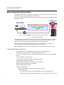
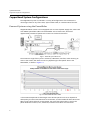
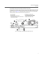
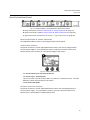
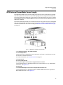
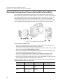
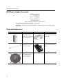
GRASS VALLEY CopperHead PowerWafer is a fiber optic transmission system that enables camcorders to be used in live, multi-camera production environments. The system uses a fiber optic cable to transport a variety of signals between a Camera Unit and a Base Station. The CopperHead Camera Unit is typically mounted to a camera that is placed in a studio, theatre, sports venue, or other live-event location. The system's Base Station is usually located in a truck, control room or other video production control area.
GRASS VALLEY CopperHead PowerWafer is a fiber optic transmission system that enables camcorders to be used in live, multi-camera production environments. The system uses a fiber optic cable to transport a variety of signals between a Camera Unit and a Base Station. The CopperHead Camera Unit is typically mounted to a camera that is placed in a studio, theatre, sports venue, or other live-event location. The system's Base Station is usually located in a truck, control room or other video production control area.


-
 1
1
-
 2
2
-
 3
3
-
 4
4
-
 5
5
-
 6
6
-
 7
7
-
 8
8
-
 9
9
-
 10
10
-
 11
11
-
 12
12
-
 13
13
-
 14
14
-
 15
15
-
 16
16
-
 17
17
-
 18
18
-
 19
19
-
 20
20
-
 21
21
-
 22
22
-
 23
23
-
 24
24
-
 25
25
-
 26
26
-
 27
27
-
 28
28
-
 29
29
-
 30
30
-
 31
31
-
 32
32
-
 33
33
-
 34
34
-
 35
35
-
 36
36
-
 37
37
-
 38
38
-
 39
39
-
 40
40
-
 41
41
-
 42
42
-
 43
43
-
 44
44
-
 45
45
-
 46
46


GRASS VALLEY CopperHead PowerWafer User guide
- Category
- Supplementary music equipment
- Type
- User guide
GRASS VALLEY CopperHead PowerWafer is a fiber optic transmission system that enables camcorders to be used in live, multi-camera production environments. The system uses a fiber optic cable to transport a variety of signals between a Camera Unit and a Base Station. The CopperHead Camera Unit is typically mounted to a camera that is placed in a studio, theatre, sports venue, or other live-event location. The system's Base Station is usually located in a truck, control room or other video production control area.
Ask a question and I''ll find the answer in the document
Finding information in a document is now easier with AI
Related papers
Other documents
-
PT PT600R Mains Power Module Owner's manual
-
 Telecast CopperHead 3400 User manual
-
JVC GY-HD250U User manual
-
 Telecast KA-PW790VG User manual
-
Crosman 781 (1983-Present) Owner's manual
-
-
-
-
-

