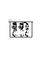
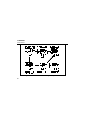
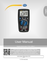
Fluke Weather Radio PN 2063508: This handheld device is most likely used by professionals like electricians or technicians who work with electrical systems. It's capable of measuring voltage, continuity, and resistance, and can also test diodes and capacitance. It has an easy-to-read display and is also equipped with a continuity beeper for quick and easy identification of continuity in circuits.
Fluke Weather Radio PN 2063508: This handheld device is most likely used by professionals like electricians or technicians who work with electrical systems. It's capable of measuring voltage, continuity, and resistance, and can also test diodes and capacitance. It has an easy-to-read display and is also equipped with a continuity beeper for quick and easy identification of continuity in circuits.


-
 1
1
-
 2
2
-
 3
3
-
 4
4
-
 5
5
-
 6
6
-
 7
7
-
 8
8
-
 9
9
-
 10
10
-
 11
11
-
 12
12
-
 13
13
-
 14
14
-
 15
15
-
 16
16
-
 17
17
-
 18
18
-
 19
19
-
 20
20
-
 21
21
-
 22
22
-
 23
23
-
 24
24
-
 25
25
-
 26
26
-
 27
27
-
 28
28
-
 29
29
-
 30
30
-
 31
31


Fluke Weather Radio PN 2063508: This handheld device is most likely used by professionals like electricians or technicians who work with electrical systems. It's capable of measuring voltage, continuity, and resistance, and can also test diodes and capacitance. It has an easy-to-read display and is also equipped with a continuity beeper for quick and easy identification of continuity in circuits.
Ask a question and I''ll find the answer in the document
Finding information in a document is now easier with AI
Related papers
-
Fluke 114 Electrical Multimeter User manual
-
Fluke 87 TRUE RMS MULTIMETER User manual
-
-
-
Fluke 83 User manual
-
-
-
-
-
Other documents
-
 PCE Health and Fitness PCE-HDM 7 User manual
-
KRAFTWERK 31130 Operating instructions
-
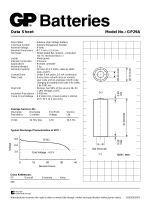 GP Batteries 29A Datasheet
-
Wavetek PM51 Owner's manual
-
Magnum MS8268 Operator's Instruction Manual
-
Mastech MS8217 User manual
-
Extech Instruments MG302 User manual
-
Agilent Technologies 34401A User manual
-
-
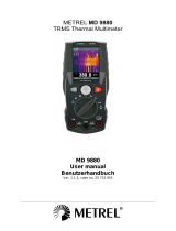 METREL MD 9880 User manual


