Page is loading ...

INSTRUCTIONS for INSTALLATION
and USE
Gas Hob
BG05
To the Installer
Before installation fill in the product details on the back cover of this
booklet. The information can be found on the rating plate.
To the User
You must read the instructions prior to using the appliance and then
retain them for future reference.
This appliance must be installed in accordance with
regulations in force and only in a well ventilated place.
Ensure that the hob unit is securely fixed to the worktop
before use.
FP087-01 HP Gas Hob (BG05) 12/09/2001 4:59 pm Page 1

Introduction 3
CONTENTS
For Your Safety – Always 4
For Your Safety – Never 5
Installation 9 - 14
Using The Hob 6
Care & Cleaning 7
Something Wrong? 8
Hotpoint Service Cover 15
Key contacts Back Cover
2
Retention of this Instruction Book
This Instruction Book must be kept handy for reference as it contains important
details on the safe and proper use of the appliance.
If you sell or pass the appliance to someone else, or move house and leave it
behind, make sure this Book is also provided so the new owner can become
familiar with the appliance and safety warnings.
If the Book is lost or damaged a copy may be obtained from
GDA Ltd, Morley Way, Peterborough, PE2 9JB.
FP087-01 HP Gas Hob (BG05) 12/09/2001 4:59 pm Page 2
INTRODUCTION
Your new hob is guaranteed* and will give lasting service. This guarantee is only
applicable if the appliance has been installed in accordance with the installation
instructions detailed in this booklet.
To help make best use of your cooking equipment,
please read this booklet carefully.
The hob is designed specifically for domestic use and responsibility will not be
accepted for use in any other installation.
* The guarantee is subject to the provisions that the appliance:
(a) Has been used solely in accordance with the Users Instruction Book.
(b) Has been properly connected to a suitable supply voltage and gas supply
as stated on the rating plate attached to this equipment.
(c) Has not been subjected to misuse or accident or been modified or
repaired by any person other than the authorised employee or agent.
(d) Has been correctly installed.
3
FP087-01 HP Gas Hob (BG05) 12/09/2001 4:59 pm Page 3

FOR YOUR SAFETY
When used properly, your appliance is completely safe but as with any
product there are certain precautions that must be observed.
PLEASE READ THE PRECAUTIONS BELOW BEFORE USING YOUR
APPLIANCE.
ALWAYS
●
Always make sure you understand the controls prior to using the appliance.
●
Always keep children away from the appliance when in use as the surfaces will get
extremely hot during and after cooking.
●
Always make sure all controls are turned off when you have finished cooking and
when not in use.
●
Always take care to avoid heat/steam burns when operating the controls.
●
Always turn off the electricity supply at the wall switch and allow the appliance to cool
before cleaning .
●
Always keep the appliance clean as a build up of grease or fat from cooking can
cause a fire.
●
Always follow the basic principles of food handling and hygiene to prevent the
possibility of bacterial growth.
●
Always refer servicing to a qualified appliance service engineer.
●
Always dry food thoroughly before frying, and lower it slowly into the hot oil or fat.
Frozen foods, in particular, will cause frothing and spitting, if added too quickly.
●
Always keep the outside of the pan clean and free from streaks of oil or fat.
●
Always place pans centrally over the burner making sure handles are kept away from
the edge of the hob and cannot become heated by other burners / pans.
SAFETY ADVICE
IMPORTANT - As with any cooking appliance there could be some fire risk attached to
the heating of oil, particularly for deep fat frying. Cooking utensils containing oil must not
be left unattended (e.g. to answer the telephone) on or in close proximity to the cooking
areas.
IN THE EVENT OF A CHIP PAN OR ANY OTHER PAN FIRE:
1. TURN OFF THE BURNERS.
2. COVER THE PAN WITH A FIRE BLANKET OR DAMP CLOTH, this will smother the
flames and extinguish the fire.
3. LEAVE THE PAN TO COOL FOR AT LEAST 60 MINUTES BEFORE MOVING IT.
Injuries are often caused by picking up a hot pan and rushing outside with it.
NEVER USE A FIRE EXTINGUISHER TO PUT OUT A PAN FIRE as the force of the
extinguisher is likely to tip the pan over. Never use water to extinguish oil or
fat fires.
.
4
FP087-01 HP Gas Hob (BG05) 12/09/2001 4:59 pm Page 4

NEVER
●
Never leave children unsupervised where a cooking appliance is installed as all
cooking surfaces will be hot during and after use.
●
Never allow anyone to sit or stand on any part of the appliance.
●
Never store items above the appliance that children may attempt to reach.
●
Never leave anything on the hob surface when unattended and not in use.
●
Never heat up unopened food containers as pressure can build up causing the
container to burst.
●
Never store chemicals, food stuffs or pressurised containers in or on the
appliance, or in cabinets immediately above or next to the appliance.
●
Never place aluminium or plastic foil or plastic containers directly on the hob
surface.
●
Never fill a deep fat frying pan more than 1/3 full of oil, or use a lid. DO NOT
LEAVE UNATTENDED WHILE COOKING.
●
Never use the appliance as a room heater.
●
Never dry any items on the hob.
●
Never use misshapen pans which may be unstable.
●
Never use round base woks directly on the pan supports.
●
Never use fish kettles or large preserving pans across two burners.
NOTE: The use of a gas cooking appliance results in the production of heat and moisture in the
room in which it is installed. Always ensure that the kitchen is well ventilated; keep natural
ventilation holes open or install a mechanical ventilation device (mechanical extractor hood).
In particular, when using the grill or more than one hotplate burner, open a window if a
mechanical ventilation device is not operating.
FOR YOUR SAFETY
5
FP087-01 HP Gas Hob (BG05) 12/09/2001 4:59 pm Page 5
USING THE GAS HOB - FEATURES
6
DO NOT allow young children near to the appliance when the hob is in
use as the surfaces get extremely hot.
In order to obtain maximum performance from the burners, use pans with the
following diameters:
Rapid burner 22 - 28 cm
Standard burner 14 - 22 cm
Auxillary burner 10 - 14 cm
All pans should be positioned centrally over the burners.
OPERATION WHEN USING THE GAS HOB
Step 1 Check that the electricity is switched ON.
Step 2 Press the ignition button and then push and turn the control knob of the
chosen burner anticlockwise to the large flame symbol. The gas should
then ignite.
Step 3 Turn the control knob anticlockwise to the desired setting. Only turn the
control knob between the large flame symbol and the small flame
symbol when adjusting the setting.
Step 4 Place the pan centrally on the required burner.
Step 5 To switch off, turn the control knob fully clockwise.
FP087-01 HP Gas Hob (BG05) 12/09/2001 4:59 pm Page 6

Clean the hob regularly and wipe up spills soon after they occur to prevent them from
becoming burnt on.
1. Household abrasive powders, e.g. Vim.
2. Oven chemical cleaners, aerosols and oven pads.
Caustic cleaners such as these will etch the surface and attack the metal frame.
3. Bath and sink cleaners may mark the surface.
Wipe with a cloth wrung out in hot soapy water. Stubborn stains can be removed with
a cream paste or liquid cleaner.
Wipe with a cloth wrung out in hot soapy water followed by a wipe with a cloth wrung
out in clear water and then dried with a soft clean cloth.
Wipe with a cloth wrung out in hot soapy water only; do not use abrasives. Use a
nylon brush to remove any cleaning materials, water or dirt from the burner bodies.
Re-assemble as in the diagram below.
Wipe over the knobs with a soft cloth wrung out in hot soapy water or mild non-abra-
sive cleaner. Then, after wiping with a cloth wrung out in clear water, dry with a soft
clean cloth.
Never use scouring pads or abrasive cleaners/powders which may scratch the
surface.
CARE AND CLEANING
SWITCH OFF THE ELECTRICITY SUPPLY BEFORE CLEANING.
BEFORE SWITCHING ON AGAIN, ENSURE THAT ALL
CONTROLS ARE IN THE OFF POSITION.
NEVER USE BIOLOGICAL WASHING POWDER, HARSH
ABRASIVES, SCOURING PADS, AEROSOL CLEANERS OR
OVEN CHEMICAL CLEANERS OF ANY KIND.
CLEANING MATERIALS TO AVOID
7
CONTROL KNOBS.
ALUMINIUM BURNER BODIES AND RINGS.
VITREOUS ENAMEL HOB, PAN SUPPORTS AND BURNER CAPS.
STAINLESS STEEL.
BURNER ASSEMBLY
FP087-01 HP Gas Hob (BG05) 12/09/2001 4:59 pm Page 7

8
This appliance conforms to the following EEC Directives:
Low Voltage Equipment
73/23/EEC
93/68/EEC
Electromagnetic Compatibility
89/336/EEC
92/31/EEC
93/68/EEC
Gas Appliances
90/396/EEC
93/68/EEC
To minimise the risk of injury to children please dispose of your product carefully
and safely. Remove all doors and lids (where fitted). Remove the mains cable
(where fitted) by cutting off flush with the appliance and always ensure that no plug
is left in a condition where it could be connected to the electricity supply.
To help the environment, Local Authority instructions should be followed for the
disposal of you product.
Disposal of your product
Is the electricity switched on?
If the electricity supply has failed, the burners can be lit with a match.
If only a hotplate burner is failing to ignite, check that the burner body and cap are
seated correctly and that the slots in the burner body are not blocked (see care
and cleaning).
IF THE IGNITION DOES NOT WORK
May we wish you many years of carefree successful cooking.
SOMETHING WRONG ?
FP087-01 HP Gas Hob (BG05) 12/09/2001 4:59 pm Page 8
INSTALLATION - electrical requirements
9
Connection to the electricity supply should be made via a properly earthed, readily accessible
wall socket which is adjacent to but not directly above, and not more than 1.25m away from the
appliance and capable of electrical isolation.
Should this plug not fit the socket outlet in your home it should be cut off and replaced with a
suitable plug as outlined below.
NOTE: The removed plug cannot be used for any other appliance and should therefore be
properly disposed of and not left where children might find it and plug it into a supply
socket – with the obvious consequent danger.
IF THE FITTED PLUG IS REMOVED
The flexible mains lead must be correctly connected as below to a three pin plug of not less
than 13 amp capacity. If a B.S. 1363 fused plug is used, it must be fitted with a 3 amp fuse which
is approved to B.S. 1362.
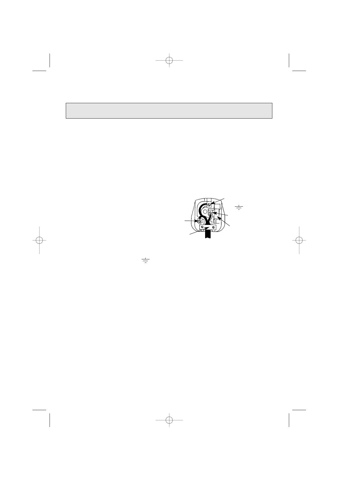
IMPORTANT: The wires in the mains lead fitted to
this appliance are coloured in
accordance with the following code:
GREEN AND YELLOW – EARTH
BLUE – NEUTRAL
BROWN – LIVE
As the colours of the wires in the mains lead of this appliance may not correspond with the
coloured markings identifying the terminals in your plug, proceed as follows:– The wire which is
coloured green and yellow must be connected to the terminal in the plug which is marked with
the letter E or by the earth symbol or coloured green or green and yellow. The wire which is
coloured blue must be connected to the terminal which is marked with the N or coloured black.
The wire which is coloured brown must be connected to the
terminal which is marked with the letter L or coloured red. When wiring the plug, ensure that all
strands of wire are securely retained in each terminal. Do not forget to tighten the mains lead
clamp on the plug. As the appliance must be earthed, do not use 2-pin
sockets outlets, if you are in doubt, consult a qualified electrician.
Should the mains lead ever require replacement, it is essential that this operation be
carried out by a qualified electrician and should only be replaced with a flexible cord of the
same size i.e. 0.75mm
2
cross sectional area and temperature rating of 85
0
C e.g. heat resisting
PVC.
IF A MOULDED PLUG IS FITTED
In the event of replacing a fuse in the plug supplied a 3 amp ASTA approved fuse to BS1362
must be fitted.
NOTE: The fuse cover must be refitted when changing the fuse. In the event of losing the
fuse cover the plug must not be used until a replacement fuse cover has been obtained and
fitted. A new fuse cover can be obtained from your local Electricity Board. The colour of the
correct replacement fuse cover is that of the coloured marks or inserts in the base of the plug.
Make sure that the cable does not become trapped.
WARNING – THIS APPLIANCE MUST BE EARTHED.
CONNECT TO A 230-240V A.C. SUPPLY ONLY.
Green &
Yellow to
Earth
Brown to
Live
Blue to
Neutral
Cord Clamp
3 Amp
Fuse
FP087-01 HP Gas Hob (BG05) 12/09/2001 4:59 pm Page 9

INSTALLATION INSTRUCTIONS
10
Gas Connection
Pressure test point
Aeration adjustment
Electrical Connection
Rp
1
/
4
(
1
/
4
” BSP female)
Burner injector
None
230-240V ac. 50Hz Heat resistant PVC 85
o
C 0.75mm2 Flexible
cord.
Model Numbers W810, BG05
These models are set to burn NATURAL GAS (G20) at 20mbar.
They can also be converted to burn BUTANE GAS (G30) at 28mbar or PROPANE
GAS (G31) at 37mbar using the conversion kit included.
Gas Category II2H3+ (GB,IE)
Technical Data
BURNER
HEAT INPUT
INJECTOR
Natural Gas
Front Left
Rear Right
and Rear Left
Front Right
3.0 kW
2.0 kW
1.15kW
130
105
80
HEAT INPUT
INJECTOR
LPG
3.0 kW
2.0 kW
1.15kW
92
72
55
FP087-01 HP Gas Hob (BG05) 12/09/2001 4:59 pm Page 10

GAS SAFETY (INSTALLATION & USE) REGULATIONS
LOCATION
PROVISION FOR VENTILATION
INSTALLATION INSTRUCTIONS
11
Prior to installation, ensure that the local distributions (nature of the gas and gas
pressure) and the adjustment conditions are compatible. The adjustment conditions
for this appliance are stated on the rating plate which is fitted on the underside of
the base panel. This appliance is not designed to be connected to a combustion
products evacuation device. It must be installed and connected in accordance with
current installation regulations. Particular attention should be given to the relevant
requirements regarding ventilation.
It is the law that all gas appliances are installed by competent persons in accordance
with the current edition of the above regulations. It is in your interest and that of
safety to ensure compliance with the law.
In the UK, CORGI registered installers work to safe standards of practice.
The cooker must also be installed in accordance with BS 6172:
Failure to install the cooker correctly could invalidate the warranty liability claims and
could lead to prosecution.
The cooker may be located in a kitchen, kitchen/diner or a bed-sitting room, but not
in a room containing a bath or shower. The cooker must not be installed in a bed-
sitting room of less than 20m
3
.
The room containing the cooker should have an air supply in accordance with BS
5440: Part 2.
The room must have an opening window or equivalent; some rooms may also
require a permanent vent. If the room has a volume between 5 and 10m
3
, it will
require an air vent of 50cm
2
effective area unless it has a door which opens directly
to outside. If the room has a volume of less than 5m
3
, it will require an air vent of
100cm
2
effective area. If there are other fuel burning appliances in the same room,
BS 5440: Part 2 should be consulted to determine air vent requirements.
FP087-01 HP Gas Hob (BG05) 12/09/2001 4:59 pm Page 11

The hob is designed to fit into worktop and base unit(s) with a cutout as shown in
Fig.1. Any obstruction such as supports or side panels must be removed to allow
30mm minimum depth below the worktop cutout. Any overhead surface of
combustible material must not be closer than 600mm. When installing next to a tall
cupboard, partition or wall, for a minimum distance of 400mm above the hotplate a
side clearance of at least 40mm should be allowed from the edge of the cutout. This
is a type X appliance regarding installation requirements, it is recommended that a
shelf is fitted to the cabinet under the hob, but no closer than 10mm to prevent
access to the underside of the hob which will become hot when in use.
If a cooker hood is to be installed refer to the manufacturer’s instructions regarding
fixing heights.
Unpack the hob from the carton.
Remove the bag containing the sealing tape, fixing brackets, screws and gas inlet
elbow.
Fit the sealing tape around the edge of the cut-out in the worktop.
Connect the gas inlet elbow supplied to the end of the hob gas pipe. During
installation, it is important not to twist the hob gas pipe when connecting to or
adjusting the position of the gas inlet elbow to avoid the possibility of disturbing gas
tight joints inside the hob. Ensure that the inlet is held securely:
* When loosening or tightening the hob gas pipe securing nut.
* When connecting fittings to it.
Also, ensure that connecting pipe work does not twist the inlet elbow away from its
free position.
Lower the hob into the worktop ensuring the mains lead is fed into the base unit and
is not trapped under the flanges.
Fix the hob to the worktop using the fixing brackets and screws.
NB Do not over tighten the hob clamps as distortion of the hob may occur.
Connect the hob to the gas supply and check for gas soundness. If a flexible hose is
used for connection, it should be fitted such that it cannot come into contact with
moveable parts of the housing (e.g. a drawer), does not pass through a space where
it is likely to become trapped or damaged and hangs freely downwards. The tem-
perature rise of the area of the base panel likely to come into contact with a flexible
hose does not exceed 70ºC
Connection must be by rigid pipework when the hob is installed above an oven.
Put the burner rings and caps into position.
Connect the hob to the electrical supply (see INSTALLATION - Electrical
Requirements).
Ensure that the hob is functioning correctly prior to use. Instruct the user in the
operation of the hob.
SITING THE HOB
FITTING THE HOB
INSTALLATION
12
FP087-01 HP Gas Hob (BG05) 12/09/2001 4:59 pm Page 12

13
INSTALLATION
Fig. 1
IMPORTANT
Minimum unobstructed depth
50mm
Worktop thickness
Preferred 30-40mm
19mm minimum
recommended
30mm
489mm
558mm
Front edge
of worktop
Note: Do not over tighten the hob clamps as distortion of the hob may occur.
Fig. 2
FIXING CLAMP
FP087-01 HP Gas Hob (BG05) 12/09/2001 4:59 pm Page 13
INSTALLATION INSTRUCTIONS
14
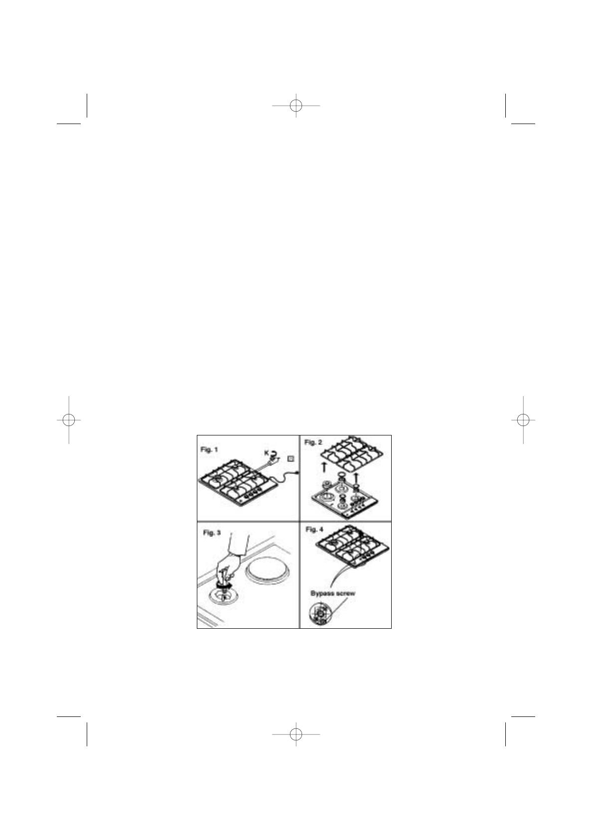
Read the Gas Hob instructions before conversion, installation and using the Gas
Hob.
1 Rapid burner injector marked 92 - 1 off
2 Semi-rapid burner injector marked 72 - 2 off
3 Auxillary burner injector marked 55 - 1 off
Ensure that the Gas Hob is disconnected from the gas and electricity supply (Fig.1)
1. Remove pan supports, burner caps,burner bodies and control knobs (Fig.2)
2. Remove each injector and replace with LPG injector using 7mm A/F hexagonal
socket (Fig.3).
3. Turn each gas tap bypass screw fully clockwise using a small flat bladed
screwdriver through the holes in the control panel.
The bypass screw is located to the side of the tap spindle (Fig.4).
LPG Conversion Instructions for Models W810, BG05
Hotplate Burner Injector Change and Bypass Screw Adjustment
Contents of kit:
FP087-01 HP Gas Hob (BG05) 12/09/2001 5:00 pm Page 14

Satisfaction Guaranteed or Your
Money Back
Hotpoint gives you a unique ‘Satisfaction
Guaranteed’ promise – valid for ninety days after
you have purchased your Hotpoint product. If there is
a technical problem with your Hotpoint appliance, just
call Hotpoint Service (see back page). If necessary we
will arrange for an engineer to call. If the technical
problem is not resolved under this Guarantee,
Hotpoint will replace your appliance or, if you prefer,
give you your money back. Your statutory rights are
not affected, and the Guarantee is additional and sub-
ject to the terms of Hotpoint’s Five Year Parts
Guarantee.
Hotpoint’s Free Five Year Guarantee
From the moment your appliance is delivered
Hotpoint guarantees it for FIVE YEARS.
• In the Five Years all replacement parts are FREE
provided that they are fitted by our own
Service Engineer. During the first year our
Engineer’s time and labour is also free.
• Our guarantee covers loss of food in our
refrigeration and freezer products up to £250
during the first year, subject to verification by
one of our engineers.
• After the first year we will charge for our
Engineer’s time and labour. We do, however,
operate a range of Service Plans (see opposite)
which, for an annual payment, enables you to
cover any repair costs which may be necessary.
• All our service repairs are guaranteed for
twelve months in respect of our labour and any
parts fitted.
• The appliance must be used in the United
Kingdom, and must not be tampered with or
taken apart by anyone other than our own
Service Engineers.
• You may, however, buy parts which can be
safely fitted without specialist knowledge or
equipment. The correct fitting of such parts,
provided they are genuine Hotpoint spares, will
not affect your Guarantee. Parts are available
from our Hotpoint Spares Centres (see back
page).
• Our guarantee does not cover the cost of any
repair, or loss of food in refrigeration products,
due to power failure, accidents or misuse. Nor
does it cover the cost of any visits to advise
you on the use of your appliance. Please read
thoroughly the instruction book supplied with
this appliance.
• If at any time during the Guarantee period we
are unable to repair your appliance, we will
refund any repair costs paid to us in the
previous twelve months. We will also offer you
a new appliance at a reduced charge instead of
a repair.
• Our Guarantee is in addition to and does not
affect your legal rights.
• Should you need independent advice on your
consumer rights, help is available from your
Consumer Advice Centre, Law Centre, Trading
Standards Department and Citizens Advice
Bureau.
• All Hotpoint servicing is carried out by our own
Service Organisation located throughout the
United Kingdom and Eire. We will be happy to
deal with any problems which you may have.
Hotpoint’s Extended Warranties
Whether you have just one or a number of Hotpoint
appliances in your kitchen, Hotpoint has a range of
Service Plans to give you complete peace of mind.
They enable you to extend your one year labour
guarantee so that you can have repairs completed
FREE during the membership period.
Service Cover
We offer a number of payment methods; cheque,
credit card or you can spread the cost and pay by
direct debit (full details can be obtained on Free
phone 0800 716356). This covers you for all repairs
during the period of cover, which can be from 1 to 4
years. Service Cover also includes loss of food, up
to the value of £250, in refrigeration appliances.
There is also an option of Service Cover with
Maintenance at an additional cost. This includes an
annual Electrical and Safety check and replacement
of any parts as necessary.
Kitchen Cover
An annual payment covers you for all repairs for all
your Hotpoint appliances which are less than ten
years old. It also covers the cost of loss of food up
to £250 in our refrigeration and freezer products.
There is also the option of Kitchen Cover with
Maintenance at an additional cost. Any additional
Hotpoint appliances purchased after you have joined
Hotpoint Kitchen Cover will automatically be includ-
ed during the annual period of cover without further
charge.
Appliance Registration
To ensure that you have the opportunity to benefit
from any of the above Service Schemes and other
offers you should complete and return immediately
the Appliance Registration Form/Questionnaire sup-
plied with this appliance. Full details and costs of our
Service Schemes, together with an application form,
will be sent to you at the end of the first year of the
guarantee.
Annual Safety/Maintenance Checks
Hotpoint strongly recommends that all its
appliances are regularly checked for electrical and
mechanical safety, whether or not they are covered
by a Service Plan. Worn door gaskets or hoses may
cause a leak on an appliance, which could become
dangerous if neglected.
Proof of Purchase
For future reference please attach your purchase
receipt to this booklet and keep it in a safe place.
Spares and Accessories
Spares and accessories can be ordered from your
local Hotpoint Spares Centre (see back page), using
the order form enclosed.
NOTE: Our Engineers will use every effort to avoid
damage to floor coverings and adjacent units when
carrying out repairs/service work, but in locations
where the Engineer advises you that it will be impos-
sible to move appliances without risk of
damage, he will only proceed with your approval
that no liability is accepted.
Hotpoint Service Cover
15
FP087-01 HP Gas Hob (BG05) 12/09/2001 5:00 pm Page 15

FP087 - 01
Key Contacts
Service
Hotpoint has the largest appliance manufacturer’s service team in
Europe, trained specialists directly employed by us to ensure your
complete confidence.
Repair Service
UK: 08709 066 066
Republic of Ireland: 1850 302 200
You will be asked for the following information:-
Name, address and postcode.
Telephone number
Model / Serial number of the appliance
Clear and concise details of the query or fault
Place and Date of purchase
(Please keep the receipt as evidence will be required when the engineer calls).
Extended Warranty
To join: UK 08709 088 088
Republic of Ireland: 1850 502 200
Genuine Parts & Accessories
Mail Order Hotline
UK: 08709 077 077
Republic of Ireland: (01) 842 6836
For further product information
08701 506070
All Hotpoint Services are offered as an extra benefit and do not affect your statutory rights.
General Domestic Appliances Limited, Morley Way, Peterborough, PE2 9JB
FP087-01 HP Gas Hob (BG05) 12/09/2001 5:00 pm Page 16
/