Page is loading ...

(MODEL NUMBER:AC-16652)

SAFETY PRECAUTIONS
1
WARNING
To reduce the risk of personal injury,
do not bend the blades when installing
the blades, balancing the blades or
cleaning the fan. Do not insert foreign
objects between rotating fan blades.
WARNING
The box must be supported directly by
the building structure. The box and its
support
must be able support the fan
weight - must not twist or work loose.
Do not use plastic boxes.
WARNING-INSTALLATION SHOULD BE PERFORMED BY A QUALIFIED
ELECTRICAN
1. To ensure the success of the installation, be sure to read the instructions and review
the diagrams thoroughly before beginning.
2. All electrical connections must be in accordance with local codes, ordinances or
National Electrical Code. If you are unfamiliar with methods of installing
electrical wiring secure the services of a qualified electrician.
3. Make sure that your installation will not allow rotating fan blades to come in
contact with any object.
4. If you are installing more than one ceiling fan, make sure that you do not mix fan
blade sets.
5. Only mount fan to outlet box marked acceptable for ceiling fan.
6. Installation to a concrete ceiling should be performed by a qualified electrician.
7. Before beginning, disconnect power by removing fuse or turning off circuit
breaker.
8. After fan is completely installed, make sure that all connections are secured to
prevent fan from falling.
9. Do not insert anything into the fan blades while ceiling fan is operating.
10. Fan must be turned off and stopped before reversing fan direction.
11. The fan must be mounted with the blades at least 2.3m from the floor to minimum
the possibility of accidental contact with the fan blades.
12. The supply wires Live & Neutral must be connected to wall switch (double poles)
having a contact separation at least 3mm in all poles.

Putting Your Fan Together
Hanging Your Ceiling Fan
1. Insert the downrod through the center
opening in the canopy and route the
motor leads through the hanger ball/
downrod assembly. Align the clevis pin
holes in the downrod with the holes in
the motor coupling. The clevis pin must
pass through the holes in the motor
coupling and the downrod. Place the
washer onto the clevis pin and install the
hairpin clip making sure to push straight
leg of the hairpin clip through the hole
near hanger ball to make sure the clevis
pin is properly installed (see Fig.1)
2. Remove the 2 set screws in the motor
coupling and securely tighten screws
against the downrod assembly.
Securely attach the hanger bracket to the
outlet box by washers and screws supplied
(see Fig.2)
1.
Carefully lift the fan and seat the downrod
and ball assembly on the hanger bracket.
Be sure the groove in the ball is lined up
with tab on the hanger bracket. (see Fig.
3)
2.
Install the safety cable into the building
structure (see Fig.4)
3.
FIG.2
FIG.3
FIG.4
FIG.1
CLEVIS
PIN
HAIR PIN
CLIP
COUPLING
SCREW
WASHER
CANOPY
HANGER
BALL
OUTLET
BOX
HANGER
BRACKET
WASHER
WASHER
HANGER
BRACKET
SAFETY
CABLE
SPRING
WASHER
HANGER
BRACKET
DOWNROD
DOWNROD
WASHER
SCREW
SCREW
2

Wiring Your Ceiling Fan
Installing Blade Assembly
Installing The Switch Housing
1. If you are not sure that the electrical box
is grounded, contact a licensed electrician
for advice. It must be grounded for safe
operation.
2. Connect the black wire from the outlet
box to the black and blue wire from fan
with wire nut. Connect the white wire
from outlet box to the white wire from
fan with wire nut. Connect the green wire
from the outlet box to the green wire from
the fan (see Fig.5)
3. Loosen the two canopy mounting screws
from the hanger bracket. Mount the canopy
on the two screws in the hanger bracket
and twist the canopy, so the screw heads
hold the canopy in place. Retighten the
two screws (see Fig.6)
Install the screw, washer, blade and blade
bracket together & tighten them securely
(see Fig.7)
1.
Attached each blade assembly to the fan
body using the blade screws. Tighten them
securely (see Fig.8)
2.
Connect the plug from the fan and switch
housing (see Fig.9)
1.
FIG.6
FIG.7
FIG.8
FIG.9
FIG.5
HANGER
BRACKET
CANOPY
SCREW
BLADE
BRACKET
BLADE
SCREW
SCREW
PLUG
SWITCH
HOUSING
SCREW
SWITCH COVER
BLADE
WASHER
SCREW
WHITE
WHITE
BLACK
BLACK
BLUE
GROUND
GROUND
3
Caution : To avoid possible electrical
shock, be sure electricity is turned off at
the main fuse box before wiring.

FIG.10
4
The light pull chain has two positions. One
pull turns the light on, two turns the light
kit off. The fan pull chain has four posit-
ions. One pull is high, two is medium, th-
ree is low and four to turn it off. (see Fig.10)
LIGHT
PULL
CHAIN
SPEED PULL
CHAIN
REVERSE
SWITCH

Operation in Summer
In warm weather, the reverse switch should
be set to produce a downward flow of air.
The constant, gentle breeze will transfer
heat from your body; thus, you will feel
cooler even if the temperature remains
unchanged. This cooling effect is referred
to as a wind-chill factor. In an air-
conditioned home, the wind-chill factor
will allow you to set the thermostat higher
than the usual setting. While using less
energy to air-condition your home, you
will stay just as cool.
For summer cooling, set the speed control
on medium or fast speed. This will
provide sufficient airflow to accomplish a
cooling effect. The exception to this is in
bedrooms where a brisk, downward flow
would be too chilly. A low-speed, gentle
breeze is all that is necessary to keep you
comfortable at night.
Operating in Winter
Winter comfort requires a different
approach. Because warm air rises the air
close to the ceiling is always warmer-by
perhaps 15 degrees-than the air close to the
floor. To prevent heat from hovering
where it does little good, move the reverse
switch to create an upward airflow. This
will pull cool air up and force warm air
across the ceiling and down the walls. Set
the variable speed control fast enough to
break up the air stratification, but slow
enough not to create a draft. By keeping
the heat circulating, the heater will not
have to operate as often to keep you warm.
5

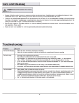
CARE OF YOUR FAN
Here are some suggestions to help you maintain your fan.
1. Because
of the fan's natural movement, some connections may become loose. Check the support
connections, brackets, and blade attachments twice a year. Make sure they are secure. (It is
not necessary to remove fan from ceiling.)
2. Clean your fan periodically to help maintain its new appearance over the years. Use only a soft
brush or lint-free cloth to avoid scratching the finish. The plating is sealed with a lacquer to
minimize discoloration or tarnishing. Do not use water when cleaning. This could damage the
motor, or the wood, or possibly cause an electrical shock.
3. You
can apply a light coat of furniture polish to the wood blades for additional protection and
enhanced beauty. Cover small scratches with a light application of shoe polish.
4. There is no need to oil your fan. The motor has permanently lubricated sealed ball bearings.
6

TROUBLESHOOTING
Problem
Fan will not start
.
Fan sounds noisy.
Remote control
malfunction.
Lights shut off and will
not come back on.
Fan wobble.
Solutio
n
1. Check main and branch circuit fuses or breakers
.
2.
Check line wire connections to the fan and switch wire connections in the
switch housing.
3. Check to make sure the dip switches from the transmitter and receiver are
set to the same frequency.
1. Make sure all motor housing screws are snug.
2. Make sure the screws that attach the fan blade bracket to the motor hub are
tight.
3. Make sure wire nut connections are not rattling against each other or the
interior wall of the switch housing.
4. Allow a 24-hour "breaking-in" period. Most noises associated with a new fan
disappear during this time.
5. If using ceiling fan light kit, make sure the screws securing the glassware
are tight. Check that the light bulb is also secure.
6. Make sure there is a short distance from the ceiling to the canopy. It should
not touch the ceiling.
7. Make sure your ceiling box is secure and rubber isolator pads are used
between mounting bracket and outlet box.
1. Do not connect the fan with a wall mounted variable speed control(s).
2. Make sure the dip switches are set correctly.
1. This unit may be equipped with a wattage limiting device. Lamping in
excess of 190 watts will disable your ceiling fan's light kit. To reset your light
kit you must turn the power off and relamp, keeping the wattage under 190
watts. Restore power to your ceiling fan and continue normal operation.
1. Check that all blade and blade arm screws are secure.
2. Most fan wobbling problems are caused when blade levels are unequal.
Check this level by selecting a point on the ceiling above the tip of one of
the blades. Measure this distance. Rotate the fan until the next blade is
positioned for measurement. Repeat for each blade. The distance deviation
should be equal within 1/8".
3. Use the enclosed Blade Balancing Kit if the blade wobble is still noticeable.
4.
If the blade wobble is still noticeable, interchanging two adjacent (side by
side) blades can redistribute the weight and possibly result in smoother
operation.
WARNING
: TO REDUCE THE RISK OF PERSONAL INJURY, DO NOT
BEND THE BLADE ARM WHILE INSTALLING, BALANCING THE BLADES,
OR CLEANING THE FAN. DO NOT INSERT FOREIGN OBJECTS
BETWEEN ROTATING FAN BLADES.
TNA11112123
/