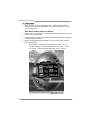
Biostar NF3 Owner's manual
- Category
- Motherboards
- Type
- Owner's manual
This manual is also suitable for

NF3 250 AM2 Setup Manual
FCC Information and Copyright
This equipment has been tested and found to comply with the limits of a Class
B digital device, pursuant to Part 15 of the FCC Rules. These limits are designed
to provide reasonable protec tion against harmful interference in a residential
installation. This equipment generates, uses and can radiate radio frequency
energy and, if not installed and used in accordance with the instructions, may
cause harmful interference to radio communications. There is no guarantee
that interference will not occur in a particular ins talla tion.
The ve ndor makes no representa tions or warranties with respec t to the
contents here and specially disclaims any implied warranties of merchantability
o r fi tness fo r a ny purp ose . F urt he r the ve nd o r rese rves t he ri ght to rev is e t his
publication and to make changes to the contents here without obligation to
notify any party beforehand.
D uplication of this publication, in part or in whole , is not allowed without first
obtaining the vendor’s approval in writing.
The content of this user’s manual is subject to be changed without notice and
we will not be res ponsible for any mistakes found in this user’s manual. All the
brand and product names are trademarks of their respective companies.

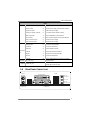
Table of Contents
Chapter 1: Introduction .............................................1
1.1 Before You Start...................................................................1
1.2 Package Checklist................................................................1
1.3 Motherboard Features.......................................................... 2
1.4 Rear Panel Connectors..........................................................3
1.5 Motherboard Layout............................................................4
Chapter 2: Hardware Installation ..............................5
2.1 Installing Central Processing Unit (CPU)................................5
2.2 FAN Headers........................................................................7
2.3 Installing System Memory......................................................8
2.4 Connectors and Slots............................................................10
Chapter 3: Headers & Jumpers Setup......................12
3.1 How to Setup Jumpers..........................................................12
3.2 Detail Settings.....................................................................12
Chapter 4: Useful Help .............................................19
4.1 Driver Installation Note .......................................................19
4.2 Award BIOS Beep Code........................................................20
4.3 Extra Information................................................................20
4.4 Troubleshooting...................................................................22
Chapter 5: WarpSpeeder™ .......................................23
5.1 Introduction........................................................................23
5.2 System Requirement............................................................23
5.3 Installation.........................................................................24
5.4 WarpSpeeder™....................................................................25
Appendencies: SPEC In Other Language ................32
German................................................................................................32
France..................................................................................................34
Italian..................................................................................................36
Spanish................................................................................................38
Portuguese...........................................................................................40
Polish...................................................................................................42
RUSSIAN...............................................................................................44
ARABIC................................................................................................46
JAPANESE............................................................................................48

NF3 250 AM2
1
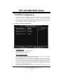
CHAPTER 1: INTRODUCTION
1.1 BEFORE YOU START
Tha nk you for choo sing our pro duct. Be fore you start installing the
mo the rboa rd, plea se make sure you fo llo w the instructions be low:
Prepare a dry and stable working environment with
s ufficie nt ligh ting .
Always disconnect the computer from power outlet
be fo re ope ra tion.
Befo re you take the mo the rboa rd ou t f rom a n ti-s ta tic
bag, ground yourself properly by touching any safely
grounde d appliance, o r use gro unded wrist strap to
remove the static charge.
Avo id tou ch ing the com pone nts o n mo the rboa rd o r the
rear side of the board unless necessary. Hold the board
on the edge, do not try to bend or flex the boa rd.
Do not lea ve any unfastene d sma ll pa rts inside the
case after installation. Loose parts will cause short
circuits which may damage the equipment.
Keep the computer from dangerous area, such as heat
source, humid air and wate r.
1.2 PACKAGE CHECKLIST
FDD Cable X 1
HDD Cable X 1
Use r’s Ma nual X 1
Fully Setup Driver CD X 1
Rear I/O Panel for ATX Case X 1
Se ria l ATA Cab le X 1 ( op tiona l)
USB 2.0 Cable X1 (optional)
S/PDIF Cable X 1 (optional)
Se ria l ATA Po we r Switch Cab le X 1 (op tiona l)

Motherboard Manual
2
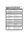
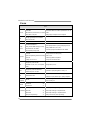
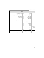
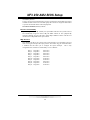
1.3 MOTHERBOARD FEATURES
SPEC
CPU
Socket AM2
AMD Athlon 64 / Athlon 64 FX / Althlon
64X2 / Sempron processors
AMD 64 Arc hitecture enables 32 and 64 bit computing
Supports Hyper Transport and Cool=n=Quiet
FSB Support HyperTransport Supports up to 800 MHz Bandwidth
Chipset nVIDIA NF3 250
Super I/O
ITE 8716F
Provides the most commonl
y
us e d l e
g
ac
y
Super I/O functionalit y.
Low Pin Count Interface
Environment Control initiatives,
H/W Monitor
Fan Speed Controller
ITE's "Smart Guardian" function
Main
Memory
DIMM Slots x 2
Eac h DIMM s upports 256/512MB & 1GB
DDR2
Max Memory Capicity 2GB
Dual Channel Mode DDR2 memory module
Supports DDR2 533 / 667 / 800
Registered DIMM and ECC DIMM is not supported
IDE
Integrated IDE Controller
Ultra DMA 33
/
66
/
100
/
133 Bus Maste
r
Mode
supports PIO Mode 0~4,
SA TA
Integrated Serial ATA Controller
Data transfer rates up to 1.5 Gb/s.
SATA Version 1.0 specification compliant.
LAN Realtek 8201CL PHY
10 / 100 Mb/s Auto-Negotiation
Half / Full duplex capability
Sound ALC 655
6 channels audio output
AC 97 Version 2. 3
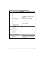
PCI slot x5 Supports PCI cards
Slots
AGP slot x1 Supports AGP cards
Floppy connector x1 Each connector supports 2 Floppy drives
IDE Connector x2 Each connector supports 2 IDE device
SATA Connector x2 Each connector supports 1 SATA devices
Front Panel Connector x1 Supports front panel facilities
Front Audio Connector x1 Supports front panel audio function
On Board
Connector
CD-in Connec tor x1 Supports CD audio-in function

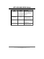
NF3 250 AM2
3
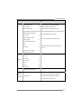
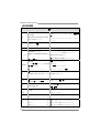
SPEC
S/PDIF out connector x1 Supports digital audio out function
CPU Fan header x1 CPU Fan power supply (with Smart Fan function)
System Fan header x1 System Fan Power supply
Chassis open header (optional) x1 For chassis intruder detection function
CMOS clear header x1 Restore CMOS data to factory default
USB connector x2 Each connector supports 2 front panel USB ports
Power Connector (20pin) x1 Connects to Power supply
Power Connector (4pin) x1 Connects to Power s upply
Back Panel
I/O
PS/2 Keyboard x1
PS/2 Mouse x1
Printer Port x1
S e ri a l Port x 1
LAN port x1
USB Port x4
Audio Jack x3
Connects to PS/2 Keyboard
Connects to PS/2 Mouse
Provide Parallel connection
Provide RS-232 Serial c onnection
Connects to RJ-45 ethernet cable
Connects to USB devices
Provide Audio-In/Out and microphone connection
Board Siz e 204 x 297 (mm) ATX Form Factor
OS Support Windows 2K / XP
Biostar Reserves the right to add or remove support for
any OS With or without notice.
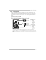
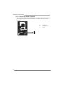
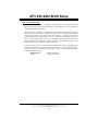
1.4 REAR PANEL CONNECTORS
Line In/
Surround
Line Out
Mi c I n /
Base/Center
PS/2
Mouse
PS/2
Keyboard
COM1 COM3
(optional)
USBX2USBX2
LAN
Printer Port

Motherboard Manual
4
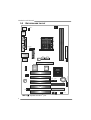
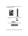
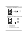
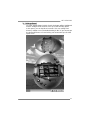
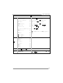
1.5 MOTHERBOARD LAYOUT
IDE1
IDE2
JATXPWR2
JAT XP W R 1
Super I/O
nVIDIA
nForce 3
250
JAUD IO 1
JCDIN1
J SPDIF_ OU T
(optional)
SATA2 SATA1
J USBV 3
JUSB1
JSFAN 1
JCMOS1
JC I 1
(Optional)
JC FAN1
DIMMA1
DIMMB1
JUSB2
LAN
Codec
J USBV 1
JK BM S1
JUSB3
JPR NT 1
J
C
O
M
1
JUSBLAN1
JAUDIO
J
C
O
M
3
PCI1
PCI2
PCI3
PCI4
PCI5
BIOS
AGP 1
Socket A M2
FDD1
JSFAN 2
(Optional)
BAT1
JI R1(o pt io na l )
JPANE L1
No te: represents the 1■
st
pin.

NF3 250 AM2
5
CHAPTER 2: HARDWARE INSTALLATION
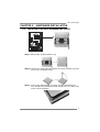
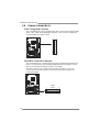
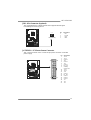
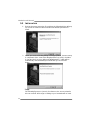
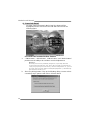
2.1 INSTALLING CENTRAL PROCESSING UNIT (CPU)
Step 1: Remove the socket protection cap.
Step 2: Pull the lever toward direction A from the socket and then raise the
lever up to a 90-degree angle.
Step 3: Look for the white triangle on socket, and the gold triangle on
CPU should point towards this white triangle. The CPU will fit only
in the correct orientation.

Motherboard Manual
6
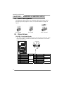
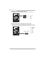
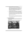
Step 4: Hold the CPU down firmly, and then close the lever toward direct
B to complete the installation.
Step 5: Put the CPU Fan on the CPU and buckle it. Connect the CPU
FAN power cable to the JCFAN1. This completes the installation.

NF3 250 AM2
7
2.2 FAN HEADERS
These fan headers support cooling-fans built in the computer. The fan
cable and connector may be different according to the fan manufacturer.
Connect the fan cable to the connector while matching the black wire to
pin#1.
JCFAN1: CPU Fan Header
JSFAN1/ JSFAN2(Optional): System Fan Header
JCFAN1
Pin Assignment
1 Ground
2 +12V
3
FAN RPM
rate sense
4 Smart Fan
Control
JSFAN1/JSFAN2
Pin Assignment
1 Ground
2 +12V
14
1
3
JCFAN1
JSFAN1
JSFA N2
(O ption al)
3
FAN RPM
rate sense
Note:
The JCFAN1、JSFAN1/JSFAN2 support 4-pi n and 3-pin head connector. When
connecting with wires onto connectors, please note that the red wire is the positive and
should be connected to pi n#2, and the bl ack wire is Ground and should be connected to
GND.

Motherboard Manual
8
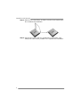
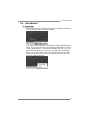
2.3 INSTALLING SYSTEM MEMORY
A. Memory Modules
DIMMA
1
DIMMB
1
1. Unlock a DIMM slot by pressing the retaining clips outward. Align a
DIMM on the slot such that the notch on the DIMM matches the
break on the Slot.
2. Insert the DIMM vertically and firmly into the slot until the retaining
chip snap back in place and the DIMM is properly seated.

NF3 250 AM2
9
B. Memory Capacity
DIMM Socket
Location
DDR Module
To t a l Me m o r y
Size
DIMMA1 256MB/512MB/1024MB
DIMMB1 256MB/512MB/1024MB
Max is 2GB.
E. Dual Channel Memory installation
To trigger the Dual Channel function of the motherboard, the memory module
must meet the following requirements:
Install memory module of the same density in pairs, shown in the following
table.
Duual Channel Status
DIMMA1
DIMMB1
Disabled O X
Disabled X O
Enabled O O
(O means memory installed, X means memory not installed.)
The DRAM bus width of the memory module must be the same (x8 or
x16)

Motherboard Manual
10
2.4 CONNECTORS AND SLOTS
FDD1: Floppy Disk Connector
The motherboard provides a standard floppy disk connector that supports 360K,
720K, 1.2M, 1.44M and 2.88M floppy disk types. This connector supports the
provided floppy drive ribbon cables.
1
33
2
34
IDE1/IDE2: Hard Disk Connectors
The motherboard has a 32-bit Enhanced PCI IDE Controller that provides PIO
Mode 0~4, Bus Master, and Ultra DMA 33/66/100/133 functionality. It has two
HDD connectors IDE1 (primary) and IDE2 (secondary).
The IDE connectors can connect a master and a slave drive, so you can
connect up to four hard disk drives. The first hard drive should always be
connected to IDE1.
2
1
39
40
IDE1
IDE2

NF3 250 AM2
11
PCI1~PCI5: Peripheral Component Interconnect Slots
This motherboard is equipped with 5 standard PCI slots. PCI stands for
Peripheral Component Interconnect, and it is a bus standard for expansion
cards. This PCI slot is designated as 32 bits.
PCI1
PCI2
PCI3
PCI4
PCI5
AGP1: Accelerated Graphics Port Slot
Your monitor will attach directly to that video card. This motherboard supports
video cards for PCI slots, but it is also equipped with an Accelerated Graphics
Port (AGP). An AGP card will take advantage of AGP technology for improved
video efficiency and performance, especially with 3D graphics.
AGP1

Motherboard Manual
12
CHAPTER 3: HEADERS & JUMPERS SETUP
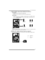
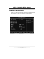
3.1 HOW TO SET UP JUMPERS
The illustration shows how to set up jumpers. When the jumper cap is
placed on pins, the jumper is “close”, if not, that means the jumper is
“open”.
Pin opened Pin closed Pin1-2 closed
3.2 DETAIL SET T ING S
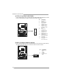
JPANEL1: Front Panel Header
This 16-pin connector includes Power-on, Reset, HDD LED, Power LED, Sleep
button and speaker connection. It allows user to connect the PC case’s front
panel switch functions.
1
8
16
SLP
PWR_LED
On/Off
RST
HLED
SPK
++
+
9
-
-
Pin Assignment Function Pin Assignment Functio n
1 +5V 9 Sleep control
2 N/A 10 Ground
Sleep button
3 N/A 11 N/A N/A
4 Speaker
Speaker
Connector
12 Power LED (+)
5 HDD LED (+) 13 Power LED (+)
6 HDD LED (-)
Hard drive
LED
14 Power LED (-)
Power LED
7 Ground 15 Power button
8 Reset control
Reset button
16 Ground
Power-on button

NF3 250 AM2
13
JIR1: IrDA Connector (Optional)
The motherboard has a Infrared header that supports infrared signal
transmitting and receiving device.
Pin
Assignment
1 +5V
2 Ground
3 IRTX
4 IRRX
IR (optional)
12
34
JATXPWR1: ATX Power Source Conne ctor
This connector allows user to connect 20-pin power connector on the ATX
power supply.
Pin Assignment
1 +3.3V
2 +3.3V
3 Ground
4 +5V
5 Ground
6 +5V
7 Ground
8 PW_OK
9 Standby
Voltage +5V
10 +12V
11 +3.3V
12 -12V
13 Ground
14 PS_ON
15 Ground
16 Ground
17 Ground
18 -5V
19 +5V
1
10
11
20
20 +5V

Motherboard Manual
14
JATXPWR2: ATX Power Source Conne ctor
By connecting this connector, it will provide +12V to CPU power circuit.
Pin
Assignment
1 +12V
2 +12V
3 Ground
1
23
4
4 Ground
JUSB1/JUSB2: Headers for USB 2.0 Ports at Front Panel
This header allows user to connect additional USB cable on the PC front panel,
and also can be connected with internal USB devices, like USB card reader.
Pin
Assignment
1 +5V (fused)
2 +5V (fused)
3 USB-
4 USB-
5 USB+
6 USB+
7 Ground
8 Ground
9 Key
19
210
JUSB2 JUSB1
10 NC

NF3 250 AM2
15
JUSBV1/JUSBV3: Powe r Source Headers for USB Ports
Pin 1-2 Close:
JUSBV1: +5V for USB ports at JUSBLAN1.
JUSBV3: +5V for USB ports at front panel (JUSB1/JUSB2).
Pin 2-3 Close:
JUSBV1: USB ports at JUSBLAN1 are powered by +5V standby voltage.
JUSBV3: USB ports at front panel (JUSB1/JUSB2) are powered by +5V
standby voltage.
1
3
1
3
Pin 1-2 close
1
3
3
JUSBV3
JUSBV1
1
1
3
1
3
Pin 2-3 close
Note:
In order to support this function “Power-On system via USB device,” “JUSBV1/ JUSBV3”
jumper cap should be placed on Pin 2-3 indi viduall y.
JSPDIF_OUT1: Digital Audio-out Connector (Optional)
This connector allows user to connect the PCI bracket SPDIF output header.
Pin
Assignment
1 +5V
2 SPDIF_OUT
13
3 Ground

Motherboard Manual
16
JAUDIO1: Front Panel Audio Header
This header allows user to connect the front audio output cable with the PC front
panel. It will disable the output on back panel audio connectors.
Pin Assignment
1 Mic in/center
2 Ground
3 Mic power/Bass
4 Audio power
5 Right line out/
Speaker out Right
6 Right line out/
Speaker out Right
7 Reserved
8 Key
9 Left line out/
Speaker out Left
10 Left line out/
Speaker out Left
11 Right line in/
Rear speaker Right
12 Right line in/
Rear speaker Right
13 Left line in/
Rear speaker Left
14
2
13
1
14 Left line in/
Rear speaker Left
JCDIN1: CD-ROM Audio-in Connector
This connector allows user to connect the audio source from the variaty devices,
like CD-ROM, DVD-ROM, PCI sound card, PCI TV turner card etc..
Pin
Assignment
1 Left Channel
Input
2 Ground
3 Ground
14
4 Right Channel
Input

NF3 250 AM2
17
SATA1~SATA2: Serial ATA Connectors
The motherboard has a PCI to SATA Controller with 2 channels SATA interface,
it satisfies the SATA 1.0 spec and with transfer rate of 1.5Gb/s.
Pin
Assignment
1 Ground
2 TX+
3 TX-
4 Ground
5 RX-
6 RX+
147
SATA1
SATA2
7 Ground
JCMOS1: Clear CMOS Header
By placing the jumper on pin2-3, it allows user to restore the BIOS safe setting
and the CMOS data, please carefully follow the procedures to avoid damaging
the motherboard.
1
3
Pin 1-2 Close:
Normal Operation (default).
1
3
1
3
Pin 2-3 Close:
Clear CMOS data.
※ Clear CMOS Procedures:
1. Remove AC power line.
2. Set the jumper to “Pin 2-3 close”.
3. Wait for five seconds.
4. Set the jumper to “Pin 1-2 close”.
5. Power on the AC.
6. Reset your desired password or clear the CMOS data.

Motherboard Manual
18
JCI1: Chassis O pen Header (Optional)
This connector allows system to monitor PC case open status. If the signal has
been triggered, it will record to the CMOS and show the message on next
boot-up.
Pin
Assignment
1 Case open signal
1
2 Ground
Page is loading ...
Page is loading ...
Page is loading ...
Page is loading ...
Page is loading ...
Page is loading ...
Page is loading ...
Page is loading ...
Page is loading ...
Page is loading ...
Page is loading ...
Page is loading ...
Page is loading ...
Page is loading ...
Page is loading ...
Page is loading ...
Page is loading ...
Page is loading ...
Page is loading ...
Page is loading ...
Page is loading ...
Page is loading ...
Page is loading ...
Page is loading ...
Page is loading ...
Page is loading ...
Page is loading ...
Page is loading ...
Page is loading ...
Page is loading ...
Page is loading ...
Page is loading ...
Page is loading ...
Page is loading ...
Page is loading ...
Page is loading ...
Page is loading ...
Page is loading ...
Page is loading ...
Page is loading ...
Page is loading ...
Page is loading ...
Page is loading ...
Page is loading ...
Page is loading ...
Page is loading ...
Page is loading ...
Page is loading ...
Page is loading ...
Page is loading ...
Page is loading ...
Page is loading ...
Page is loading ...
Page is loading ...
Page is loading ...
Page is loading ...
Page is loading ...
Page is loading ...
Page is loading ...
Page is loading ...
Page is loading ...
Page is loading ...
Page is loading ...
Page is loading ...
Page is loading ...
Page is loading ...
-
 1
1
-
 2
2
-
 3
3
-
 4
4
-
 5
5
-
 6
6
-
 7
7
-
 8
8
-
 9
9
-
 10
10
-
 11
11
-
 12
12
-
 13
13
-
 14
14
-
 15
15
-
 16
16
-
 17
17
-
 18
18
-
 19
19
-
 20
20
-
 21
21
-
 22
22
-
 23
23
-
 24
24
-
 25
25
-
 26
26
-
 27
27
-
 28
28
-
 29
29
-
 30
30
-
 31
31
-
 32
32
-
 33
33
-
 34
34
-
 35
35
-
 36
36
-
 37
37
-
 38
38
-
 39
39
-
 40
40
-
 41
41
-
 42
42
-
 43
43
-
 44
44
-
 45
45
-
 46
46
-
 47
47
-
 48
48
-
 49
49
-
 50
50
-
 51
51
-
 52
52
-
 53
53
-
 54
54
-
 55
55
-
 56
56
-
 57
57
-
 58
58
-
 59
59
-
 60
60
-
 61
61
-
 62
62
-
 63
63
-
 64
64
-
 65
65
-
 66
66
-
 67
67
-
 68
68
-
 69
69
-
 70
70
-
 71
71
-
 72
72
-
 73
73
-
 74
74
-
 75
75
-
 76
76
-
 77
77
-
 78
78
-
 79
79
-
 80
80
-
 81
81
-
 82
82
-
 83
83
-
 84
84
-
 85
85
-
 86
86


Biostar NF3 Owner's manual
- Category
- Motherboards
- Type
- Owner's manual
- This manual is also suitable for
Ask a question and I''ll find the answer in the document
Finding information in a document is now easier with AI
Related papers
-
Biostar NF325-A9 Owner's manual
-
-
-
-
-
-
-
-
Biostar GF7050V-M7 SE User manual
-
Other documents
-
Dell 56193617 Datasheet
-
Mach P4MST-890 Setup Manual
-
Albatron K8X250GB PRO User manual
-
 Shuttle Computer Group SA76 User manual
-
 IWILL FB24624100 User manual
-
PC CHIPS A13G (V1.0) User guide
-
EVGA 512-A8-N403-KR Datasheet
-
-
-
Foxconn A6VMX-K User manual

