Page is loading ...

CX700
10” x 22” METAL LATHE
with DIGITAL READOUT
User Manual

2
TABLE OF CONTENTS
General Safety Instructions................................................................................................. 3
Specific Safety Instructions................................................................................................. 4
Features.............................................................................................................................. 5
Physical Features................................................................................................................ 6
Set-Up................................................................................................................................. 7
Un-Packing & Inventory ...................................................................................................... 7
Proper Grounding................................................................................................................ 8
Chuck.................................................................................................................................. 9
Steady Rest......................................................................................................................... 9
Follow Rest .........................................................................................................................10
Lathe Bed............................................................................................................................10
Headstock...........................................................................................................................10
Gearbox ..............................................................................................................................11
Headstock Controls.............................................................................................................11
Apron...................................................................................................................................12
Saddle.................................................................................................................................12
Carriage Controls................................................................................................................12
Lead Screw.........................................................................................................................13
Tailstock..............................................................................................................................14
Tailstock Controls................................................................................................................14
Test Run..............................................................................................................................15
Speed Change....................................................................................................................16
Longitudinal Turning with Auto-Feed ..................................................................................17
Manual Longitudinal Turning...............................................................................................17
Facing and Recesses..........................................................................................................17
Turning Between Centers ...................................................................................................18
Thread Cutting ....................................................................................................................18
Change Gears Replacement...............................................................................................19
Gibs Adjustment..................................................................................................................19
Chuck Run-Out ...................................................................................................................20
Headstock and Tailstock Alignment....................................................................................21
Main Spindle Bearings........................................................................................................22
Lubrication...........................................................................................................................22
Maintenance........................................................................................................................24
Optional Stand ....................................................................................................................25
Troubleshooting ..................................................................................................................26
Parts Diagram and Parts List.......................................................................................27 –48
Warranty..............................................................................................................................49

3
GENERAL SAFETY INSTRUCTIONS
FOR MACHINES
Extreme caution should be used when operating all power tools. Know your power
tool, be familiar with its operation, read through the user manual and practice safe
usage procedures at all times.
ALWAYS read and understand the
user manual before operating the
machine.
CONNECT your machine ONLY to the
matched and specific power source.
ALWAYS wear safety glasses
respirators, hearing protection and
safety shoes, when operating your
machine.
DO NOT wear loose clothing or
jewelry when operating your machine.
A SAFE ENVIRONMENT is
important. Keep the area free of dust,
dirt and other debris in the immediate
vicinity of your machine.
BE ALERT! DO NOT use prescription
or other drugs that may affect your
ability or judgment to safely operate
your machine.
DISCONNECT the power source when
changing drill bits, hollow chisels,
router bits, shaper heads, blades,
knives or making other adjustments or
repairs.
NEVER leave a tool unattended while it
is in operation.
NEVER reach over the machine when
the tool is in operation.
ALWAYS keep blades, knives and bits
sharpened and properly aligned.
ALL OPERATIONS MUST BE
performed with the guards in place to
ensure safety.
ALWAYS use push sticks and feather
boards to safely feed your work through
the machine and clamp the work-piece
(when necessary) to prevent the work-
piece from any unexpected movement.
ALWAYS make sure that any tools used
for adjustments are removed before
operating the machine.
ALWAYS keep the bystanders safely
away while the machine is in operation.
NEVER attempt to remove jammed
cutoff pieces until the saw blade has
come to a full stop.

4
This machine is designed and
intended for use by properly trained
and experienced personnel only. If
you are not familiar with the proper
use of lathes, do not use this machine
until proper training and knowledge
has been obtained.
Keep guards in place. Safety guards
must be kept in place and in working
order all the times to ensure safety.
Keep children and visitors away. All
children and visitors should be kept at
a safe distance from the work area.
Wear proper apparel. Loose clothing,
gloves, neckties, rings, bracelets, or
other jewelry may get caught in
moving parts. Non-slip footwear is
recommended. Wear protective hair
covering to contain long hair. Do not
wear any type of gloves.
Always use safety glasses. For the
safety of your eyes, safety glasses
should be used while operating the
lathe.
Do not use the lathe in dangerous
environments. Do no expose the
machine to rain. Do not use the
machine in wet locations.
Check for damaged parts. Check for
proper alignment of moving parts,
broken parts, and any other conditions
that may effect the tools operation.
Remove adjusting keys and
wrenches. Remove all the tools used
for adjustment before turning the
machine on.
Be careful. Do not put your hand close
to the cutter while the machine is
running.
Never leave the lathe unattended while
it is running.
Do not over-reach. Keep proper footing
and balance at all times.
Maintain tools with care. Keep tools
sharp and clean for best and safest
performance. Follow instructions given
in the manual for lubrication and
replacing accessories.
Turn the power OFF. Before making
any adjustments, make sure the switch
is in the “OFF” position and the cord is
un-plugged from the power outlet.
Make sure you have read and
understood all the safety instructions in
the manual and you are familiar with
your metal lathe, before operating it. If
you fail to do so, serious injury could
occur.
CX700 - METAL LATHE
SPECIFIC SAFETY INSTRUCTIONS
WARNING
The safety instructions given above can not be complete because the environment in
every shop is different. Always consider safety first as it applies to your individual
working conditions.

5
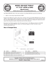
MODEL CX700 – 10” x 22” METAL LATHE WITH VARIABLE SPEED
As part of the growing line of Craftex metalworking equipment, we are proud to offer the CX700 a 10” x
28” Metal Lathe with Digital Readout. The Craftex name guarantees Craft Excellence. By following the
instructions and procedures laid out in this user manual, you will receive years of excellent service and
satisfaction. The CX700 is a professional tool and like all power tools, proper care and safety
procedures should be adhered to.
Motor....................................................1-HP, 0.75 KW, DC90 V, 8-Amps
Swing Over Bed...................................10” (250mm)
Swing Over Cross Slide.......................5-1/2” (140mm)
Distance Between Centers ..................21-3/4” (550mm)
Width of Bed ........................................5-5/16” (135mm)
Hole Through Spindle..........................7/8” (21mm)
Spindle Nose Taper.............................MT3
Number of Spindle Speeds..................Variable
Range of Spindle Speeds....................A = 100 – 1100 RPM, B=200 – 2200 RPM
Number of Metric Threads ...................15
Range of Metric Threads .....................0.35mm – 3.5mm
Number of Imperial Threads ................27
Range of Imperial Threads ..................8 – 56 T.P.I
Tool Post Type.....................................4-Way
Max Compound Slide Travel................3” (80mm)
Max Cross Slide Travel........................4” (100mm)
Maximum Carriage Travel....................22” (550mm)
Tailstock Spindle Travel.......................2-1/2” (65mm)
Taper in Tailstock Spindle....................MT2
Overall Dimension of the lathe.............Length 47” x Width 26” x Height 22”
Weight..................................................165 Kgs (364 lbs)
Warranty ..............................................3-Years
CX700 – METAL LATHE
FEATURES

6
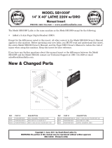
CX700 - METAL LATHE
PHYSICAL FEATURES
A. Variable Speed Switch
B. Spindle RPM Digital Readout
C. Headstock
D. ON/OFF, Emergency Switch
E. Forward/Reverse Switch
F. 3-Jaw Chuck
G. Four Way Tool Post
H. Tail Stock Quill Lock Lever
I. Tail Stock
J. Tailstock Lock Lever
K. Tail Stock Hand Wheel
L. Tailstock Adjustment Screw
M. Lathe Bed
N. Lead Screw
O. Chip Tray
P. Thread Dial Indicator
Q. Half Nut Lever
R. Feed Selector Lever
S. Carriage Hand Wheel
T. Cross Slide Hand Wheel
U. Gearbox Oil Fill Plug
V. Feed/Thread Selector Knob
W. Oil Sight Glass
X. Feed Rate Selector Knob
Y. Threading/Feeding Table
Z. Feed Direction Lever

7
SETUP
Before setting up your machine you should
read and understand the instructions given
in this manual.
The unpainted surfaces of this lathe are
coated with a rust preventive waxy oil and
you will want to remove this before starting
assembly. Use a solvent cleaner that will
not damage painted surfaces.
When setting up your machine, you will
want to find an ideal spot where your metal
lathe will most likely be positioned most of
the time.
Figure-1 CX700 Foot print
UNPACKING
To ensure safe transportation this machine
is properly packaged and shipped
completely in crates. When unpacking,
carefully inspect the crates and ensure that
nothing has been damaged during transit.
Open the crates and check that the
machine and the parts are in good
condition.
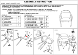
LIST OF CONTENTS QTY
A. Face Plate........................................ 1
B. Change Gears ................................ 17
C. 4-Jaw Chuck.................................... 1
D. 3-Jaw Chuck.................................... 1
E. Steady Rest ..................................... 1
F. Follow Rest...................................... 1
G. External Jaws for 3-Jaw Chuck........ 3
H. Dead Center MT3, MT2................... 2
I. Oil Gun............................................. 1
J. Toolbox............................................ 1
K. 4-Way Tool Post .............................. 1
L. Wrenches (8-10, 12-14)................... 2
M. Hex Wrenches (2, 3, 4, 5, 6)............ 5
N. Chuck Keys...................................... 1
O. Screw Drivers (Flat & Cross Head).. 2
P. Lathe (Not Shown)........................... 1
Figure-2 Inventory
While doing inventory, if you can not find
any part, check if the part is already
installed on the machine. Some of the parts
come assembled with the machine because
of shipping purposes.
WARNING
CX700 is a very heavy machine, do not
over-exert yourself. Use fork truck or
other mechanical devices for safe
moving method

8
PROPER GROUNDING
Grounding provides a path of least
resistance for electric current to reduce the
risk of electric shock.
CX700 is equipped with a DC 90-V single
phase motor.
To prevent electrical hazards, have a
qualified electrician ensure that the line is
properly wired.
This lathe is for use on a normal 110 volt
circuit. Make sure that the appliance is
connected to an outlet having the same
configuration as the plug. If an adaptor
plug is used, it must be attached to the
metal screw of the receptacle.
Figure-3 110-Volts Outlet for CX700
It is strongly recommended not to use
extension cords with your CX700. Always
try to position your machine close to the
power source so that you do not need to
use extension cords.
Incase if you really find it necessary to use
an extension cord, make sure the extension
cord does not exceed 50-feet in length and
the cord is 12-gauge to prevent motor
damage.
Your CX700 should be wired with a plug
having 3-prongs to fit a 3 prong grounding
receptacle as shown in figure-3.
Do not remove the grounding prong to fit it
into a 2-pronged outlet. Always check with
a qualified electrician if you are in doubt.
WARNING
Improper connection of the equipment-
grounding conductor can result in a risk
of electric shock. Check with a qualified
electrician if you are in doubt as to
whether the outlet is properly grounded.

9
CHUCK
CX700 comes equiped with a 125mm, 3-
jaw chuck, a 125mm, 4-jaw chuck and a
220mm faceplate.
The 3-jaw chuck is a scroll type chuck,
meaning that all three jaws move in union
when adjusted while the 4-jaw chuck
features four independent jaws. The 4-jaw
chuck is used to clamp square or unevenly-
shaped work-pieces.
The chucks feature three hex nut and three
set screws for mounting as shown in figure-
4.
Figure-4 Chuck mounting screws and nuts
When removing the chuck, loosen the hex
nuts, turn the washer counter-clockwise
and pull out the chuck. See figure-4.
STEADY REST
The steady rest supports long, small
diameter stock that otherwise could not be
turned. The steady rest can also replace
the tailstock to allow for cutting tool acces
at the outboard end of your work-piece.
To mount the steady rest:
Secure the steady rest to the lathe bed from
below with a locking plate.
A single cap screw, along with a nut and
washer hold the steady rest in place as
shown in figure-5.
Figure-5 Steady rest
TO SET-UP THE STEADY REST:
Make sure the switch is in the OFF position
and the cord is disconnected from the
power source.
Loosen the hex nuts shown in figure-5.
Loosen knurled screw and open the sliding
fingers until the steady rest can be moved
with its finger around the work-piece.
Secure the steady rest in position. See
figure-5.
Tighten the knurled screw so that the
fingers are snug but not tight against the
work-piece. Tighten three nuts shown in
figure-5 and lubricate the sliding points with
machine oil.

10
The sliding fingers of the steady rest shown
in figure-5 should receive periodic
lubrication when used, to prevent
premature wear.
FOLLOW REST
The follow rest is mounted on the saddle
with two cap screws shown in figure-6 and
it follows the movement of the turning tool.
Only two sliding fingers are required. The
place of the third finger is taken by turning
tool. The follow rest is used for turning
operations on long slender work-pieces. It
prevents flexing of the work-piece under
pressure from the turning tool.
Set the fingers snug to the work-piece and
make sure not to over tighten. Lubricate the
fingers during operation to prevent
premature wear.
Figure-6 Follow rest installed
LATHE BED
The lathe bed is made of high quality iron.
The lathe bed features high cheeks with
strong cross ribs ensuring low vibration and
rigidity. It integrates the headstock and
drive unit, for attaching the carriage and
leads crews. The two precision ground V-
sideways are re-enforced by heat
hardening and grinding to guide the
carriage and the tailstock accurately. The
main motor is mounted to the rear of the left
side of the bed.
Figure-7 Lathe bed
HEADSTOCK
Made from high quality, cast iron for low
vibration, the headstock is bolted to the bed
with four screws. The headstock houses the
main spindle with two precision taper roller
bearings and the drive unit.
The main spindle transmits the torque
during the turning process and it also holds
the work-piece and clamping devices.
Figure-8 Headstock

11
GEARBOX
The gearbox is located on the left side of
the lathe and is mounted on the bed. It is
used to select the feeds for straight turning
as well as for thread cutting. In order to
achieve certain thread pitches, it is
necessary to replace the change gears.
The torque of the work spindle is
transmitted to the feed gears and thus to
the lead screw.
Figure-9 Gearbox
HEADSTOCK CONTROLS
EMERGENCY ON/OFF BUTTON: The
On/Off button allows to start and stop the
machine.
Figure-10 ON/OFF switch
FORWARD / REVERSE SWITCH: After the
machine is switched ON, turn the switch to
“F” position for counter-clockwise spindle
rotation (forward).
Turn the switch to “R” position for clockwise
spindle rotation (Reverse).
Turning the switch to “0” position the
spindle remains idle.
Figure-11 Forward / Reverse switch
FEED RATE SELECTOR KNOB: Use the
feed rate selector knob to set the desired
feed or thread rates. See figure-12.
FEED THREAD SELECTOR KNOB: For
thread selecting, shift the knob to the left
and for feed selecting, shift the knob to the
right. See figure-12.
FEED DIRECTION LEVER: Pull the knob
on the feed direction lever to disengage and
position the lever up or down to change the
rotating direction of the carriage Release
the nut to lock the lever in position.
Putting the lever in the top position, moves
the carriage to the left along the bed and

12
moves the top slide towards the work-piece,
while the spindle is turning counter-
clockwise.
Putting the lever in the bottom position,
moves the carriage to the right along the
bed and moves the top slide away from the
work-piece, while the spindle is turning
counter-clockwise.
Putting the lever in the middle position,
disengages the gears and the feed screw
does not turn, while the spindle is turning
counter-clockwise.
VARIABLE SPEED CONTROL KNOB:
Turn the knob clockwise to increase the
spindle speed and counter-clockwise to
decrease the spindle speed. The possible
speed range is dependent on the position of
the drive belt. See figure-12.
Figure-12 Headstock controls
APRON
The apron is mounted to the saddle and to
the front side of the bed and it houses the
half nut with an engaging lever for
activating the automatic feed. The half nut
gibs can be adjusted from the outside.
SADDLE
The saddle is made from high quality cast
iron and all sliding parts are smoothly
ground to fit the V on the bed without play.
Figure-13 Saddle and apron
CARRIAGE CONTROLS
The carriage allows the cutting tool to move
along the length of the lathe bed .The cross
slide allows the cutting tool to travel
perpendicular to the bed. The carriage
features a top slide which allows linear
movement of the cutting tool at any preset
angle .This section will review the individual
controls on the carriage and provide
descriptions of their uses.
LONGITUDINAL TRAVEL HAND WHEEL:
Turning the longitudinal hand wheel, moves
the carriage left or right along the bed .The
control is helpful when setting up the
machine for turning, when manual
movement is desired during turning
operations. See figure-14.
CROSS SLIDE HAND WHEEL: Turning
the cross slide hand wheel, moves the
cross slide towards or away from the work-
piece. The graduated scale can be adjusted

13
using the same method as the longitudinal
scale. See figure-14.
TOP SLIDE HAND WHEEL: The top slide
hand wheel controls the position of the
cutting tool relative to the work-piece .The
top slide is adjustable for angle as well as
longitudinal travel. It can be adjusted a full
360°, if needed. The graduated scale is
adjustable using the same method as the
other hand wheels. See figure-14.
TOOL POST: A four-way tool post is
supplied with the CX700. Cutting tools can
be attached and removed by tightening or
loosening the clamping bolt. See figure-14.
Figure-14 Carriage controls
FEED SELECTOR LEVER: Moving this
lever upward engages the automation
longitudinal feed. Moving this lever down
engages the automation transverse feed.
See figure-15.
HALF NUT LEVER: This lever engages
and disengages the half nut on the lead
screw. The lever is only engaged while
turning threads in stock. A lockout device
feature in the lever mechanism engages
when the feed selector is used.
THREADING DIAL INDICATOR: This
indicator tells you when to engage the half
nut for threading process. See figure-15.
Figure-15 Carriage controls
LEAD SCREW
The lead screw is mounted on the front of
the machine bed. It is connected to the gear
box at the left for automatic feed and is
supported by bearing on both ends.
Figure-16 Lead screw
WARNING
DO NOT simultaneously engage the
feed selector lever and the half nut lever.
Doing so will damage the lathe.

14
TAILSTOCK
The tailstock slides on a V-way and can be
clamped at any location. The tailstock has a
heavy duty spindle and the spindle can be
clamped at any location with a clamping
lever. The spindle is moved with a hand
wheel at the end of the tailstock.
Figure-17 Tailstock
Make sure to install the securing screw at
the end of the lathe as shown in figure-10 in
order to prevent the tailstock from falling off
the lathe bed.
Figure-18 Installing the securing screw on
the lathe bed
TAILSTOCK CONTROLS
TAILSTOCK HAND WHEEL: Turning the
hand wheel advances or retracts the quill in
the tailstock. The graduated scale on the
hand wheel is adjustable. See figure-19.
QUILL LOCK LEVER: This lock lever locks
the quill in position when tightened. See
figure-19.
TAILSTOCK LOCK LEVER: Turn this lock
lever up to lock and down to unlock the
tailstock in position on the lathe bed. See
figure-19.
ADJUSTMENT SCREW: This set screw is
used to align the tailstock with the
headstock. See page-21 for details on
center alignment.
Figure-19 Tailstock controls

15
TEST RUN
Once you have assembled your lathe
completely, it is then time for a test run to
make sure that the lathe works properly and
is ready for operation.
Remove all the tools used for assembling
the machine and make sure all the guards
are in place.
To ensure the carriage controls do not
move unexpectedly when the lathe is
started, rotate the feed direction selector
knob so that the arrow is pointing to the
middle (neutral) position. See figure-20.
Figure-20 Feed direction selector knob
Connect the cord to the power outlet and
turn the machine ON.
While test running the machine, check the
following:
The Emergency Stop & ON/OFF buttons
are working properly.
The chuck and jaws are properly secured
and working properly.
While the machine is running, turn the
variable speed control knob clockwise to
make sure it is working properly.
Let the machine run for 10 minutes at the
Low Speed.
During the test run if there is any unusual
noise coming from the lathe or it vibrates
excessively, turn OFF the power switch
immediately and disconnect from the power
source Investigate if you can find out the
problem with your machine. See page-26
for troubleshooting.
If the machine is running smoothly, proceed
to the next step.
Change the belt for High Speed and let the
machine run for another 10 minutes. See
page-16 for details on speed change.
Turn the machine OFF and turn the
Forward/Reverse switch to “R” position.
Turn the machine back ON and make sure
the spindle is rotating clockwise (reverse).
WARNING
Before starting the lathe, make sure that
you have read and understood the
manual and you are familiar with the
functions and safety features on this
machine. Failure to do so may cause
serious personal injury.
WARNING
Do not make any adjustments while the
machine is running. Failure to follow this
warning can cause serious personal
injuries to the operator and damage to the
machine.

16
SPEED CHANGE
The rotating speed of the headstock is
controlled by the positioning of the belts on
the pulleys. These are accessed by
removing the cover on the end of the
headstock.
Refer to the plate on the headstock to
determine which belt combinations produce
what speeds. The speed settings available
on the machine are 100 – 1100 RPM and
200 - 2200 RPM.
TO CHANGE THE SPINDLE SPEED:
Unscrew the two fastening knobs shown in
figure-21 and remove the protective cover.
Figure-21 Removing the cover
Loosen the four nuts and screws shown in
figure-22 and move the motor mounting
pulley to release the tension on the belt.
Once the belt tension is released, reposition
the belt on the pulleys grooves for high or
low spindle speed.
Figure-22 Screws and nuts securing the
motor mounting plate
Position the belt on the pulleys for high and
low speed according to figure-23.
The low spindle speed is 100 – 1100 RPM
while the high spindle speed is 200 – 2200
RPM.
Figure-23 Belt position on the pulleys
Once the belt is on the right grooves, move
the motor pulley back to its position to
tension the belt.
Re-tighten the screws and nuts removed
and re-install the protective cover.
IMPORTANT
We suggest selecting the low speed. It
provides stronger torque while operation.

17
LONGITUDINAL TURNING
WITH AUTO-FEED
Set the feed direction lever and feed rate
selector knob shown in figure-24 to select
the feed direction and feed speed.
Figure-24 Feed rate selector knob, feed
direction lever and chart
Use the chart on the lath for selecting the
feed speed or the thread pitch. Select the
proper gear set if the required feed or
thread pitch can not be obtained with the
installed gear set. Automatic feed is
accomplished by moving the auto feed
selector lever, up. See figure-25.
Figure-25 Auto feed selector lever
MANUAL LONGITUDINAL
TURNING
In this turning operation, the tool feeds
parallel to the axis of rotation (longitudinal)
of the work-piece. Manual feed is
accomplished by turning the carriage hand
wheel on the lathe apron or the top slide.
The cross feed for the depth of cut is
achieved using the cross slide. See figure-
26.
Figure-26 Straight turning
FACING AND RECESSES
In the facing operation, the tool feeds
perpendicular to the axis of rotation of the
work-piece. The feed is made manually with
the cross slide hand wheel. The depth of
cut is made with the top slide. See figure-
27.
Figure-27 Facing & dressing

18
TURNING BETWEEN
CENTERS
For turning between centers, it is necessary
to remove the chuck from the spindle. Fit
the MT2 center into the reducing sleeve
(not provided) and fit the reducing sleeve
into the spindle taper. If you are using the
MT3 center (provided), you can simply fit
the center into the spindle taper.
Mount the work-piece fitted with the driver
dog between the centers. The driver is
driven by a catch or face plate. See figure-
28.
Figure-28 Turning between centers
THREAD CUTTING
Several different threads can be cut using
the proper combination of gears and
settings.
IMPERIAL THREAD: When cutting inch
threads, the half nut and threading dial are
used to thread in a conventional manner.
The threading and feeding chart on the
headstock specifies at which point a thread
can be entered using the threading dial.
METRIC THREAD: The only difference in
metric thread cutting is that the half nut
must remain engaged during the entire
threading process. The thread dial can not
be utilized.
Figure-29 Half nut and threading dial
Set the machine up for the desired thread
pitch.
Start the machine and engage the half nut.
When the tool reaches the end of the cut,
stop the machine by turning the motor off
and at the same time back the tool out off
the work-piece so that it clears the thread.
Do not disengage the half nut lever.
Reverse the motor direction allowing the
cutting tool to traverse back to the starting
point.
Repeat these steps until you have obtained
results.
IMPORTANT
Always use a small amount of grease on
the tailstock center to prevent center tip
from over heating.

19
LEFT AND RIGHT THREAD CUTTING:
The left and right thread cutting is done
using the feed direction selector knob.
Turning the feed direction selector knob
counter-clockwise, cuts left thread while
turning it clockwise, cuts right thread.
.
CHANGE GEARS
REPLACEMENT
To replace the change gears:
Make sure the switch is in the OFF position
and the cord is unplugged from the power
outlet.
Unscrew the two fastening knobs and
remove the protective cover to access the
change gears.
Unscrew the bolt from the lead screw and
the square bolts shown in figure-30 from
the quadrant bolts in order to remove the
change gears.
Figure-30 Change gears replacement
Select the proper gear set according to your
requirements from the chart given on the
head stock and install it onto the quadrant
using nuts removed.
Re-install the protective cover.
GIBS ADJUSTMENT
There are two main gib screws adjustment
for the machine; the cross slide gib screws
and the top slide gib screws.
CROSS SLIDE GIB SCREWS
ADJUSTMENT
The adjustment gibs are located on the left
side of the cross slide. To adjust gib, loosen
the nuts holding the gibs. Tighten the gibs
until excess movement is eliminated and
retighten the nuts. See figure-31.
Figure-31 Cross slide adjustment gib
screws
WARNING
Make sure the switch is in the OFF
p
osition and the cord is disconnected
from the power source before making
any adjustments. Failure to do so can
result serious personal injury.
IMPORTANT
We suggest selecting the low speed. It
provides stronger torque while operation.

20
TOP SLIDE GIBS ADJUSTMENT
Locate the adjustment gibs on the side of
the top slide as shown in figure-32. Loosen
the nuts holding the gibs and then tighten
the gibs until excess movement is
eliminated. Once all the gibs are tightened
properly, retighten the nuts.
Figure-32 Top slide adjustment gibs screws
CHUCK RUN-OUT
If your lathe requires a higher level of
accuracy, you may find it necessary to true-
up the chuck to ensure minimal run-out.
To check and correct the chuck run-out:
Mount a piece of bar stock in the chuck.
The stock should protrude approximately
50mm.
Use a dial indicator and measure the run-
out at the end of the bar. In most cases, the
amount of run-out will not exceed 0.12mm
over 50mm which should be accurate
enough for most applications. If the run-out
on the chuck is excessive (e.g. greater than
0.15mm), the excess run-out should be
eliminated.
Start by removing the chuck.
Remove the bolts, securing the back plate
to the chuck. Tap along the edge of the
mounting shoulder until the chuck and back
plate are free of each other and thread back
plate onto the spindle.
Remove about 0.12mm of material from the
surface that the chuck mounts to. Be
careful not to remove any material from the
diameter of the shoulder. See figure-33.
Figure-33 Turning the back plate
Install the chuck onto the back plate and
check the run-out. If the run-out is not within
an acceptable range, it may be necessary
to turn a new shoulder on the back plate.
Before turning a new shoulder, measure the
diameter of the recess in the back of the
chuck accurately.
Remove approximately one half of the
thickness of the shoulder (approximately
1.5mm). Remove the same thickness off
the face of the mounting surface.
Figure-34 Turning new shoulder on back
/