Miller 20090200000001 Owner's manual

Category
Welding System
Type
Owner's manual
Description
Powered Air-Purifying Respirator
OM-235 936 Rev. K 2014−05
Visit our website at
www.MillerWelds.com
File: Accessory
Powered Air-Purifying Respirator
(PAPR)
To help us serve you better, go to www.MillerWelds.Com/Register
TABLE OF CONTENTS
SECTION 1 − SAFETY PRECAUTIONS − READ BEFORE USING 1.................................
1-1. Symbol Usage 1.......................................................................
1-2. Arc Welding Hazards 1.................................................................
1-3. Lens Shade Selection Table 2............................................................
1-4. Proposition 65 Warnings 3...............................................................
1-5. Principal Safety Standards 3.............................................................
1-6. NIOSH Approval Information 4...........................................................
SECTION 2 − POWERED AIR-PURIFYING RESPIRATOR (PAPR) 5.................................
2-1. Respirator Specifications 5..............................................................
2-2. Charging The Battery 6.................................................................
2-3. Installing The Battery 6.................................................................
2-4. Installing The Air Filter 7................................................................
2-5. Attaching The Breathing Tube − Welding Helmet Head Assembly 8.............................
2-6. Attaching The Breathing Tube − Hard Hat Head Assembly 9..................................
2-7. Operating The Controls 10................................................................
2-8. Testing Air Flow 11......................................................................
2-9. Testing Air Flow Alarm 12................................................................
2-10. Installing Shoulder Strap 12...............................................................
2-11. Checking The Respirator Before Use 13....................................................
2-12. Putting On The Respirator 14.............................................................
2-13. Maintenance And Storage 14.............................................................
2-14. Respirator Troubleshooting 15............................................................
SECTION 3 − WELDING HELMET HEAD ASSEMBLY 16...........................................
3-1. Specifications 16........................................................................
3-2. Helmet Configurations 17.................................................................
3-3. Helmet Controls 18......................................................................
3-4. Auto On/Off Button And Grind Mode / Low Battery Light 18....................................
3-5. Mode Control Button 19..................................................................
3-6. Variable Shade Control 20................................................................
3-7. Lens Delay Control 20...................................................................
3-8. Sensitivity Control 21....................................................................
3-9. Typical Lens Adjustment Procedure 22.....................................................
3-10. Info Control Button 23....................................................................
3-11. Arc Time Control 23.....................................................................
3-12. Clock Control 24........................................................................
3-13. Timer Control 24........................................................................
3-14. Alarm Control 25........................................................................
3-15. Adjusting Headgear 25...................................................................
3-16. Replacing Lens Covers 26................................................................
3-17. Replacing Grinding Shield On Titanium 9400i Helmet 27.......................................
3-18. Replacing The Battery 27................................................................
3-19. Installing Optional Magnifying Lens 28......................................................
3-20. Maintenance 28.........................................................................
3-21. Troubleshooting 29......................................................................
SECTION 4 − HARD HAT HEAD ASSEMBLY 30...................................................
4-1. Specifications 30........................................................................
4-2. Attaching Welding Helmet To Hard Hat 30...................................................
4-3. Adjusting Hard Hat Headgear 31..........................................................
4-4. Replacing Hard Hat Lens 32..............................................................
SECTION 5 − PARTS LIST 34...................................................................
WARRANTY
OM-235 936 Page 1
SECTION 1 − SAFETY PRECAUTIONS − READ BEFORE USING
PAPR 2013-04
Protect yourself and others from injury — read, follow, and save these important safety precautions and operating instructions.
1-1. Symbol Usage
DANGER! − Indicates a hazardous situation which, if
not avoided, will result in death or serious injury. The
possible hazards are shown in the adjoining symbols
or explained in the text.
Indicates a hazardous situation which, if not avoided,
could result in death or serious injury. The possible
hazards are shown in the adjoining symbols or ex-
plained in the text.
NOTICE − Indicates statements not related to personal injury.
. Indicates special instructions.
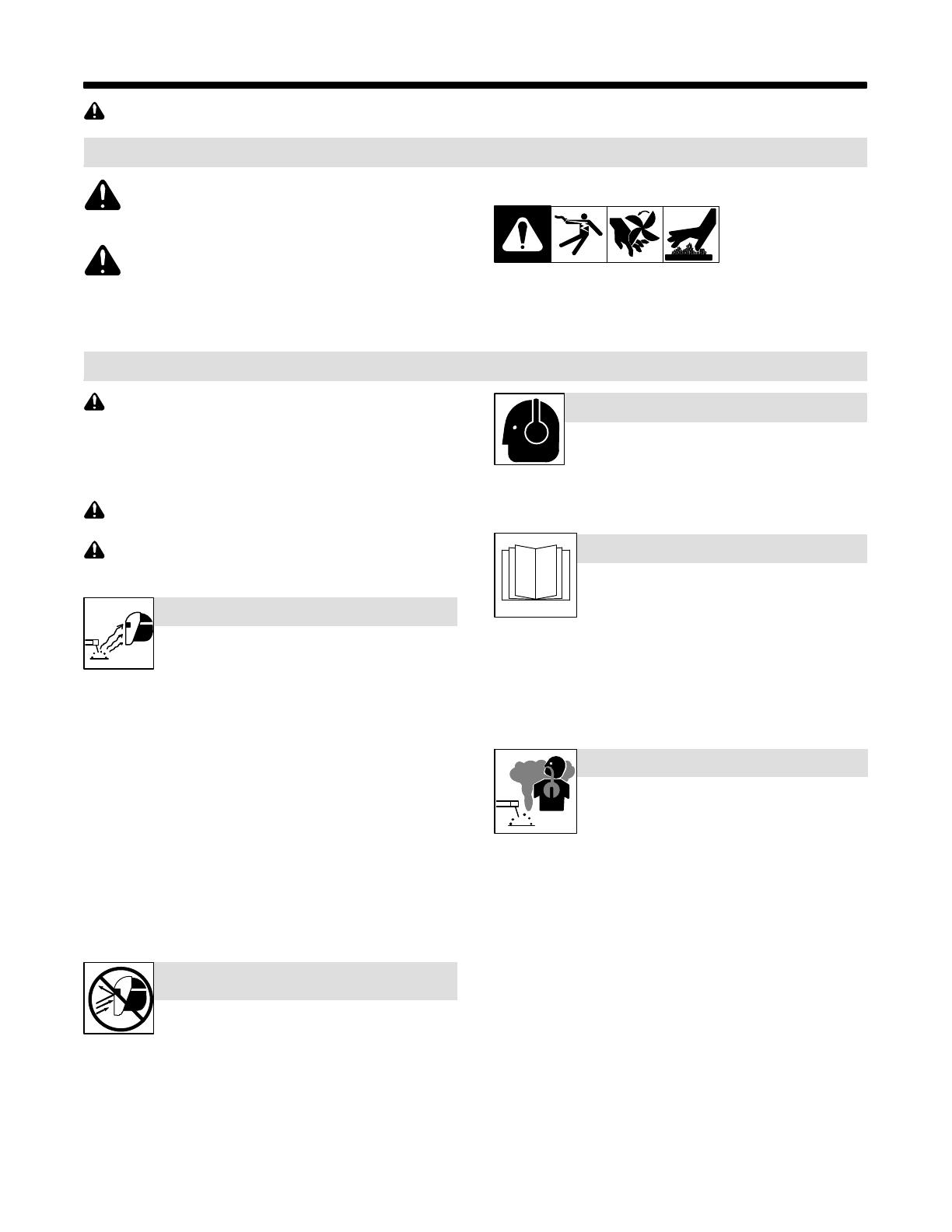
This group of symbols means Warning! Watch Out! ELECTRIC
SHOCK, MOVING PARTS, and HOT PARTS hazards. Consult sym-
bols and related instructions below for necessary actions to avoid the
hazards.
1-2. Arc Welding Hazards
The symbols shown below are used throughout this manual
to call attention to and identify possible hazards. When you
see the symbol, watch out, and follow the related instructions
to avoid the hazard. The safety information given below is
only a summary of the more complete safety information
found in the Safety Standards listed in Section 1-5. Read and
follow all Safety Standards.
Only qualified persons should install, operate, maintain, and
repair this unit.
During operation, keep everybody, especially children, away.
Arc rays from the welding process produce intense
visible and invisible (ultraviolet and infrared) rays tha
t
can burn eyes and skin. Sparks fly off from the weld
.
D Wear a welding helmet fitted with a proper shade of filter to
protect your face and eyes when welding or watching (see ANS
I
Z49.1 and Z87.1 listed in Safety Standards). Refer to Lens
Shade Selection table in Section 1-3.
D Wear approved safety glasses with side shields under your
helmet.
D Use protective screens or barriers to protect others from flash,
glare, and sparks; warn others not to watch the arc.
D Wear protective clothing made from durable, flame-resistant
material (leather, heavy cotton, and wool) and foot protection.
Before welding, adjust the auto-darkening lens sensitivity setting
to meet the application.
Stop welding immediately if the auto-darkening lens does not
darken when the arc is struck. See the Owner’s Manual for
more information.
ARC RAYS can burn eyes and skin.
WELDING HELMETS do not provide
unlimited eye, ear and face protection
.
Arc rays from the welding process produce intense vis
-
ible and invisible (ultraviolet and infrared) rays that ca
n
burn eyes and skin. Sparks fly off from the weld.
D Use impact resistant safety spectacles or goggles and ear
protection at all times when using this welding helmet.
D Do not use this helmet while working with or around explosives
or corrosive liquids.
D Do not weld in the overhead position while using this helmet.
D Inspect the auto-lens frequently. Immediately replace any
scratched, cracked, or pitted cover lenses or auto-lenses.
NOISE can damage hearing.
Noise from some processes or equipment can dam-
age hearing.
D Wear approved ear protection if noise level is high.
READ INSTRUCTIONS.
D Read and follow all labels and the Owner’s
Manual carefully before installing, operating, or
servicing unit. Read the safety information at
the beginning of the manual and in each
section.
D Use only genuine replacement parts from the manufacturer.
D Perform maintenance and service according to the Owners
Manuals, industry standards, and national, state, and local
codes.
FUMES AND GASES can be hazardous
.
Welding produces fumes and gases. Breathing
these fumes and gases can be hazardous to you
r
health.
D Keep your head out of the fumes. Do not breathe the fumes.
D If inside, ventilate the area and/or use local forced ventilation at
the arc to remove welding fumes and gases.
D If ventilation is poor, wear an approved air-supplied respirator.
D Read and understand the Material Safety Data Sheets (MSDSs)
and the manufacturer’s instructions for metals, consumables,
coatings, cleaners, and degreasers.
D Work in a confined space only if it is well ventilated, or while
wearing an air-supplied respirator. Always have a trained watch-
person nearby. Welding fumes and gases can displace air and
lower the oxygen level causing injury or death. Be sure the
breathing air is safe.
D Do not weld in locations near degreasing, cleaning, or spraying
operations. The heat and rays of the arc can react with vapors to
form highly toxic and irritating gases.
D Do not weld on coated metals, such as galvanized, lead, or
cadmium plated steel, unless the coating is removed from the
weld area, the area is well ventilated, and while wearing an air-
supplied respirator. The coatings and any metals containing
these elements can give off toxic fumes if welded.
OM-235 936 Page 2
RESPIRATOR (PAPR) MISUSE can b
e
hazardous.
Welding produces fumes and gases. Breathing thes
e
fumes and gases can be hazardous to your health.
D Read and follow these instructions and the safety labels carefully.
The powered air purifying respirator (PAPR) helps protect the user
from specific airborne contaminants but must be used correctly to
be fully effective. Have an industrial hygienist test the air in your
facility to ensure the PAPR provides adequate protection from con-
taminants in your environment. If you have questions about the
respirator, see equipment NIOSH label and consult your Safety Di-
rector and a certified Industrial Hygienist.
D Follow all applicable ANSI, OSHA, CSA, and other regulatory
guidelines pertaining to the use of respirators.
D Do not use the powered air purifying respirator where there is dan-
ger of fire or explosion.
D Do not use the powered air purifying respirator in windy conditions
or negative pressure inside the hood may draw in contaminants
from the outside air.
D Do not use the powered air purifying respirator without a properly
installed spark guard. Without the spark guard, welding sparks
may ignite the filter or damage the filters and allow unfiltered air into
the helmet.
D The powered air purifying respirator does not supply oxygen. Use
the respirator only in atmospheres for which it is NIOSH approved.
Do not use the respirator where oxygen levels are 19.5% or lower,
where contaminant levels are unknown or are immediately dan-
gerous to life or health (IDLH), or where the contaminant levels
exceed the respirator specifications.
D Do not enter a hazardous area until you are sure the respirator
equipment is correctly assembled, working properly, and properly
worn.
D Before each use, inspect the respirator equipment for damage and
verify it operates properly. Before using the respirator, test air flow
to verify it is providing an adequate volume of air.
D Do not use the powered air purifying respirator without all filter
components or with the blower turned off or hazardous levels of ox-
ygen and carbon dioxide may accumulate in the helmet.
D Always wear the powered air purifying respirator when entering a
contaminated area. Do not remove the respirator until outside the
contaminated area.
D Dangerous contaminants may not smell or be visible. Leave the
area immediately if you notice the following:
Breathing becomes difficult....
You experience dizziness, impaired vision, or eye, nose, or ...
mouth irritation.
The powered air purifying respirator alarm sounds....
The equipment is damaged....
Air flow decreases or stops....
If you think the equipment is not supplying adequate...
protection.
Do not remove the equipment until you are in a safe area.
D Do not repair, modify, or disassemble the powered air purifying res-
pirator or use with parts or accessories not supplied by the
manufacturer. Use only those components that are part of the
NIOSH-approved assembly.
D Replace damaged or clogged filters. Do not wash or reuse filters.
Do not clean filters by tapping or with compressed air or filter ele-
ments may be damaged. Dispose of used filter elements
according to local, state, and federal requirements.
D The powered air purifying respirator must be used with the helmet,
hood, and filters recommended by the manufacturer to provide a
NIOSH-approved respirator system. See the NIOSH label for in-
formation on the required equipment.
D Do not use the powered air purifying respirator belt and shoulder
straps as a safety harness.
D The powered air purifying respirator contains electrical parts which
have not been evaluated as an ignition source in flammable or ex-
plosive atmospheres by MSHA/NIOSH.
1-3. Lens Shade Selection Table
Process
Electrode Size
in. (mm)
Arc Current
in
Amperes
Minimum
Protective
Shade No.
Suggested
Shade No.
(Comfort)*
Shielded Metal Arc Welding (SMAW) Less than 3/32 (2.4)
3/32−5/32 (2.4−4.0)
5/32−1/4 (4.0−6.4)
More than 1/4 (6.4)
Less than 60
60−160
160−250
250−550
7
8
10
11
−−
10
12
14
Gas Metal
Arc Welding (GMAW)
Flux Cored
Arc Welding (FCAW)
Less than 60
60−160
160−250
250−500
7
10
10
10
−−
11
12
14
Gas Tungsten Arc Welding (TIG) Less than 50
50−150
150−500
8
8
10
10
12
14
Air Carbon
Arc Cutting (CAC-A)
Light
Heavy
Less than 500
500−1000
10
11
12
14
Plasma Arc
Cutting (PAC)
Less than 20
20−40
40−60
60−80
80−300
300−400
400−800
4
5
6
8
8
9
10
4
5
6
8
9
12
14
Plasma Arc Welding (PAW) Less than 20
20−100
100−400
400−800
6
8
10
11
6−8
10
12
14
Reference: ANSI Z49.1:2005
* Start with a shade that is too dark to see the weld zone. Then, go to a lighter shade which gives a sufficient view of the weld zone without going below
the minimum.
OM-235 936 Page 3
1-4. Proposition 65 Warnings
Welding or cutting equipment produces fumes or gases
which contain chemicals known to the State of California to
cause birth defects and, in some cases, cancer. (California
Health & Safety Code Section 25249.5 et seq.)
This product contains chemicals, including lead, known to
the state of California to cause cancer, birth defects, or other
reproductive harm. Wash hands after use.
1-5. Principal Safety Standards
Safety in Welding, Cutting, and Allied Processes, ANSI Standard Z49.1,
is available as a free download from the American Welding Society at
http://www.aws.org or purchased from Global Engineering Documents
(phone: 1-877-413-5184, website: www.global.ihs.com).
Safe Practice For Occupational And Educational Eye And Face Protec-
tion, ANSI Standard Z87.1, from American National Standards Institute,
25 West 43rd Street, New York, NY 10036 (phone: 212-642-4900, web-
site: www.ansi.org).
OM-235 936 Page 4
1-6. NIOSH Approval Information
POWERED AIR PURIFYING RESPIRATOR
OM-235 936 Page 5
SECTION 2 − POWERED AIR-PURIFYING RESPIRATOR
(PAPR)
This equipment helps protect the user from certain contaminants. All users must read and understand these instructions and be
trained in the proper use of this equipment before using. Use this equipment according to all applicable health and safety standards.
If you have questions about the type of respiratory equipment required, consult your safety director and an Industrial Hygienist.
Do not enter a hazardous area until you are sure the respirator equipment is correctly assembled, working properly, and properly worn.
. See Section 3 for information on the auto-darkening helmet assembly. See Section 4 for information on the hard hat option.
The powered air-purifying respirator (PAPR) filters contaminated air and blows it into the welding helmet hood through a flexible breathing tube. The
respirator system generates a positive air pressure to help prevent contaminants from entering the hood. The system must include and/or be used
with the equipment listed below:
D Helmet or helmet/hardhat option with auto-darkening lens, hood, and headgear system
D Breathing Tube
D Blower assembly with filtration system (spark guard, foam prefilter, HEPA filter), and low battery and low air flow alarms
D Belt assembly
D Air flow indicator
D Battery charger
The respirator equipment operates at temperatures from 23° to 131° F and provides air flow of 6+ CFM (low speed) to 7.06 CFM (high speed) under
normal conditions. Battery life is reduced when the unit is used in a dirty environment. If the system air flow decreases to an unsafe level, an alarm
will sound, the blower vibrates, and the Danger light will flash to warn the user to immediately leave the contaminated area. Use the supplied air flow
indicator to determine if the unit is supplying adequate amounts of clean air.
2-1. Respirator Specifications
Size (Blower Assembly) 9-1/2 x 8-1/4 x 3 in. (241 x 210 x 76 mm)
Weight
(Blower Assembly, Filters, Belt, Shoulder Straps, and
Battery)
51.7 oz. (1466 g)
Standard Air Filter Filter Assembly Consisting Of A Spark Guard Screen, Foam Prefilter, And Partic-
ulate (HEPA) Filter − All Part Of The NIOSH-Approved PAPR.
Approved To Filter Particulate Down To 0.3 Micrometers In Size.
Air Flow Low Speed: 6+ CFM (170+ LPM) minimum
High Speed: 7.06 CFM (200 LPM)
Operating Temperature 23° to 131° F (−5° to 55° C)
Storage Temperature 14° to 176° F (−10° to 80° C)
Battery Type Rechargeable Lithium
Battery Charging Time About Three hours
Battery Life 500 Charges − Run Time Dependent On Air Flow Rate And Filter Load.
Belt size 28 to 55 in. (711 to 1397 mm)
Notes
Work like a Pro!
Pros weld and cut
safely. Read the
safety rules at
the beginning
of this manual.
POWERED AIR PURIFYING RESPIRATOR
OM-235 936 Page 6
2-2. Charging The Battery
! Charge battery only with sup-
plied charger in an open, well−
ventilated location.
! Do not allow battery to get wet.
Do not attempt to open the bat-
tery case.
! Keep battery away from fire or
heat.
! Charge battery before first use
or if battery has not been used
for five days.
. Dispose of battery at a designated
collection facility.
. Battery charging stops when bat-
tery is fully charged.
1 Battery Terminal
2 120 Volt AC Battery Charger
3 120 Volt AC Receptacle
Remove battery from blower assembly.
Connect charger cord to battery termi-
nal. Connect charger to 120 volt AC re-
ceptacle.
The charger red light goes on when bat-
tery is being charged. When fully
charged, the charger green light goes
on. Charging normally takes about four
hours.
. If red light flashes during charging,
stop charging for 30 minutes then
charge battery an additional 20
minutes (green light will be on).
805 099
1
2
3
2-3. Installing The Battery
1 Battery
2 Battery Unlock Button
Slide battery into blower body until
battery snaps into position.
To remove battery, push battery un-
lock button down and pull battery
from blower assembly.
2
1
Ref. 805 068
POWERED AIR PURIFYING RESPIRATOR
OM-235 936 Page 7
2-4. Installing The Air Filter
! Do not use the respirator
without the spark guard
screen, foam prefilter, and
particulate (HEPA) filter
installed.
! Replace damaged or dirty air
filters. Do not wash filters,
clean with compressed air,
or reuse dirty air filters.
. Dispose of used filters at a des-
ignated collection facility.
1 Particulate (HEPA) Filter
2 Foam Prefilter
3 Spark Guard Screen
4 Cover
Install the screen, prefilter, and par-
ticulate filter in cover exactly as
shown.
Install the filter assembly by sliding
the tabs on the cover into the brack-
et on the blower body; push down
on the filter until it “clicks” into posi-
tion.
Ref. 805 096
3
1
2
4
POWERED AIR PURIFYING RESPIRATOR
OM-235 936 Page 8
2-5. Attaching The Breathing Tube Welding Helmet Head Assembly
Ref. 805 068 / 805 098
! Be sure breathing tube is
properly installed or contami-
nated air may enter the hel-
met.
Connecting Breathing Tube To
Helmets Equipped With Tab Con-
nector
1 Locking Tab
Push breathing tube connector (rect-
angular end) into helmet air inlet until
breathing tube locks in position.
(Locking tab should be on outside of
helmet air inlet.)
. Do not insert breathing tube
locking tab into helmet inlet.
Locking tab should be on out-
side of helmet air inlet.
Connecting Breathing Tube To
Blower
Align pins on breathing tube connec-
tor (blower end) with channels in
blower receptacle. Insert tube con-
nector into blower receptacle until
snug and then turn connector 1/8
turn clockwise.
1
Tab Connector
Titanium 9400 Helmet
and
Titanium 9400i Helmet
POWERED AIR PURIFYING RESPIRATOR
OM-235 936 Page 9
2-6. Attaching The Breathing Tube − Hard Hat Head Assembly
! Be sure breathing tube is
properly installed or contami-
nated air may enter the hard
hat.
Connecting Breathing Tube To
Hard Hat
1 Locking Tabs
Align breathing tube connector lock-
ing tabs with channels in hard hat air
inlet. Push breathing tube connector
into helmet air inlet. Rotate breathing
tube clockwise until breathing tube
locks in position.
Connecting Breathing Tube To
Blower
Align pins on breathing tube connec-
tor (blower end) with channels in
blower receptacle. Insert breathing
tube connector into blower recep-
tacle until snug and then turn con-
nector 1/8 turn clockwise.
POWERED AIR PURIFYING RESPIRATOR
OM-235 936 Page 10
2-7. Operating The Controls
! Leave the contaminated area
immediately if the Danger
light goes On, the alarm
sounds, or the blower vi-
brates. Do not remove the
equipment until you are in a
safe area.
1 On Button
2 Off Button
3 Danger Indicator
4 Low Speed Indicator
5 High Speed Indicator
6 Battery Level Indicator
. Indicator lights are always red.
To Start: Press On button for 1−2
seconds until the blower starts. The
Danger indicator lights and then
goes out, the alarm sounds, and the
blower vibrates momentarily.
The blower always starts at the low
speed. Press the On button to
switch between High and Low
speeds.
To Stop: Press Off button for 2 − 3
seconds until the audible alarm and
blower stop.
The Danger indicator light goes on,
the alarm sounds, and the blower vi-
brates if battery power is low or air
flow is reduced due to a dirty filter,
blocked breathing tube, or other
problem. See Section 2-14, Trou-
bleshooting.
The Battery Level indicator lights
show the power remaining in the
battery. When all three lights are on
the battery is fully charged.
3 4
1
2
56
Ref 805 068
POWERED AIR PURIFYING RESPIRATOR
OM-235 936 Page 11
2-8. Testing Air Flow
! Always test air flow before
using the respirator. Also
check air flow each month if
respirator is not used regu-
larly.
1 Flowmeter
2 Breathing Tube Connector
(Hood)
Disconnect breathing tube from
hood. Insert flowmeter into breath-
ing tube. Be sure breathing tube is
straight and untwisted. Hold flow-
meter straight up and start blower.
Air flow is adequate if flowmeter ball
moves above MIN mark. Do not
use respirator if flowmeter reads
MIN or below. If air flow is low,
check battery and filter elements
and recheck air flow.
805 098 / 805 101
2
1
1
2
Hard Hat Head Assemblies
Titanium 9400 Helmet
Titanium 9400i Helmet
Head Assemblies
POWERED AIR PURIFYING RESPIRATOR
OM-235 936 Page 12
2-9. Testing Air Flow Alarm
! Always test air flow alarm
before using the respirator.
Also check air flow alarm
each month if respirator is
not used regularly.
Disconnect breathing tube from
hood. Start blower and block air
flow by placing your hand over the
end of the breathing tube. Continue
blocking air flow until alarm sounds
and the blower vibrates (about 15 to
20 seconds).
If alarm does not sound and the
blower does not vibrate, check bat-
tery and filter element.
805 101
2-10. Installing Shoulder Strap
1 Shoulder Strap
2 Snap
3 Link
Connect snaps on shoulder straps
to links on belt.
1
2
3
805 068
POWERED AIR PURIFYING RESPIRATOR
OM-235 936 Page 13
2-11. Checking The Respirator Before Use
Before using the respirator,
check the following items:
1 Air Filter Assembly
Verify the air filter is suitable for
the application and is NIOSH-ap-
proved. Also be sure the filter is
undamaged, properly as-
sembled, and securely con-
nected to the blower assembly.
2 Breathing Tube
Be sure the tube is undamaged
and properly connected to the
blower assembly and hood.
3 Battery
Verify the battery is fully charged
and securely connected to the
blower assembly.
4 Air Flow (Not Shown)
Test air flow according to Section
2-8.
5 Air flow Alarm
Turn on blower assembly and
check for audible, visual, and vi-
bratory alarms (see Sections 2-7
and 2-9). See Troubleshooting
section if alarms go on at any oth-
er time (Section 2-14).
6 Hood
Inspect the hood and replace if
damaged. See Troubleshooting
(Section 2-14) if air is not being
supplied to hood.
805 068
2
3
5
6
1
POWERED AIR PURIFYING RESPIRATOR
OM-235 936 Page 14
2-12. Putting On The Respirator
! Do not enter a hazardous area
until you are sure the respira-
tor equipment is correctly as-
sembled, working properly,
and properly worn.
! Leave the contaminated area
immediately if the Danger
light goes On, the alarm
sounds, or the blower vi-
brates. Do not remove the
equipment until you are in a
safe area.
. See Parts List in Section 5 for op-
tional belt extension.
Place blower assembly against lower
back with breathing tube extending
upwards. Slide straps over shoulders
and fasten belt around waist. Adjust
straps and belt so unit rests comfort-
ably against lower back.
Put on head assembly. Adjust head
assembly to fit snugly on head. Tight-
en hood drawstring (if equipped) to
establish a tight seal around head.
805 187
2-13. Maintenance And Storage
Replace damaged or dirty air filters. Do not wash filters, clean with compressed air, or reuse dirty air filters.
Never use solvents or abrasive cleaning solutions to clean the respirator. Keep water and other fluids out of blower assembly.
. Maintain accurate records of filter replacement and respirator maintenance.
For best performance clean the equipment after each use. Use a soft cloth dampened with a mild soap and water solution to wipe all external surfaces
clean. Allow to air dry.
Product usage, workplace contamination levels, and other factors affect the life of the filter elements. Replace filter elements if air flow is reduced due
to a dirty filter (see Section 2-4) and according to the filter change schedule established by your Safety Director and an Industrial Hygienist.
Inspect breathing tube and replace if damaged or if inside of tube is dirty.
If the respirator will not be used for an extended period, remove the filter and battery and store them in a clean, dry, cool place free of solvent-based
vapors.
POWERED AIR PURIFYING RESPIRATOR
OM-235 936 Page 15
2-14. Respirator Troubleshooting
Trouble Remedy
Blower does not supply air to hood. Press On button.
Dead battery; recharge battery (see Section 2-2).
Verify battery is properly connected to blower body.
Remove blockage from blower outlet and breathing tube.
Blower cannot be turned Off. Press Off button for two to three seconds.
Blower runs for short time even though
battery is fully charged.
Be sure battery is properly connected to battery charger.
Replace battery.
Replace charger.
Battery warning light is On and alarm
sounds.
Continue wearing the respirator and leave the contaminated area immediately. Charge or replace
the battery. The blower will operate for about 20 minutes after the warning light goes on.
Have Safety Director and an Industrial Hygienist determine if you are using the proper equipment
for the work environment.
Battery run time is too short. Replace battery.
Check air filter and replace if necessary (see Sections 2-4 and 2-8). A clogged air filter element
reduces battery life.
Danger light is On, alarm sounds or
blower vibrates.
Continue wearing the respirator and leave the contaminated area immediately. Check blower air
flow (see Sections 2-4 and 2-8).
Remove blockage from blower outlet and/or breathing tube. If alarm sounds or blower vibrates con-
tinuously, contact a Factory Authorized Service Agent.
Remove packaging from air filter.
Have Safety Director and an Industrial Hygienist determine if you are using the proper equipment
for the work environment.
Air supplied to hood smells and tastes
unusual; eyes and throat irritation.
Continue wearing the respirator and leave the contaminated area immediately. Check contamination
level of filter, and replace filter if necessary.
Check breathing tube connections to blower and hood.
Verify spark guard, prefilter, and particulate (HEPA) filter are installed in blower assembly.
Have Safety Director and an Industrial Hygienist determine if you are using the proper equipment
for the work environment.
Blower supplies insufficient air to hood. Check breathing tube connections to blower and hood.
Remove blockage from blower outlet and/or breathing tube.
Check air filter and replace if necessary (see Sections 2-4 and 2-8). A clogged air filter element
reduces battery life.
WELDING HELMET HEAD ASSEMBLIES
OM-235 936 Page 16
SECTION 3 − WELDING HELMET HEAD ASSEMBLY
. See Section 2 for information on the powered air-purifying respirator (PAPR) assembly. See Section 4 for information on the hard hat head
assemblies.
3-1. Specifications
Specification Titanium 9400/9400i Welding Helmet
Viewing Field 3.81 x 2.62 in (97 x 60mm)
Reaction Time 0.0000500 sec (1/20,000)
Available Shades
All Shades Provide
Continuous
UV And IR
Protection.
Weld Mode
Darkened State: No. 8 − No. 13
Light State: No. 3
Cut Mode
Darkened State: No. 5 − No. 8
Light State: No. 3
Grind Mode
Light State: No. 3
X-Mode
Darkened State: No. 8 − No. 13
Light State: No. 3
Sensitivity Control Adjustable For Varying
Ambient Light And
Welding Arc
Delay Control Slows Lens Dark-To-Light State Between 0.1 And 1.0 Seconds
Automatic Power Off Shuts Lens Off 45 Minutes After Last Arc Is Struck
Low Battery Light Red Led Illuminates To Indicate 2−3 Days Remaining Battery Life
Power Supply CR2450 Lithium Batteries
(Miller Part No. 217 043)
Sensors Independent/Redundant (Four)
Operating
Temperature
14_F to 131_F / −10_C to +55_C
. When Stored In Extremely Cold Temperatures, Warm Helmet To Ambient Temperature Before Welding.
Storage
Temperature
−4_F to 158_F / −20_C to +70_C
. When Stored In Extremely Cold Temperatures, Warm Helmet To Ambient Temperature Before Welding.
Total Weight
(Helmet, Lens, Headgear, Head
Seal)
Titanium 9400:
28.5 oz (808 g)
Titanium 9400i:
33.1 oz (938 g)
Standards ANSI Z87.1+(2010) and DIN/CSA/TUV
Warranty Three Years From Date Of Purchase (Section 6)
WELDING HELMET HEAD ASSEMBLIES
OM-235 936 Page 17
3-2. Helmet Configurations
1 Titanium 9400 Helmet
The 9400 helmet features a lar-
ger fixed position, auto-darkeni-
ng lens than the 7300 series and
is also designed for standard
welding applications.
2 Titanium 9400 Helmet w/
Hard Hat Option
The 9400 helmet includes an
ANSI Z89.1 − 2009 Certified,
Type 1 − Class C or G approved
hard hat and extended length
hood.
3 Titanium 9400i Helmet
The 9400i helmet features a
flip-up auto-darkening lens and
a separate, clear grinding
shield. Flip the lens up when
grinding and performing other
non-welding work. Flip the lens
down when welding or cutting.
OTOS / Ref. 804 111
1
3
2
WELDING HELMET HEAD ASSEMBLIES
OM-235 936 Page 18
3-3. Helmet Controls
The lens turns on (darkens) auto-
matically when welding begins and
turns off when welding stops.
1 Auto On/Off Button
(See Section 3-4)
2 Grind Mode / Low Battery
Light (Section 3-4)
3 Mode Control Button
(Section 3-5)
4 Lens/Info Adjustment Buttons
(See Sections 3-6 Thru 3-8)
. Use adjustment buttons to
change shade, delay, and
sensitivity settings when lens is
in Mode function. Use adjust-
ment buttons to change arc
time, clock, timer, and alarm
settings when lens is in Info
function.
5 Info Control Button (See
Section 3-10)
6 External Grind Mode Button
(Section 3-5)
. The External Grind Mode but-
ton is not available on the 9400i
helmet.
. The lens assembly saves the
shade, sensitivity, and delay
settings.
1 34
5
26
3-4. Auto On/Off Button And Grind Mode / Low Battery Light
1
2
. The auto-darkening lens turns
on (darkens) automatically
when welding begins and
turns off when welding stops.
1 Auto On/Off Button
Press Auto On/Off button to check
if the lens is working properly and
to begin Mode and Info adjust-
ments.
When the On/Off button is
pressed, the lens should darken
and return to the clear state. Do
not use the helmet if the lens does
not function as described. (See
Section 3-21, Troubleshooting.)
2 Grind / Low Battery Light
The Grind / Low Battery light blinks
when the lens is in the Grind mode.
Light stays on when 2−3 days of
battery life remain.
If battery power is low, replace with
CR2450 lithium batteries (2 re-
quiredMiller Part No. 217 043).
See Section 3-18.
  • Page 1 1
  • Page 2 2
  • Page 3 3
  • Page 4 4
  • Page 5 5
  • Page 6 6
  • Page 7 7
  • Page 8 8
  • Page 9 9
  • Page 10 10
  • Page 11 11
  • Page 12 12
  • Page 13 13
  • Page 14 14
  • Page 15 15
  • Page 16 16
  • Page 17 17
  • Page 18 18
  • Page 19 19
  • Page 20 20
  • Page 21 21
  • Page 22 22
  • Page 23 23
  • Page 24 24
  • Page 25 25
  • Page 26 26
  • Page 27 27
  • Page 28 28
  • Page 29 29
  • Page 30 30
  • Page 31 31
  • Page 32 32
  • Page 33 33
  • Page 34 34
  • Page 35 35
  • Page 36 36
  • Page 37 37
  • Page 38 38
  • Page 39 39
  • Page 40 40
  • Page 41 41
  • Page 42 42
  • Page 43 43
  • Page 44 44

Miller 20090200000001 Owner's manual

Category
Welding System
Type
Owner's manual

Ask a question and I''ll find the answer in the document

Finding information in a document is now easier with AI