Page is loading ...

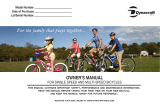
USER'S MANUAL
CAUTION
Read all precautions and instruc-
tions in this manual before using
this equipment. Keep this manual
for future reference.
Serial Number
Decal
Model No.
Serial No.
Write the model number and serial
number in the space above.
QUESTIONS?
As a manufacturer, we are com-
mitted to providing complete
customer satisfaction. If you
have questions, or if parts are
damaged, PLEASE DO NOT
CONTACT THE STORE; please
contact Customer Care.
Please note the product model
number and serial number
before contacting us:
CALL TOLL-FREE:
1-888-825-2588
Mon.–Fri. 6 a.m.–6 p.m. MST
Sat. 8 a.m.–4 p.m. MST
ON THE WEB:
www.nordictrackservice.com

2
TABLE OF CONTENTS
IMPORTANT PRECAUTIONS . . . . . . . . . . . . . . . . . . . . . . . . . . . . . . . . . . . . . . . . . . . . . . . . . . . . . . . . . . . . . . . .3
BEFORE YOU BEGIN . . . . . . . . . . . . . . . . . . . . . . . . . . . . . . . . . . . . . . . . . . . . . . . . . . . . . . . . . . . . . . . . . . . . . .5
ASSEMBLY . . . . . . . . . . . . . . . . . . . . . . . . . . . . . . . . . . . . . . . . . . . . . . . . . . . . . . . . . . . . . . . . . . . . . . . . . . . . . . .7
HOW TO OPERATE THE BICYCLE . . . . . . . . . . . . . . . . . . . . . . . . . . . . . . . . . . . . . . . . . . . . . . . . . . . . . . . . . . .14
PRE-CYCLING INSPECTION . . . . . . . . . . . . . . . . . . . . . . . . . . . . . . . . . . . . . . . . . . . . . . . . . . . . . . . . . . . . . . . .19
SAFE CYCLING TIPS . . . . . . . . . . . . . . . . . . . . . . . . . . . . . . . . . . . . . . . . . . . . . . . . . . . . . . . . . . . . . . . . . . . . . .20
MAINTENANCE AND TROUBLESHOOTING . . . . . . . . . . . . . . . . . . . . . . . . . . . . . . . . . . . . . . . . . . . . . . . . . . .21
ORDERING REPLACEMENT PARTS . . . . . . . . . . . . . . . . . . . . . . . . . . . . . . . . . . . . . . . . . . . . . . . . . .Back Cover
LIMITED WARRANTY . . . . . . . . . . . . . . . . . . . . . . . . . . . . . . . . . . . . . . . . . . . . . . . . . . . . . . . . . . . . . .Back Cover
NordicTrack is a registered trademark of ICON IP, Inc.

3
WARNING: To reduce the risk of serious injury, read all important precautions and
instructions in this manual and all warnings on your bicycle before using your bicycle. ICON
assumes no responsibility for personal injury or property damage sustained by or through the use
of this product.
IMPORTANT PRECAUTIONS
1. Before beginning any athletic activity, con-
sult your physician. This is especially impor-
tant for persons over the age of 35 or per-
sons with pre-existing health problems.
2. It is the responsibility of the owner to ensure
that all users of the bicycle are adequately
informed of all precautions.
3. Inspect and properly tighten all parts regu-
larly. Replace any worn parts immediately.
4. Your bicycle should not be used by persons
weighing more than 250 lbs. (113 kg).
5. It is your responsibility to ensure that your
bicycle is in safe working condition before
cycling (see PRE-CYCLING INSPECTION on
page 19).
6. Your bicycle has not been designed for com-
petition, stunt, or trick riding. Do not perform
these activities with your bicycle.
7. Never modify your bicycle frame or parts in
any way, including sanding, drilling, filing,
removing redundant retention devices, or
installing incompatible forks. An improperly
modified frame, fork, or component can
cause you to lose control of your bicycle
and fall.
8. Inflate your tires to the pressure marked on
the sidewalls of the tires. Use a manual hand
pump to inflate your tires; do not use com-
pressed air.
9. Do not cycle with your tires underinflated;
the sidewalls on the tire may crack and dam-
age the wheel rims.
10. Never carry a passenger on your bicycle.
11. Never hang bags, clothing, or other articles
on the handlebar of your bicycle; this will
affect your steering.
12. Always wear a protective helmet when
cycling.
13. Wear appropriate clothes when cycling; do
not wear loose clothes that could become
caught on your bicycle. Always wear shoes
with a textured tread for foot protection.
14. Hold the handlebar when mounting, dis-
mounting, or using your bicycle.
15. Keep your back straight while using your
bicycle; do not arch your back.
16. Squeeze both brake levers when slowing or
stopping your bicycle.

4
17. Keep your feet on the pedals when cycling.
Before bringing your bicycle to a complete
stop, remove one foot from a pedal and be
prepared to place your foot on the ground
when you stop the bicycle.
18. If you feel pain or dizziness while cycling,
stop immediately and cool down.
19. Use extra caution when cycling in wet condi-
tions. The braking performance of your bicy-
cle will be affected by water on braking sur-
faces and between the tires and the road
surface. Stopping distances will increase.
Take more time to slow or stop your bicycle
in wet conditions. Do not cycle in icy condi-
tions.
20. Use caution when cycling in the dark. If you
cycle in the dark, make sure that your bicy-
cle is equipped with a headlight, front and
rear reflectors, and wheel reflectors. Also,
make sure to wear light colored, reflective
clothes.
21. Servicing other than the procedures
described in this manual should be per-
formed by a qualified bicycle repair
specialist.
22. Use your bicycle only as described in this
manual.

5
Congratulations for selecting a new NordicTrack
®
UINTAH or WASATCH bicycle. Cycling is one of the
most effective exercises for increasing cardiovascular
fitness, building endurance, and toning the entire body.
For your benefit, read this manual carefully before
you use your bicycle. If you have questions after
reading this manual, please see the front cover of this
manual. To help us assist you, note the product model
number and serial number before contacting us. The
model number of the UINTAH bicycle is OMB06020.0;
the model number of the WASATCH bicycle is
OMB06003.0. The location of the serial number decal
is shown on the front cover of this manual.
Before reading further, please familiarize yourself with
the parts that are labeled in the photographs below.
BEFORE YOU BEGIN
Seat
OMB06020.0 Uintah
OMB06020.0 Uintah
Seat Clamp
Top Tube
Handlebar Stem
Kickstand
Pedal
Crank Arm
Seat Post
Fork
Disc Brake
Disc
Caliper Brake
Chain Stay
Schraeder Valve
Seat Stay
Shifter
Brake Lever
Handlebar
Handlebar Clamp
Hub

6
OMB06020.0 Uintah
OMB06003.0 Wasatch
Tire
Hub
Wheel Rim
Reflector
Reflector
Reflector
Chainrings
Chain
Front Derailleur
Derailleur Pulley
Rear Derailleur
Cogs
Disc Brake
Suspension Unit
Disc

7
Assembly requires two persons. Place all parts of the bicycle in a cleared area and remove the packing materi-
als. Do not dispose of the packing materials until assembly is completed.
Assembly requires a 5mm hex key , a Phillips screwdriver , and an adjustable
wrench .
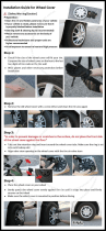
1. Place the bicycle so that the fork and the
rear wheel rest on the floor.
Turn the handlebar stem and the fork so that
the handlebar clamp points away from the
top tube of the frame.
Handlebar
Stem
Handlebar
Stem
Handlebar
Top
Tube
Rear
Wheel
Clamp
Clamp
Clamp
Washer
Washer
Bolts
Bolt
Bolt
Fork
ASSEMBLY
2. Remove the two bolts, the two washers, and
the handlebar clamp from the handlebar
stem.
3. Orient the handlebar so that the reflector
and the brake levers face forward and the
shifters face upward. Tip: Make sure to ori-
ent the handlebar so that the cables are
not twisted around the handlebar stem.
Tip: Start both bolts before tightening
either of them. While a second person
holds the handlebar in a centered position,
attach the handlebar with the two bolts, the
two washers, and the handlebar clamp.

8
5. Turn the bicycle over so that the seat and
the handlebar rest on the floor. Tip: Place a
towel under the handlebar to avoid dam-
aging the shifters.
Locate the front brake, which is connected to
a cable. Remove the two mounting bolts and
the two washers from the front brake.
4. See HOW TO USE A QUICK-RELEASE
LEVER on page 16 and pull the quick-
release lever on the seat post binder to the
open position.
Orient the seat post so that the nose of the
seat faces forward, and then insert the seat
post into the frame. IMPORTANT: Make
sure that the minimum insertion mark on
the seat post is not visible above the
frame; if the minimum insertion mark is
visible, the bicycle will be unsafe.
Move the quick-release lever so that it is
halfway between the open and closed posi-
tions. Next, finger-tighten the seat post
binder nut and push the quick-release lever
to the closed position; you should feel firm
resistance when you push the quick-
release lever. If there is no resistance, pull
the quick-release lever to the open position,
tighten the seat post binder nut a few more
turns, and then push the quick-release lever
to the closed position. Repeat this action
until you feel firm resistance when you push
the quick-release lever to the closed posi-
tion.
Seat
Seat Post
Binder Nut
Seat Post
Seat Post
Binder
Quick-release
Lever
Bolts
Cable
Front
Brake
Washer
Washer

9
7. Locate the quick-release lever for the front
wheel, which has a long axle, two springs,
and a wheel nut. Make sure to note the
position of the springs. Then, remove the
wheel nut and one spring.
Wheel
Nut
Axle
Springs
Quick-release
Lever
6. Hold the front brake near the bracket on the
fork. Orient the front brake so that the slot in
the front brake is on the inward side of the
fork and the end of the cable is pointing
upward.
Tip: Start both bolts before tightening
either of them. Attach the front brake to the
inside edge of the bracket on the fork with
the two mounting bolts and the two washers.
Bolts
Fork
Cable
Slot

10
9. Note: Complete assembly steps 9 to 11
only if your bicycle has a kickstand. If
your bicycle does not have a kickstand,
go to step 12.
Locate the kickstand assembly. Remove the
two screws and the main clamp. Then,
remove the screw and the support clamp.
8. Set the hub of the front wheel into the ends
of the fork; make sure that the disc fits
into the slot in the front brake. Next, insert
the axle of the quick-release lever through
the ends of the fork and the hub of the front
wheel. Then, place the spring on the end of
the axle and finger tighten the wheel nut a
few turns onto the axle.
See HOW TO USE A QUICK-RELEASE
LEVER on page 16 and move the quick-
release lever so that it is halfway between
the open and closed positions. Next, finger-
tighten the wheel nut and push the quick-
release lever to the closed position; you
should feel firm resistance when you
push the quick-release lever. If there is no
resistance, pull the quick-release lever to the
open position, tighten the wheel nut a few
more turns, and then push the quick-release
lever to the closed position. Repeat this
action until you feel firm resistance when
you push the quick-release lever to the
closed position.
Quick-
release
Lever
Hub
Wheel
Nut
Fork
Slot
Disc
Kickstand
Screws
Screw
Main
Clamp
Support
Clamp

11
10. IMPORTANT: The kickstand must be
attached to the chain stay on the side of
the bicycle opposite the chain. Hold the
kickstand near the chain stay and orient the
kickstand so that the support bracket is near
the seat stay.
Tip: Start all screws before tightening
any of them. While a second person holds
the kickstand in place, attach the kickstand
to the chain stay with the two screws and
the main clamp.
11. Attach the support bracket to the seat stay
with the screw and the support clamp. Tip:
If necessary, loosen the two screws in
the center of the kickstand and adjust the
support bracket so that it will fit around
the seat stay.
Then, tighten the two screws in the center
of the kickstand.
Main
Clamp
Support
Clamp
Chain
Stay
Seat
Stay
Kickstand
Kickstand
Screws
Screws
Screw
Seat
Stay

12
14. Pivot the cable cage into the interior of the
brake lever while firmly pulling the cable
away from the cable cage.
13. Locate the end of the front brake cable.
Look at the left brake lever on the han-
dlebar and make sure that the slots in
the brake lever, the lock ring, and the
barrel adjuster are aligned. If necessary,
turn the lock ring and the barrel adjuster
until the slots are aligned.
While another person squeezes the handle
of the left brake lever, use your fingers to
pivot the cable cage out of the interior of the
brake lever. With the other person still
squeezing the handle, insert the end of the
front brake cable into the circular hole in the
underside of the cable cage.
12. Turn the bicycle over so that the wheels rest
on the floor.
If there is a kickstand on your bicycle, move
the kickstand leg to the down position (see
HOW TO USE THE KICKSTAND on page
17) and rest the bicycle on the kickstand
leg. If necessary, loosen the screw on the
leg of the kickstand, adjust the leg to the
desired length, and then retighten the screw.
If there is no kickstand on your bicycle,
have another person hold the bicycle
steady.
Screw
Leg
Kickstand
Brake
Lever
Front Brake
Cable
Cable
Slots
Cable
Cage
Lock
Ring
Barrel
Adjuster
Brake
Lever
Cable
Cage
Slot

13
15. While the other person releases the handle
of the brake lever, pull the cable into the
slots in the brake lever, the lock ring, and
the barrel adjuster. Then, release the cable
so that the cable housing fits inside the bar-
rel adjuster.
Turn the lock ring so that the slot in the lock
ring is no longer aligned with the slot in the
brake lever.
Roll the bicycle forward and then squeeze
the left brake lever handle to test the front
brake. You should feel firm resistance as the
brake engages the disc on the front wheel.
16. Identify the left pedal, which is marked with
an “L” sticker. While another person holds
the bicycle frame, use an adjustable wrench
and firmly tighten the Left Pedal
counter-
clockwise
into the left crank arm. Tighten the
right pedal
clockwise
into the right crank
arm. Tighten both pedals as firmly as
possible.
17. Make sure that all parts are properly tightened before you use the bicycle. Note: Some extra parts may be
left over after assembly is completed.
Cable
Pedal
Brake
Lever
Crank
Arm
Slots

14
HOW TO ADJUST THE SEAT POST
For effective cycling, the seat should be at the proper
height. As you pedal, there should be a slight bend in
your knees when the pedals are in the lowest position.
To adjust the
height of the seat
post, first loosen
the quick-release
lever on the seat
post binder (see
HOW TO USE A
QUICK-RELEASE
LEVER on page
16). Next, slide the
seat post upward
or downward to
the desired posi-
tion. IMPORTANT:
Make sure that
the minimum
insertion mark on
the seat post is
not visible above the frame; if the minimum inser-
tion mark is visible, the bicycle will be unsafe.
Then, tighten the quick-release lever.
HOW TO ADJUST THE SEAT
You can adjust the angle and position of the seat to the
position that is most comfortable.
The correct angle for your seat is a matter of personal
preference. Begin by adjusting your seat so that the
top of the seat is parallel to the ground. Tip: It may be
helpful to use a level when you adjust the angle of
your seat.
If your bicycle has rear suspension, tilt the seat so that
the nose points downward slightly. When the rear sus-
pension unit compresses under your body weight, this
will result in a level seat.
You can also slide your seat forward or backward to
increase your comfort or to adjust the distance to the
handlebar.
To adjust the seat,
loosen the nuts on
the seat clamp a
few turns, and then
tilt the seat upward
or downward or
slide the seat for-
ward or backward
to the desired posi-
tion. Then, retight-
en the nuts.
HOW TO ADJUST THE HANDLEBAR
For effective cycling, the handlebar should be at the
proper angle. When you sit on your bicycle, your
shoulders, wrists, and the tops of the brake levers
should form a straight line.
To adjust the angle
of the handlebar,
loosen the two
bolts in the handle-
bar clamp, rotate
the handlebar to
the desired posi-
tion, and then
retighten the two
bolts in the handlebar clamp.
IMPORTANT: An improperly adjusted or tightened
handlebar or handlebar stem can cause you to
lose control of your bicycle and fall. Make sure the
handlebar and handlebar stem are properly posi-
tioned and tightened.
HOW TO OPERATE THE BICYCLE
Seat
Seat
Nut
Nut
Clamp
Seat
Post
Binder
Lever
Handlebar
Clamp
Bolts

15
HOW TO USE THE BRAKES
Use the brakes on your bicycle carefully. Always main-
tain a safe stopping distance between your bicycle
and other vehicles or objects. Adjust your stopping
distance and braking force to suit the cycling condi-
tions. To use your brakes, squeeze both brake levers
at the same time and shift your weight to the rear of
the seat. IMPORTANT: Use both brakes to slow or
stop your bicycle. Using only the front brake can
cause the rear wheel to lift off the ground, or the
front wheel to slip, which can cause you to lose
control of your bicycle and fall. Remove one foot
from a pedal before bringing your bicycle to a com-
plete stop. Be prepared to place your foot on the
ground when you stop the bicycle.
The brakes on your bicycle will not work as effectively
in wet conditions and stopping distances will increase.
Allow more time to slow or stop your bicycle in these
conditions.
IMPORTANT: Disc brakes and discs can become
very hot during use and can burn skin. Disc edges
may be sharp and can cut skin. Avoid touching the
disc or the disc brake when it is hot.
HOW TO SHIFT GEARS
Your bicycle is equipped with a derailleur system,
which shifts gears by derailing, or moving the chain
from one chainring or cog to another.
The left-hand shifter controls the front derailleur, and
the right-hand shifter controls the rear derailleur. Use
only one shifter at a time and keep pedaling whenever
you shift gears. To upshift to a larger chainring, push
the lever on the left-hand shifter. To downshift to a
smaller chainring, pull the lever on the left-hand
shifter. To upshift to a larger cog, push the lever on the
right-hand shifter. To downshift to a smaller cog, push
the button on the right-hand shifter.
Following these guidelines will provide quicker,
smoother shifting, will help avoid excessive chain and
gear wear, and will help avoid bent chains, derailleurs,
and chainrings. Choose the gear combination most
comfortable for the cycling conditions, one that allows
you to maintain a constant pedaling rate. Plan ahead
when shifting. Shift gears only when the pedals and
chain are moving forward. Do not attempt to shift
gears when stopped or when back-pedaling. Reduce
the force on the pedals when you shift; excessive
chain tension makes shifting difficult. Avoid shifting
when going over bumpy surfaces or over railroad
tracks; the chain may not shift properly or may fall off.
Brake
Lever
Brake
Lever
Lever
Lever
Button
Left-hand
Shifter
Right-hand
Shifter

16
HOW TO USE A QUICK-RELEASE LEVER
IMPORTANT: Operate a quick-release lever only by
hand. Never use a tool, such as a hammer, to
close or to open a quick-release lever.
A quick-
release
lever has
open and
closed
positions,
which are
marked on
the quick-release lever. To move a quick-release lever
to the open position, pull the quick-release lever out-
ward so that the word OPEN is visible. To move a
quick-release lever to the closed position, push the
quick-release lever inward so that the word CLOSED
is visible.
To tighten a quick-
release lever, first
move the quick-
release lever so
that it is halfway
between the open
position and the
closed position.
Next, finger-tighten the nut. IMPORTANT: Do not
tighten a quick-release lever like a wing nut; there
will not be enough force to hold the seat post or
the wheel in place.
Then, push the quick-release lever to the closed posi-
tion. IMPORTANT: You should feel firm resistance
when you push the quick-release lever to the
closed position; otherwise there will not be
enough force to hold the seat post or the wheel in
place.
If you do not feel firm resistance, pull the quick-
release lever to the open position, tighten the nut sev-
eral more turns, and push the quick-release lever to
the closed position. Repeat this action until you feel
firm resistance when you push the quick-release lever
to the closed position. Note: Make sure to orient the
quick-release lever so that it does not interfere with
any other part of the bicycle.
To loosen the quick-release lever, pull the quick-
release lever to the open position, and then loosen the
nut.
HOW TO INFLATE THE TIRES
IMPORTANT: Do not ride with underinflated tires
or you may crack the sidewalls of the tires and
damage the wheel rims.
The tires on your
bicycle have
schraeder valves.
Use a manual
hand pump to
inflate your tires to
the pressure
marked on the
sidewall of each
tire; do not use
compressed air to inflate your tires.
HOW TO ADJUST THE SUSPENSION
The rear suspension unit, which compresses under a
load, can be adjusted to accommodate cyclists of dif-
ferent body weights and to give either a soft or a hard
ride.
To adjust the rear
suspension unit,
turn the large col-
lar clockwise to
compress the
spring or counter-
clockwise to
release the spring.
As a starting point, adjust the collar until the spring is
compressed about 8mm. For a harder ride, turn the
collar to compress the spring further. For a softer ride,
turn the collar to loosen the spring.
Valves
Collar
Suspension
Unit
Open
Closed

17
HOW TO USE THE KICKSTAND
Your bicycle may be equipped with a kickstand that
allows you to rest the bicycle in an upright position
when you are not using it.
To use the kick-
stand, pivot the leg
on the kickstand
into a vertical posi-
tion. When you are
not using the kick-
stand, pivot the leg
into a horizontal
position. To adjust
the length of the
kickstand, loosen
the screw on the
leg of the kick-
stand, adjust the
leg to the desired
length, and then
retighten the screw.
HOW TO REMOVE THE FRONT WHEEL
To remove the front wheel, place the bicycle so that
the seat and the handlebars rest on the floor. Tip:
Place a towel under the handlebar to avoid damag-
ing the shifters.
Loosen the quick-release lever on the wheel (see
HOW TO USE A QUICK-RELEASE LEVER on page
16), and then remove the quick-release lever from the
hub and the fork. Next, lift the wheel out of the fork.
HOW TO ATTACH THE FRONT WHEEL
To attach the front wheel, place the bicycle so that the
seat and the handlebars rest on the floor. Tip: Place a
towel under the handlebar to avoid damaging the
shifters. Then, set the hub of the front wheel into the
ends of the fork; make sure that the disc on the hub
fits into the slot in the front brake.
The quick-release lever for the wheel consists of a
long axle, two springs, and a wheel nut. Place one
spring on the axle, and then insert the axle of the
quick-release lever through the ends of the fork and
the hub of the front wheel. Next, place the other spring
on the end of the axle and finger tighten the wheel nut
a few turns onto the axle. Then, tighten the quick-
release lever (see HOW TO USE A QUICK-RELEASE
LEVER on page 16).
After you reattach the front wheel, test the front wheel
to make sure that the quick-release lever is properly
tightened:
Pick up the bicycle and firmly hit the top of the tire
with your hand. When the quick-release lever is prop-
erly tightened, the front wheel will not be loose, move
from side to side, or come off. In addition, you will not
be able to rotate the quick-release lever parallel to the
wheel.
Roll the bicycle forward and then squeeze the left
brake lever handle to test the front brake. You should
feel firm resistance as the brake engages the disc on
the front wheel.
Quick-release
Lever
Hub
Nut
Fork
Slot
Disc
Screw
Leg
Kickstand

18
HOW TO REMOVE THE REAR WHEEL
To remove the rear wheel, first shift the chain to the
smallest rear cog and to the smallest front chainring
(see HOW TO SHIFT GEARS on page 15).
If your bicycle has
caliper brakes on
the rear wheel, you
must open the rear
brake. (Note: This
action is not nec-
essary if your bicy-
cle has a disc
brake on the rear
wheel.) To open
the brake, use one
hand to squeeze
the brake pads
firmly against the
wheel rim. With
your other hand,
disconnect the pipe from the link arm. Then, release
the brake pads and move the brake to the open posi-
tion. Note: Reverse these actions to close the brake.
Next, loosen the quick-release lever on the rear wheel
(see HOW TO USE A QUICK-RELEASE LEVER on
page 16). Pull the rear derailleur cage toward the rear
of the bicycle so that the chain moves out of the way,
and then slide the wheel out of the dropouts. Then,
release the rear derailleur cage.
HOW TO ATTACH THE REAR WHEEL
Note: If your bicycle has a caliper brake on the rear
wheel, make sure that the brake is open (see HOW
TO REMOVE THE REAR WHEEL on this page). Pull
the rear derailleur cage toward the rear of the bicycle
so that the chain moves out of the way.
Next, insert the hub of the rear wheel into the
dropouts in the frame. Rest the chain on the smallest
rear cog. Make sure that the hub of the rear wheel
fits securely into the dropouts. If your bicycle has a
disc brake on the rear wheel, make sure that the
disc on the hub fits into the slot in the rear brake.
The quick-release lever for the wheel consists of a
long axle, two springs, and a wheel nut. Place one
spring on the axle, and then insert the axle of the
quick-release lever through the dropouts and the hub
of the rear wheel. Next, place the other spring on the
end of the axle and finger tighten the wheel nut a few
turns onto the axle. Then, tighten the quick-release
lever (see HOW TO USE A QUICK-RELEASE LEVER
on page 16).
If your bicycle has a caliper brake on the rear wheel,
close the brake (see HOW TO REMOVE THE REAR
WHEEL on this page).
Pick up the bicycle and firmly hit the top of the tire
with your hand. When the quick-release lever is prop-
erly tightened, the rear wheel will not be loose, move
from side to side, or come off. In addition, you will not
be able to rotate the quick-release lever parallel to the
wheel.
Roll the bicycle forward and then squeeze the right
brake lever handle to test the rear brake. You should
feel firm resistance as the brake pad engages the rim
or the disc on the rear wheel.
Brake
Pads
Link
Arm
Pipe

19
It is your responsibility to ensure that your bicycle is in safe working condition before you cycle. Each time you
cycle, inspect your bicycle and make sure your bicycle meets the following standards:
1. Wheels are secured in the fork and rear drop-outs.
2. Wheels and spokes are straight and true with the hubs correctly adjusted and free from side play.
3. Front and rear brakes operate correctly.
4. Steering is free with no excess play and the handlebar is free from damage.
5. Tires are in good condition and inflated to the pressure shown on the sidewalls.
6. Gears are correctly adjusted.
7. Pedals and pedal cranks are securely tightened.
8. All nuts and bolts are tight.
9. Suspension is adjusted properly and suited to your cycling style.
10. Your riding position is comfortable.
If necessary, see HOW TO OPERATE THE BICYCLE on page 14 and make the appropriate adjustments or
have a qualified bicycle repair specialist make the appropriate adjustments.
PRE-CYCLING INSPECTION

1. Always wear a protective cycling helmet.
2. Make sure that none of your clothes can become
caught in the wheels or the drivetrain of your
bicycle.
3. Never hang bags or clothing on the handlebar;
this will affect your steering.
4. Never carry a passenger on your bicycle.
5. Select a gear that allows you to pedal between
fifty and seventy revolutions per minute, which is
similar to your resting heart rate. This will give you
better control of your bicycle and make it easier
for you to accelerate as you cycle.
6. Familiarize yourself with and observe the cycling
regulations and advice given in your local highway
code.
7. Obey all traffic regulations and local bylaws and
rules.
8. Always cycle defensively, be on your guard, and
be alert for problems and hazards.
9. Observe the road surface ahead. Avoid obstacles
such as potholes, gravel, and drains.
10. Use cycling lanes whenever possible.
11. Always cycle in single file.
12. Do not cycle too close to another vehicle, includ-
ing other bicycles.
13. Regularly look over your shoulder to observe traf-
fic approaching you from the rear, and always do
this before giving a hand signal. Use caution when
looking over your shoulder.
14. Give other road users clear hand signals to com-
municate your intended actions.
15. Be alert to vehicles pulling into your path. Also be
alert to doors of parked vehicles opening in your
path.
16. Never hold onto a moving vehicle or onto a sta-
tionary vehicle when stopped in traffic.
17. Use extra caution when cycling in wet conditions.
These conditions will affect your braking perfor-
mance. Allow extra time and stopping distance
when you use your brakes in these conditions.
Cycle slower when cornering or traveling over
areas with reduced traction. Do not cycle in icy
conditions.
18. If you cycle in the dark, make sure that your bicy-
cle has a headlight and reflectors. Also, make
sure to wear light-colored, reflective clothes when
cycling in the dark.
20
SAFE CYCLING TIPS
/