Power Max 826 OE Snowthrower

Toro Power Max 826 OE Snowthrower User manual

  • Hello! I am an AI chatbot trained to assist you with the Toro Power Max 826 OE Snowthrower User manual. I’ve already reviewed the document and can help you find the information you need or explain it in simple terms. Just ask your questions, and providing more details will help me assist you more effectively!
FormNo.3407-110RevA
PowerMax
®
826OESnowthrower
ModelNo.37772—SerialNo.400010798andUp
Operator'sManual
Introduction
WARNING
CALIFORNIA
Proposition65Warning
Thisproductcontainsachemicalorchemicals
knowntotheStateofCaliforniatocausecancer,
birthdefects,orreproductiveharm.
Theengineexhaustfromthisproduct
containschemicalsknowntotheStateof
Californiatocausecancer,birthdefects,
orotherreproductiveharm.
Thismachineisintendedtobeusedbyresidential
homeownersorprofessional,hiredoperators.Itis
designedforremovingsnowfrompavedsurfaces,such
asdrivewaysandsidewalks,andothersurfacesfor
trafconresidentialorcommercialproperties.Itisnot
designedforremovingmaterialsotherthansnow,noris
amodelwithapivotingscraperdesignedforclearingoff
gravelsurfaces.
Readthisinformationcarefullytolearnhowtooperateand
maintainyourmachineproperlyandtoavoidinjuryand
machinedamage.Youareresponsibleforoperatingthe
machineproperlyandsafely.
YoumaycontactTorodirectlyatwww .Toro.comformachine
andaccessoryinformation,helpndingadealer,ortoregister
yourmachine.
Wheneveryouneedservice,genuineToroparts,oradditional
information,contactanAuthorizedServiceDealerorToro
CustomerServiceandhavethemodelandserialnumbers
ofyourmachineready.Figure1identiesthelocationofthe
modelandserialnumbersonthemachine.Writethenumbers
inthespaceprovided.
g018884
Figure1
1.Modelandserialnumberlocation
ModelNo.
SerialNo.
Thismanualidentiespotentialhazardsandhassafety
messagesidentiedbythesafety-alertsymbol(Figure2),
whichsignalsahazardthatmaycauseseriousinjuryordeath
ifyoudonotfollowtherecommendedprecautions.
Figure2
1.Safety-alertsymbol
Thismanualuses2wordstohighlightinformation.
Importantcallsattentiontospecialmechanicalinformation
andNoteemphasizesgeneralinformationworthyofspecial
attention.
Important:Ifyouareusingthismachineabove1500m
(5,000ft)foracontinuousperiod,ensurethattheHigh
AltitudeKithasbeeninstalledsothattheenginemeets
CARB/EPAemissionregulations.TheHighAltitude
Kitincreasesengineperformancewhilepreventing
spark-plugfouling,hardstarting,andincreased
emissions.Onceyouhaveinstalledthekit,attach
thehigh-altitudelabelnexttotheserialdecalonthe
machine.ContactanyAuthorizedToroServiceDealer
toobtaintheproperHighAltitudeKitandhigh-altitude
labelforyourmachine.Tolocateadealerconvenientto
you,accessourwebsiteatwww.Toro.comorcontactour
ToroCustomerCareDepartmentatthenumber(s)listed
inyourEmissionControlWarrantyStatement.
©2016—TheToro®Company
8111LyndaleAvenueSouth
Bloomington,MN55420
Registeratwww.T oro.com.
OriginalInstructions(EN)
PrintedintheUSA
AllRightsReserved
*3407-110*A
Removethekitfromtheengineandrestoretheengine
toitsoriginalfactorycongurationwhenrunningthe
engineunder1500m(5,000ft).Donotoperateanengine
thathasbeenconvertedforhigh-altitudeuseatlower
altitudes;otherwise,youcouldoverheatanddamage
theengine.
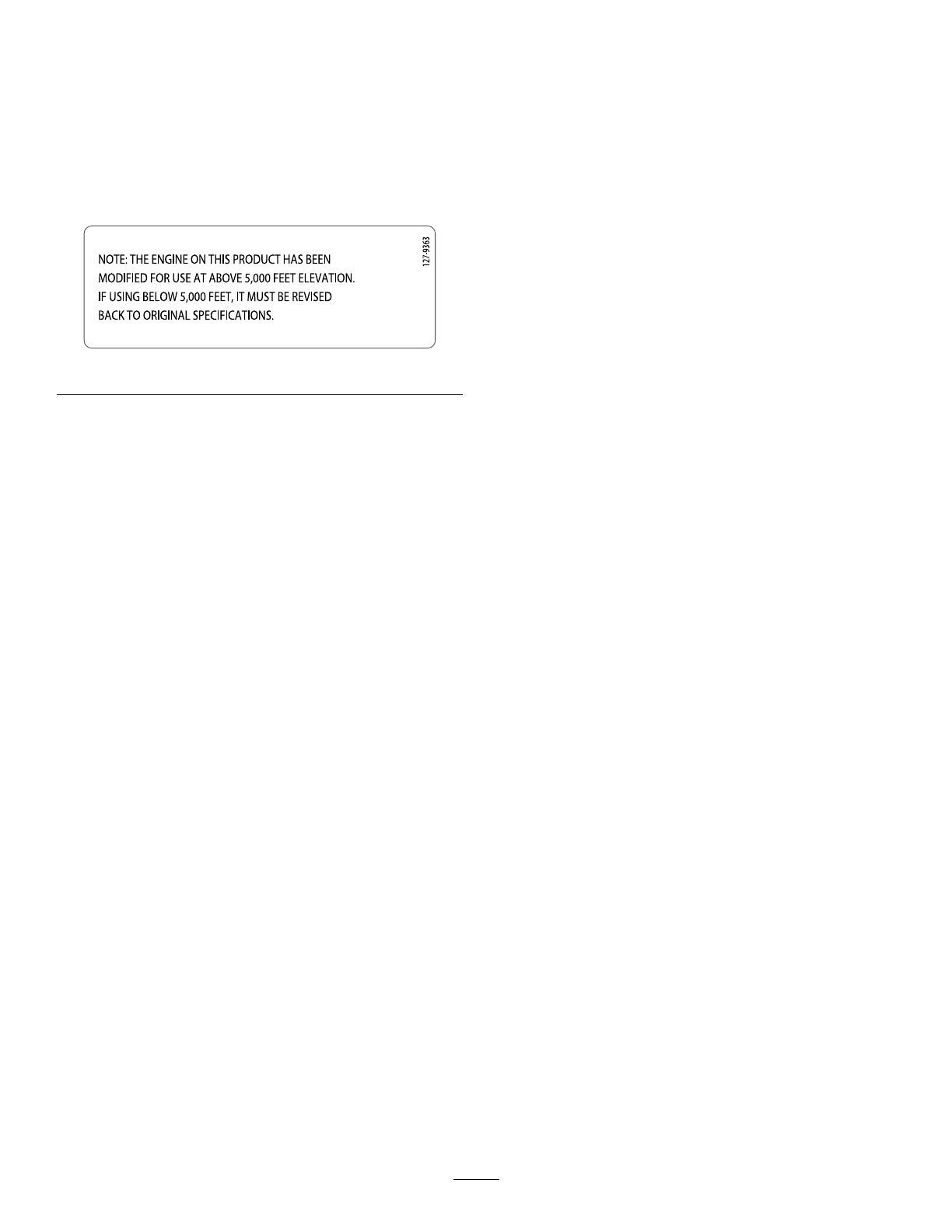
Ifyouareunsurewhetherornotyourmachinehasbeen
convertedforhigh-altitudeuse,lookforthefollowing
label(Figure3).
Figure3
ThissparkignitionsystemcomplieswithCanadianICES-002.
Contents
Introduction..................................................................1
Safety...........................................................................2
SafetyandInstructionalDecals.................................3
Setup............................................................................5
1InstallingtheUpperHandle....................................5
2InstallingtheTraction-ControlLinkage....................6
3InstallingtheChute...............................................7
4InstallingtheChute-ControlRod............................7
5CheckingtheEngine-OilLevel...............................8
6CheckingtheTirePressure.....................................8
7CheckingtheSkidsandScraper...............................8
8CheckingtheOperationoftheTraction
Drive.................................................................8
ProductOverview.........................................................10
Operation....................................................................10
BeforeOperation......................................................10
Safety....................................................................10
FreewheelingorUsingtheSelf-propelDrive...............10
FillingtheFuelTank...............................................11
DuringOperation.....................................................11
Safety....................................................................11
StartingtheEngine.................................................12
ShuttingOfftheEngine..........................................13
OperatingtheTractionDrive...................................14
OperatingtheSpeedSelector...................................14
OperatingtheAuger/ImpellerDrive.........................14
OperatingtheQuickStick®.....................................15
UncloggingtheDischargeChute..............................15
OperatingTips......................................................16
AfterOperation........................................................16
Safety....................................................................16
PreventingFreeze-upafterUse.................................16
Maintenance.................................................................17
RecommendedMaintenanceSchedule(s)......................17
MaintenanceSafety.................................................17
PreparingforMaintenance.......................................17
CheckingtheEngine-OilLevel.................................17
CheckingandAdjustingtheSkidsand
Scraper..............................................................18
CheckingandAdjustingtheTractionCable................18
CheckingandAdjustingtheAuger/Impeller
Cable................................................................19
CheckingtheAuger-Gearbox-OilLevel.....................19
ChangingtheEngineOil.........................................20
LubricatingtheHexShaft........................................20
ReplacingtheSparkPlug.........................................21
AdjustingtheDischarge-ChuteLatch........................22
ReplacingtheDriveBelts.........................................22
Storage........................................................................22
PreparingtheMachineforStorage............................22
RemovingtheMachinefromStorage.........................22
Troubleshooting...........................................................23
Safety
ThismachinecomplieswithANSIB71.3specications
ineffectatthetimeofproduction.
ReadandunderstandthecontentsofthisOperator’s
Manualbeforeyoustarttheengine.Ensurethateveryone
usingthisproductknowshowtousetheproductand
understandsthewarnings.
Donotputyourhandsorfeetnearmovingcomponents
onthemachine.
Donotoperatemachinewithoutallguardsandother
safetyprotectivedevicesinplaceandworkingonthe
machine.
Keepclearofanydischargeopening.Keepbystandersa
safedistanceawayfromthemachine.
Keepchildrenoutoftheoperatingarea.Neverallow
childrentooperatethemachine.
Shutofftheenginebeforeunclogging,servicing,or
fuelingthemachine.
Youcanndadditionalitemsofsafetyinformationintheir
respectivesectionsthroughoutthismanual.
2
SafetyandInstructionalDecals
Safetyandinstructiondecalsarelocatednearareasofpotentialdanger.Replacedamagedor
missingdecals.
121-6823
1.Fast
3.Slow
2.Forwardspeeds4.Reversespeeds
121-1239
OrderPartNo.121-1215
121-6817
1.Cuttingdismemberment,impellerandcutting
dismemberment,augerhazards—keepbystandersasafe
distanceawayfromthesnowthrower.
3
121-1240
OrderPartNo.120-7194
1.Tractiondrive—squeezethelevertoengage;releasethe
levertodisengage.
4.Cuttingdismembermenthazard,impeller—keepaway
frommovingparts;removetheignitionkeyandreadthe
instructionsbeforeservicingorperformingmaintenance.
2.Warning—readtheOperatorsManual.5.Thrownobjecthazard—keepbystandersasafedistance
awayfromthesnowthrower.
3.Cutting/dismembermenthazard,impeller—donotplaceyour
handinthechute;shutofftheenginebeforeleavingthe
operatingposition,usethetooltoclearthechute.
6.Auger/impellerdrive—squeezethelevertoengage;release
thelevertodisengage.
Briggs&StrattonPartNo.273676
1.Stop
3.Fast
2.Slow
Briggs&StrattonPartNo.275949
1.Chokeon(choke)2.Chokeoff(run)
Briggs&StrattonPartNo.276925
1.Warning—readthe
Operator'sManual.
3.Warning—toxicgas
inhalationhazard.
2.Warning—rehazard.
4.Warning—hot
surface/burnhazard.
Briggs&StrattonPartNo.277566
1.Whenstartingacold
engine,closethechoke
andpresstheprimertwo
times.
2.Whenstartingawarm
engine,openthechoke
anddonotpressthe
primer.
Briggs&StrattonPartNo.277588
1.Primer3.Ignitionkeyout
(Engine—shutoff)
2.Ignitionkeyin
(Engine—run)
Briggs&StrattonPartNo.278866
1.Fuel—on
2.Fuel—off
4
Setup
LooseParts
Usethechartbelowtoverifythatallpartshavebeenshipped.
ProcedureDescription
Qty.
Use
Handlebolt2
Curvedwasher
2
1
Locknut2
Installtheupperhandle.
Hairpincotter2
2
Flatwasher3
Installthetraction-controllinkage.
Nut2
Carriagebolt
2
3
Flatwasher2
Installthechute.
Carriagebolt
2
4
Locknut2
Installthechute-controlrod.
5
Nopartsrequired
Checktheengine-oillevel.
6
Nopartsrequired
Checkthetirepressure.
7
Nopartsrequired
Checktheskidsandscraper.
8
Nopartsrequired
Checktheoperationofthetractiondrive.
1
InstallingtheUpperHandle
Partsneededforthisprocedure:
2Handlebolt
2
Curvedwasher
2Locknut
Procedure
1.Liftandrotatetheupperhandleandpositionitover
thelowerhandle(Figure4).
2.Install2handlebolts,2curvedwashers,and2locknuts
inthelowerhandleholes(Figure4).
g019003
Figure4
5
2
InstallingtheTraction-Control
Linkage
Partsneededforthisprocedure:
2Hairpincotter
3Flatwasher
Procedure
1.Insertthelowerendoftherodintothelowerlinkarm
sothatthebentendofthespeed-controlrodfaces
rearward(Figure5).
g019004
Figure5
2.Securethelowerendofthespeed-controlrodwitha
atwasherandahairpincotter(Figure5).
3.Placeaatwasheronthetrunnion(Figure6).
Figure6
1.Speed-selectorlever
3.Innerwasher
2.Trunnion
4.Outerwasher
4.Shiftthespeed-selectorleverintoPositionR2.
5.Rotatethelowerlinkarmfullyupward
(counterclockwise)asshowninFigure7.
g019378
Figure7
6.Pulluponthespeed-controlrodandinsertthe
trunnionintotheholeinthespeed-selectorlever
(Figure6).
Note:Ifthetrunniondoesnottintothehole
whenyouliftuponthespeed-controlrod,rotatethe
trunnionupwardordownwardonthespeed-control
roduntilitts.
7.Securethetrunnionandupperendofthespeed-control
rodwithawasherandahairpincotter.
Note:Foreasierinstallation,lookdownthroughthe
openinginthespeedselector(Figure8).
Figure8
1.Speedselector
6
3
InstallingtheChute
Partsneededforthisprocedure:
2Nut
2
Carriagebolt
2Flatwasher
Procedure
1.Placethechuteontheframeandthealignthedischarge
chutemounttothechutesupport.
3
1
2
g019379
Figure9
1.Carriagebolt
3.Nut
2.Flatwasher
2.Securethedischargechutemountusing2bolts,2nuts,
and2atwashers.
4
InstallingtheChute-Control
Rod
Partsneededforthisprocedure:
2
Carriagebolt
2Locknut
Procedure
1.UnwraptheQuickStickandrotateitsothatitis
uprightandinthecenter.
2.Holdthebluetriggercapdownandpulltheleverfully
rearward.
Note:Thedischargechuteanddeectorshouldface
forward.Iftheydonot,holdthebluetriggercap
down(butdonotmovetheQuickStick)androtatethe
dischargechuteuntiltheydo.
3.Aligntheattenedbackendofthelongchute-control
rodwiththeattenedfrontendoftheshortrod
thatextendsfromthecontrolpanelsothattheynest
together(Figure10).
Figure10
1.Shortrod
2.Longchute-controlrod
4.Insertthefrontendoftherodintotheopeningin
thebackofthechute-gearcoveruntilitslidesintothe
chutegear(Figure11).
7
g018885
Figure11
5.Aligntheholesinthenestedendsoftherodsand
insert2carriagebolts(intheloose-partsbag)through
theshortrodfromtheleftsideofthemachine(from
theoperatingposition).
6.Insertthecableclipthatsupportsthedeectorcable
ontotheforwardcarriagebolt,andsecurethecarriage
boltswithlocknutsfromtheloose-partsbag(Figure
12).
Figure12
1.Cableclip2.Deectorcable
7.HoldthebluetriggercapdownandrotatetheQuick
Stickinacircletoensurethatthechuteanddeector
operatesmoothly.
5
CheckingtheEngine-OilLevel
NoPartsRequired
Procedure
Note:Yourmachinecomeswithoilintheengine
crankcase.Beforestartingtheengine,checktheoillevel
andaddoilifnecessary.
RefertoCheckingtheEngine-OilLevel(page17).
6
CheckingtheTirePressure
NoPartsRequired
Procedure
Thetiresareoverinatedatthefactoryforshipping.Reduce
thepressureequallyinbothtirestobetween116and137
kPa(17and20psi).
7
CheckingtheSkidsand
Scraper
NoPartsRequired
Procedure
RefertoCheckingandAdjustingtheSkidsandScraper(page
18).
8
8
CheckingtheOperationofthe
TractionDrive
NoPartsRequired
Procedure
CAUTION
Ifthetractiondriveisnotproperlyadjusted,the
machinemaymoveinthedirectionoppositeof
whatyouintended,causinginjuryand/orproperty
damage.
Carefullycheckthetractiondriveandadjustit
properly,ifnecessary.
Note:Tochecktheoperationofthetractiondrive,the
self-propelfeaturemustbeengagedbyensuringthewheels
arepinnedintheaxle.RefertoFreewheelingorUsingthe
Self-propelDrive(page10).
1.Starttheengine;refertoStartingtheEngine(page12).
2.MovethespeedselectortoPositionR1;referto
OperatingtheSpeedSelector(page14).
3.Squeezetheleft(traction)levertothehandgrip(Figure
13).
Figure13
Themachineshouldmoverearward.Ifthemachine
doesnotmoveormovesforward,completethe
following:
A.Releasethetractionleverandshutofftheengine.
B.Disconnectthetrunnionfromthespeed-selector
lever(Figure6).
C.Turnthetrunniondownward(clockwise)onthe
speed-controlrod(Figure6).
D.Connectthetrunniontothespeed-selectorlever
(Figure6).
4.Releasethetractionlever.
5.MovethespeedselectortoPosition1;referto
OperatingtheSpeedSelector(page14).
6.Squeezetheleft(traction)levertothehandgrip(Figure
13).
Themachineshouldmoveforward.Ifthemachine
doesnotmoveormovesrearward,completethe
following:
A.Releasethetractionleverandshutofftheengine.
B.Disconnectthetrunnionfromthespeed-selector
lever(Figure6).
C.Turnthetrunnionupward(counterclockwise)on
thespeed-controlrod(Figure6).
D.Connectthetrunniontothespeed-selectorlever
(Figure6).
7.Ifyoumadeanyadjustments,repeatthisprocedure
untilnoadjustmentsarerequired.
Important:Ifthemachinemoveswhenthetraction
leverisinthereleasedposition,checkthetractioncable
(refertoCheckingandAdjustingtheTractionCable
(page18))ortakethemachinetoanAuthorizedService
Dealerforservice.
9
ProductOverview
g018887
Figure14
1.Handgrip(2)
9.Dischargechute
2.Auger/impellerlever10.Scraper
3.Speed-selectorlever
11.Auger
4.QuickStick®
discharge-chutecontrol
12.Skid(2)
5.Tractionlever13.Electric-startbutton
6.Fuel-tankcap14.Electric-startplug-in
7.Oil-lltube/dipstick15.Snow-cleanouttool
8.Chutedeector
g018888
Figure15
1.Choke
5.Recoil-starthandle
2.Ignitionswitch
6.Oil-drainplug
3.Fuel-shutoffvalve
7.Primer
4.Throttle
Figure16
1.Snow-cleanouttool(attachedtothehandle)
Operation
BeforeOperation
Safety
Useextensioncordsandreceptaclesasspeciedby
themanufacturerforallmachineswithelectric-starting
motors.
Donotoperatethemachinewithoutwearingadequate
wintergarments.Avoidloose-ttingclothingthatcanget
caughtinmovingparts.Wearsubstantial,slip-resistant
footwearthatwillimprovefootingonslipperysurfaces.
Alwayswearsafetyglassesoreyeprotectionduring
operationorwhileperforminganadjustmentorrepairto
protectyoureyesfromforeignobjectsthatthemachine
maythrow .
Thoroughlyinspecttheareawhereyouwillusethe
machineandremovealldoormats,sleds,boards,wires,
andotherforeignobjects.
Ifashield,safetydevice,ordecalisdamaged,illegible,or
lost,repairorreplaceitbeforebeginningoperation.Also,
tightenanyloosefasteners.
FreewheelingorUsingthe
Self-propelDrive
Youcanoperatethesnowthrowerwiththeself-propelfeature
engagedordisengaged(freewheeling).
Tofreewheel,slidethewheelsinwardandinserttheaxle
pinsthroughtheaxleholes,butnotthroughthewheelhubs
(Figure17).
g019015
Figure17
Toself-propel,axlepinthroughtheholesinthewheelhubs
andtheinneraxleholes(Figure18).
10
g019014
Figure18
FillingtheFuelTank
Forbestresults,useonlyclean,fresh,unleadedgasoline
withanoctaneratingof87orhigher((R+M)/2rating
method).
Oxygenatedfuelwithupto10%ethanolor15%MTBE
byvolumeisacceptable.
Donotuseethanolblendsofgasoline(suchasE15
orE85)withmorethan10%ethanolbyvolume.
Performanceproblemsand/orenginedamagemayresult
whichmaynotbecoveredunderwarranty.
Donotusegasolinecontainingmethanol.
Donotstorefueleitherinthefueltankorfuelcontainers
overthewinterunlessyouuseafuelstabilizer.
Donotaddoiltogasoline.
Important:Toreducestartingproblems,addfuel
stabilizertothefuelallseason,mixingitwithgasoline
lessthan30daysold.
g018889
Figure19
1.Donotllabovethebottomofthefuel-tankneck.
DuringOperation
Safety
Rotatingaugerbladescaninjurengersorhands.
Staybehindthehandlesandawayfromthedischarge
openingwhileoperatingthemachine.Keepyourface,
hands,feet,andanyotherpartofyourbodyor
clothingawayfrommovingorrotatingparts.
Neverdirectthedischargetowardpeopleorareaswhere
propertydamagecanoccur.
Exercisecautiontoavoidslippingorfalling.Alwaysbe
sureofyourfooting,andkeeparmholdonthehandles.
Walk;neverrun.
Exerciseextremecautionwhenoperatingonslopes.
Neveroperatethemachinewithoutgoodvisibilityor
light.
Lookbehindandusecarewhenbackingupwiththe
machine.
Whennotactivelyclearingsnow ,disengagepowertothe
rotorblades.
Useextensioncordsandreceptaclesasspeciedby
themanufacturerforallmachineswithelectric-starting
motors.
Donotattempttoclearsnowfromagravelorcrushed
rocksurface.Thisproductisintendedforuseonlyon
pavedsurfaces.
Donotusethemachineonaroof.
Neverattempttomakeanyadjustmentswhiletheengine
isrunning(exceptwhenspecicallyrecommendedby
manufacturer).
Stayalertforhiddenhazardsortrafc.
Afterstrikingaforeignobject,shutofftheengine,
removetheignitionkey,thoroughlyinspectthemachine
foranydamage,andrepairthedamagebeforestarting
andoperatingthemachine.
Ifthemachineshouldstarttovibrateabnormally,shutoff
theengineandcheckimmediatelyforthecause.
Donotruntheengineindoors,exceptwhenstarting
theengineandfortransportingthemachineinorout
ofthebuilding.Opentheoutsidedoors;exhaustfumes
aredangerous.
Donotoverloadthemachinecapacitybyattemptingto
clearsnowattoofastarate.
Nevertouchahotengineormufer.
Thoroughlyinspecttheelectricalcordbeforeplugging
itintoapowersource.Ifthecordisdamaged,donot
useittostartthemachine.Replacethedamagedcord
immediately.Unplugthepowercordwheneveryouare
notstartingthemachine.
11
StartingtheEngine
1.Checktheengine-oillevel.RefertoCheckingthe
Engine-OilLevel(page17).
2.Turnthefuel-shutoffvalve1/4turncounterclockwise
toopenit(Figure20).
Figure20
3.Inserttheignitionkey(Figure21).
g018890
Figure21
1.Ignitionkey
4.Firmlypushintheprimerwithyourthumbasindicated
bythetablebelow,holdingtheprimerinforasecond
beforereleasingiteachtime(Figure22).
Temperature
SuggestedNumberof
Primes
-9°C(15°F)andabove
2
Below-9°C(15°F)
4
Figure22
5.RotatethechoketotheCHOKEposition(Figure23).
g018892
Figure23
6.MovethethrottletotheFASTposition(Figure24).
Figure24
7.Startthemachinepullingtherecoil-starthandleor
pressingtheelectric-starterbutton(Figure25).
12
g018893
Figure25
1.Electric-startbutton3.Recoil-starthandle
2.Electric-startplug-in
Tousetheelectricstarter(electricstartonly),connecta
powercordtotheelectric-startplug-inrstandthen
toagroundfaultcircuitinterrupter(GFCI)power
outlet.UseonlyaUL-listed,16-gaugepowercord
recommendedforoutdoorusethatisnotlongerthan
15m(50ft).
Important:Donotuseawornordamagedpower
cord.
WARNING
Theelectricalcordcanbecomedamaged,
causingashockorre.
Thoroughlyinspecttheelectricalcordbefore
usingthemachine.Ifthecordisdamaged,
donotoperatethemachine.Replaceorrepair
thedamagedcordimmediately.Contactan
AuthorizedServiceDealerforassistance.
Important:Topreventdamagingtheelectric
starter,runitinshortcycles(5secondsmaximum,
thenwaitoneminutebeforetryingtostartit
again).Iftheenginestilldoesnotstart,take
themachinetoanAuthorizedServiceDealerfor
service.
8.Disconnectthepowercordfromthepoweroutletrst
andthenfromthemachine(electricstartonly).
9.Allowtheenginetowarmupforseveralminutes,
movethechoketowardtheRUNposition.Waitforthe
enginetorunsmoothlybeforeeachchokeadjustment.
CAUTION
Ifyouleavethemachinepluggedintoapower
outlet,someonecaninadvertentlystartthemachine
andinjurepeopleordamageproperty.
Unplugthepowercordwheneveryouarenot
startingthemachine.
ShuttingOfftheEngine
1.MovethethrottletotheSLOWpositionandthentothe
STOPposition(Figure26).
Figure26
2.Waitforallmovingpartstostopbeforeleavingthe
operatingposition.
3.Removetheignitionkey.
4.Closethefuel-shutoffvalvebyrotatingitclockwise
(Figure27).
Figure27
5.Pulltherecoil-starthandle3or4times.Thishelps
preventtherecoilstarterfromfreezingup.
13
OperatingtheTractionDrive
CAUTION
Ifthetractiondriveisnotproperlyadjusted,the
machinemaymoveinthedirectionoppositeof
whatyouintended,causinginjuryand/orproperty
damage.
Carefullycheckthetractiondriveandadjustit
properly,ifnecessary;referto8Checkingthe
OperationoftheTractionDrive(page8)formore
information.
Important:Ifthemachinemoveswhenthetraction
leverisinthereleasedposition,checkthetractioncable;
refertoCheckingandAdjustingtheTractionCable
(page18)ortakethemachinetoanAuthorizedService
Dealerforservice.
1.Toengagethetractiondrive,squeezetheleft(traction)
levertothehandgrip(Figure28).
Figure28
2.Tostopthetractiondrive,releasethetractionlever.
OperatingtheSpeedSelector
Thespeedselectorhas6forwardand2reversegears.
Tochangespeeds,releasethetractionleverandshiftthe
speed-selectorlevertothedesiredposition(Figure29).The
leverlocksinanotchateachspeedselection.
Figure29
OperatingtheAuger/Impeller
Drive
1.Toengagetheauger/impellerdrive,squeezetheright
(auger/impeller)levertothehandgrip(Figure30).
Figure30
2.Tostoptheaugerandimpeller,releasetherightlever.
Important:Whenyouengageboththe
auger/impellerleverandthetractionlever,the
tractionleverlockstheauger/impellerleverdown,
freeingyourrighthand.Toreleasebothlevers,
simplyreleasetheleft(traction)lever.
3.Iftheaugerandimpellercontinuetorotatewhenyou
releasetheauger/impellerlever,donotoperatethe
machine.Checktheauger/impellercable;referto
CheckingandAdjustingtheAuger/ImpellerCable
(page19)andadjustitifnecessary.Otherwise,takethe
machinetoanAuthorizedDealerforservice.
WARNING
Iftheaugerandimpellercontinuetorotate
whenyoureleasetheauger/impellerlever,
donotoperatethemachine,asyoucould
seriouslyinjureyourselforothers.
TakeittoanAuthorizedServiceDealerfor
service.
14
OperatingtheQuickStick®
HoldthebluetriggercapdowntousetheQuickStickto
movethedischargechuteandthechutedeector.Releasethe
triggercaptolockthedischargechuteandchutedeector
intoposition(Figure31).
Figure31
MovingtheDischargeChute
HoldthebluetriggercapdownandmovetheQuickStick
tothelefttomovethedischargechutetotheleft;movethe
QuickSticktotherighttomovethedischargechutetothe
right(Figure32).
g018894
Figure32
Ifthechutedoesnotmove,refertoAdjustingthe
Discharge-ChuteLatch(page22).
Ifthechutedoesnotturnasfartotheleftasitdoestothe
right,ensurethatthecableisroutedtotheinsideofthe
handles.Referto1InstallingtheUpperHandle(page5).
Ifthechutedoesnotlockintoplacewhenyourelease
thetriggercap,refertoAdjustingtheDischarge-Chute
Latch(page22).
MovingtheChuteDeector
HoldthebluetriggercapdownandmovetheQuickStick
forwardtolowerthechutedeector;moveitrearwardtoraise
thechutedeector(Figure33).
Figure33
UncloggingtheDischarge
Chute
WARNING
Iftheauger/impellerisrunningbutthereisno
snowcomingoutofthedischargechute,the
dischargechutemaybeclogged.
Neveruseyourhandstoclearacloggeddischarge
chute.Thiscouldresultinpersonalinjury.
Tounclogthedischargechute,stayintheoperating
positionandreleasetheleft(traction)lever.While
runningtheauger/impeller,pushdownonthehandlesto
raisethefrontofthemachineafewcentimeters(inches)
offthepavement.Thenliftthehandlesquicklytobump
thefrontofthemachineonthepavement.Repeatif
necessaryuntilastreamofsnowcomesoutthedischarge
chute.
Ifyoucannotunclogthedischargechutebybumping
thefrontofthemachine,shutofftheengine,waitfor
allmovingpartstostop,andusethesnow-cleanout
tool;neveruseyourhand.
Important:Uncloggingthedischargechuteby
bumpingthefrontofthemachineonthepavement
maycausetheskidstomove.Adjusttheskidsand
tightentheskidboltssecurely.
15
OperatingTips
DANGER
Whenthemachineisinoperation,theimpellerand
augerrotateandcaninjureoramputatehandsor
feet.
Beforeadjusting,cleaning,inspecting,
troubleshooting,orrepairingthemachine,shut
offtheengineandwaitforallmovingparts
tostop.Disconnectthewirefromthespark
plugandkeepitawayfromtheplugtoprevent
someonefromaccidentallystartingtheengine.
Removeanobstructionfromthedischarge
chute;refertoUncloggingtheDischargeChute
(page15).Ifnecessary,usethesnow-cleanout
tool,notyourhands,toremoveanobstruction
fromthedischargechute.
Staybehindthehandlesandawayfromthe
dischargeopeningwhileoperatingthemachine.
Keepface,hands,feet,andanyotherpartof
yourbodyorclothingawayfromconcealed,
moving,orrotatingparts.
WARNING
Theimpellercanthrowstones,toys,andother
foreignobjectsandcauseseriouspersonalinjuryto
theoperatorortobystanders.
Keeptheareatobeclearedfreeofallobjects
thattheaugercouldpickupandthrow.
Keepallchildrenandpetsawayfromthearea
ofoperation.
AlwayssetthethrottletotheFASTpositionwhen
throwingsnow .
Iftheengineslowsdownunderaloadorthewheelsslip,
shiftthemachineintoalowergear.
Ifthefrontofthemachineridesup,shiftthemachine
intoalowergear.Ifthefrontcontinuestorideup,liftup
onthehandles.
AfterOperation
Safety
Neverstorethemachinewithfuelinthefueltankinsidea
buildingwhereignitionsourcesarepresent,suchashot
waterheaters,spaceheaters,orclothesdryers.Allowthe
enginetocoolbeforestoringinanyenclosure.
Whenstoringthemachineformorethan30days,referto
Storage(page22)forimportantdetails.
PreventingFreeze-upafterUse
Insnowyandcoldconditions,somecontrolsandmoving
partsmayfreeze.Donotuseexcessiveforcewhen
tryingtooperatefrozencontrols.Ifyouhavedifculty
operatinganycontrolorpart,starttheengineandletit
runforafewminutes.
Afterusingthemachine,lettheenginerunforafew
minutestopreventmovingpartsfromfreezing.Engage
theauger/impellertoclearanyremainingsnowfrom
insidethehousing.RotatetheQuickSticktopreventit
fromfreezing.Shutofftheengine,waitforallmoving
partstostop,andremovealliceandsnowfromthe
machine.
Withtheengineoff,pulltherecoil-starthandleseveral
timesandpushtheelectric-starterbuttononcetoprevent
therecoilstarterandelectricstarterfromfreezingup.
16
Maintenance
Note:Determinetheleftandrightsidesofthemachinefromthenormaloperatingposition.
RecommendedMaintenanceSchedule(s)
MaintenanceService
Interval
MaintenanceProcedure
Aftertherst2hours
Inspectthetractioncableandadjustitifnecessary.
Inspecttheauger/impellercableandadjustitifnecessary.
Aftertherst5hours
Changetheengineoil.
Beforeeachuseordaily
Checktheengine-oillevelandaddoilifnecessary.
Yearly
Checktheskidsandthescraperandadjustthemifnecessary.
Inspectthetractioncableandadjustorreplaceitifnecessary.
Inspecttheauger/impellercableandadjustorreplaceitifnecessary.
Checktheauger-gearboxoilandaddoilifnecessary.
Changetheengineoil.
Lubricatethehexshaft.
Replacethesparkplug.
Yearlyorbeforestorage
Checktheairpressureinthetiresandinatethemto116to137kPa(17to20psi).
Drainthefuelfromthefueltankandruntheenginetodryoutthefueltankand
thecarburetorattheendoftheseason.
HaveanAuthorizedServiceDealerinspectandreplacethetractiondrivebeltand/or
theauger/impellerdrivebelt,ifnecessary.
Important:Youcanndmoreinformationaboutmaintainingandservicingyourmachineatwww.Toro.com.
Important:Refertoyourengineowner'smanualforadditionalmaintenanceprocedures.Forengineadjustments,
repairs,orwarrantyservicenotcoveredinthismanual,contactanAuthorizedBriggs&StrattonServicingDealer.
MaintenanceSafety
Readthefollowingsafetyprecautionsbeforeperformingany
maintenanceonthemachine:
Beforeperforminganymaintenance,service,or
adjustment,shutofftheengineandremovethekey.If
majorrepairsareeverneeded,contactanAuthorized
ServiceDealer.
Checkallfastenersatfrequentintervalsforproper
tightnesstoensurethatthemachineisinsafeworking
condition.
Maintainorreplacesafetyandinstructionlabels,as
necessary.
Donotchangethegovernorsettingsontheengine.
PurchaseonlygenuineTororeplacementpartsand
accessories.
PreparingforMaintenance
1.Movethemachinetoalevelsurface.
2.Shutofftheengineandwaitforallmovingpartsto
stop.
3.Disconnectthespark-plugwire.RefertoReplacing
theSparkPlug(page21).
CheckingtheEngine-OilLevel
ServiceInterval:Beforeeachuseordaily—Checkthe
engine-oillevelandaddoilifnecessary.
1.Removethedipstick,wipeitclean,thenfullyinstall
thedipstick.
2.Removethedipstickandchecktheoillevel(Figure34).
IftheoillevelisbelowtheAddmarkonthedipstick,
addoil.RefertoChangingtheEngineOil(page20).
g018886
Figure34
17
CheckingandAdjustingthe
SkidsandScraper
ServiceInterval:Yearly—Checktheskidsandthescraper
andadjustthemifnecessary.
Checktheskidsandthescrapertoensurethattheaugerdoes
notcontactthepavedorgravelsurface.Adjusttheskidsand
thescraperasneededtocompensateforwear.
1.Checkthetirepressure;referto6CheckingtheTire
Pressure(page8).
2.Loosenthenutsthatsecurebothskidstotheauger
sidesuntiltheskidsslideupanddowneasily.
g019046
1
Figure35
1.3mm(1/8inch)
Important:Theaugerbladesmustbesupported
abovethegroundbytheskids.
3.Ensurethatthescraperis3mm(1/8inch)aboveand
paralleltoalevelsurface.
Note:Ifthepavementiscracked,rough,oruneven,
adjusttheskidstoraisethescraper.Forgravelsurfaces,
adjusttheskidsfurtherdowntopreventthemachine
frompickinguprocks.
4.Movetheskidsdownuntiltheyareevenwiththe
ground.
5.Firmlytightenthenutsthatsecurebothskidstothe
augersides.
Note:Toquicklyadjusttheskidsiftheyloosen,
supportthescraper3mm(1/8inch)offthepavement,
thenadjusttheskidsdowntothepavement.
Note:Iftheskidsbecomeexcessivelyworn,youcan
turnthemoverandsettheunusedsidetowardthe
pavement.
CheckingandAdjustingthe
TractionCable
ServiceInterval:Aftertherst2hours—Inspectthe
tractioncableandadjustitifnecessary.
Yearly—Inspectthetractioncableandadjustor
replaceitifnecessary.
Ifthemachinedoesnotdriveintheforwardorreversespeeds
oritdriveswhenyoureleasethetractionlever,adjustthe
tractioncable.
Iftheleft(traction)cableisnotproperlyadjusted,dothe
followingsteps:
1.Loosenthejamnut.
2.Engagethetractionleverandholditinplace(Figure
36).
Figure36
3.Loosenortightentheturnbuckletoadjustthespring
lengthto5.5cm(2.18inches)asshowninFigure37.
3
g019048
4
Figure37
1.Jamnut
3.Spring
2.Turnbuckle
4.5.5cm(2.18inches)
18
4.Tightenthejamnut(Figure37),ensuringthereisslight
tensiononthecable.
5.Ifthetractioncableisproperlyadjustedbutaproblem
remains,contactanAuthorizedServiceDealer.
CheckingandAdjustingthe
Auger/ImpellerCable
ServiceInterval:Aftertherst2hours—Inspectthe
auger/impellercableandadjustitif
necessary.
Yearly—Inspecttheauger/impellercableandadjust
orreplaceitifnecessary.
1.Loosenthejamnut.
2.Engagetheauger/impellerleverandholditinplace
(Figure38).
Figure38
3.Loosenortightentheturnbuckletoadjustthespring
lengthto7cm(2.75inches)asshowninFigure39.
2
1
3
g019047
4
Figure39
1.Jamnut
3.Spring
2.Turnbuckle
4.7cm(2.75inches)
4.Tightenthejamnut(Figure39),ensuringthereisslight
tensiononthecable.
5.Iftheauger/impellercableisproperlyadjustedbut
aproblemremains,contactanAuthorizedService
Dealer.
Checkingthe
Auger-Gearbox-OilLevel
ServiceInterval:Yearly—Checktheauger-gearboxoiland
addoilifnecessary.
1.Movethemachinetoalevelsurface.
2.Cleantheareaaroundthepipeplug(Figure40).
1
G016782
Figure40
1.Pipeplug
3.Removethepipeplugfromthegearbox.
4.Checktheoillevelinthegearbox.Theoilshouldbe
9.5mm(3/8inch)belowthelleropening.
5.Iftheoillevelislow ,addGL-5orGL-6,SAE80-90
EPgearoillubricanttothegearboxuntiltheoillevelis
9.5mm(3/8inch)belowthelleropening.
Note:Donotusesyntheticoil.
6.Installthepipepluginthegearbox.
19
ChangingtheEngineOil
ServiceInterval:Aftertherst5hours—Changetheengine
oil.
Yearly—Changetheengineoil.
Ifpossible,runtheengineforafewsecondsbeforechanging
theoilbecausewarmoilowsbetterandcarriesmore
contaminants.
UseautomotivedetergentoilwithanAPIserviceclassication
ofSF,SG,SH,SJ,SL,orhigher.Refertoyourengineowner's
manual.
UseFigure41belowtoselectthebestoilviscosityforthe
outdoortemperaturerangeexpected:
g019049
Figure41
EngineOilCapacities
Model
EngineOilCapacity
37772
0.53to0.59L(18to20oz)
1.Cleantheareaaroundtheoil-draincap(Figure42).
Figure42
1.Oil-draincap
2.Slideanoil-drainpanunderthedrainextensionand
removetheoil-draincap.
3.Draintheoil.
Note:Disposeoftheusedoilproperlyatalocal
recyclingcenter.
4.Installtheoil-draincap.
5.Fillthecrankcasewithoil.
LubricatingtheHexShaft
ServiceInterval:Yearly—Lubricatethehexshaft.
Lightlylubricatethehexshaftyearlywithautomotiveengine
oil(Figure43).
g019018
Figure43
1.Hexshaft
3.Rubberwheel
2.Steelfrictionpulley
Important:Donotgetoilontherubberwheelorthe
steelfrictionpulleybecausethetractiondrivewillslip
(Figure43).
1.Drainthefuelfromthefueltank.
2.Tipthemachineforwardontoitsaugerhousingand
blockitsothatitcannotfall.
3.Removethebackcover(Figure44).
g019019
1
Figure44
1.Screws
4.Movethespeed-selectorlevertoPositionR2.
5.Dipyourngerinautomotiveengineoilandlightly
lubricatehexshaft.
6.Movethespeed-selectorlevertoPosition6.
7.Lubricatetheotherendofthehexshaft.
8.Movethespeed-selectorleverforwardandrearward
afewtimes.
20
/