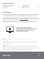
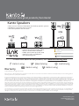
Kanto FMC4 is a full-motion TV wall mount designed to enhance your digital lifestyle. With its ability to extend up to 26" from the wall, swivel up to 135 degrees, and tilt +10° / -5°, you can find the perfect viewing angle for your flat-screen TV up to 100 lbs in weight. The FMC4 also features an adjustable pivot point that allows for side-to-side movement of up to 20", making it ideal for corner mounting or achieving the perfect viewing angle.
Kanto FMC4 is a full-motion TV wall mount designed to enhance your digital lifestyle. With its ability to extend up to 26" from the wall, swivel up to 135 degrees, and tilt +10° / -5°, you can find the perfect viewing angle for your flat-screen TV up to 100 lbs in weight. The FMC4 also features an adjustable pivot point that allows for side-to-side movement of up to 20", making it ideal for corner mounting or achieving the perfect viewing angle.


-
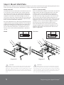
 1
1
-
 2
2
-
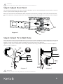
 3
3
-
 4
4
-
 5
5
-
 6
6
-
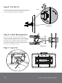 7
7
-
 8
8


Kanto FMC4 is a full-motion TV wall mount designed to enhance your digital lifestyle. With its ability to extend up to 26" from the wall, swivel up to 135 degrees, and tilt +10° / -5°, you can find the perfect viewing angle for your flat-screen TV up to 100 lbs in weight. The FMC4 also features an adjustable pivot point that allows for side-to-side movement of up to 20", making it ideal for corner mounting or achieving the perfect viewing angle.
Ask a question and I''ll find the answer in the document
Finding information in a document is now easier with AI
Related papers
Other documents
-
ElectrIQ CDW12L-BKT Owner's manual
-
Rockville WET-44 PRO Owner's manual
-
 MOR/ryde TV40-002H User manual
-
Rosewill RMS-MF2720 User manual
-
OSD Audio FM-644 Owner's manual
-
Pyle PSTNDW15 User manual
-
-
Mount-It! MI-1121M-CBL User manual
-
Lindy 40877 User manual
-
 Allcam PLB105 Installation guide

