Miller LJ320002A Owner's manual
- Category
- Welding System
- Type
- Owner's manual
This manual is also suitable for

OM-235 848C
2008−06
Processes
Multiprocess Welding
Description
R
XMT 456 CC/CV
(400 Volt Models)
(RoHS)
File: MIG (GMAW)
Visit our website at
www.MillerWelds.com

Miller Electric manufactures a full line
of welders and welding related equipment.
For information on other quality Miller
products, contact your local Miller distributor to receive the latest full
line catalog or individual specification sheets. To locate your nearest
distributor or service agency call 1-800-4-A-Miller, or visit us at
www.MillerWelds.com on the web.
Thank you and congratulations on choosing Miller. Now you can get
the job done and get it done right. We know you don’t have time to do
it any other way.
That’s why when Niels Miller first started building arc welders in 1929,
he made sure his products offered long-lasting value and superior
quality. Like you, his customers couldn’t afford anything less. Miller
products had to be more than the best they could be. They had to be the
best you could buy.
Today, the people that build and sell Miller products continue the
tradition. They’re just as committed to providing equipment and service
that meets the high standards of quality and value established in 1929.
This Owner’s Manual is designed to help you get the most out of your
Miller products. Please take time to read the Safety precautions. They
will help you protect yourself against potential hazards on the worksite.
We’ve made installation and operation quick
and easy. With Miller you can count on years
of reliable service with proper maintenance.
And if for some reason the unit needs repair,
there’s a Troubleshooting section that will
help you figure out what the problem is. The
parts list will then help you to decide the
exact part you may need to fix the problem.
Warranty and service information for your
particular model are also provided.
Miller is the first welding
equipment manufacturer in
the U.S.A. to be registered to
the ISO 9001:2000 Quality
System Standard.
Working as hard as you do
− every power source from
Miller is backed by the most
hassle-free warranty in the
business.
From Miller to You
Mil_Thank 4/05

TABLE OF CONTENTS
SECTION 1 − SAFETY PRECAUTIONS - READ BEFORE USING 1 . . . . . . . . . . . . . . . . . . . . . . . . . . . . . . . . . . .
1-1. Symbol Usage 1 . . . . . . . . . . . . . . . . . . . . . . . . . . . . . . . . . . . . . . . . . . . . . . . . . . . . . . . . . . . . . . . . . . . . . . . .
1-2. Arc Welding Hazards 1 . . . . . . . . . . . . . . . . . . . . . . . . . . . . . . . . . . . . . . . . . . . . . . . . . . . . . . . . . . . . . . . . . .
1-3. Additional Symbols For Installation, Operation, And Maintenance 3 . . . . . . . . . . . . . . . . . . . . . . . . . . . . .
1-4. California Proposition 65 Warnings 4 . . . . . . . . . . . . . . . . . . . . . . . . . . . . . . . . . . . . . . . . . . . . . . . . . . . . . . .
1-5. Principal Safety Standards 4 . . . . . . . . . . . . . . . . . . . . . . . . . . . . . . . . . . . . . . . . . . . . . . . . . . . . . . . . . . . . .
1-6. EMF Information 4 . . . . . . . . . . . . . . . . . . . . . . . . . . . . . . . . . . . . . . . . . . . . . . . . . . . . . . . . . . . . . . . . . . . . . .
SECTION 2 − CONSIGNES DE SÉCURITÉ − LIRE AVANT UTILISATION 5 . . . . . . . . . . . . . . . . . . . . . . . . . . . .
2-1. Symboles utilisés 5 . . . . . . . . . . . . . . . . . . . . . . . . . . . . . . . . . . . . . . . . . . . . . . . . . . . . . . . . . . . . . . . . . . . . .
2-2. Dangers relatifs au soudage à l’arc 5 . . . . . . . . . . . . . . . . . . . . . . . . . . . . . . . . . . . . . . . . . . . . . . . . . . . . . .
2-3. Dangers supplémentaires en relation avec l’installation, le fonctionnement et la maintenance 7 . . . . . .
2-4. Proposition californienne 65 Avertissements 8 . . . . . . . . . . . . . . . . . . . . . . . . . . . . . . . . . . . . . . . . . . . . . . .
2-5. Principales normes de sécurité 9 . . . . . . . . . . . . . . . . . . . . . . . . . . . . . . . . . . . . . . . . . . . . . . . . . . . . . . . . . .
2-6. Information EMF 9 . . . . . . . . . . . . . . . . . . . . . . . . . . . . . . . . . . . . . . . . . . . . . . . . . . . . . . . . . . . . . . . . . . . . . .
SECTION 3 − DEFINITIONS 11 . . . . . . . . . . . . . . . . . . . . . . . . . . . . . . . . . . . . . . . . . . . . . . . . . . . . . . . . . . . . . . . . . . .
3-1. Manufacturer’s Warning Label Definitions 11 . . . . . . . . . . . . . . . . . . . . . . . . . . . . . . . . . . . . . . . . . . . . . . . . .
3-2. WEEE Label 13 . . . . . . . . . . . . . . . . . . . . . . . . . . . . . . . . . . . . . . . . . . . . . . . . . . . . . . . . . . . . . . . . . . . . . . . . .
3-3. Symbols And Definitions 13 . . . . . . . . . . . . . . . . . . . . . . . . . . . . . . . . . . . . . . . . . . . . . . . . . . . . . . . . . . . . . . .
SECTION 4 − INSTALLATION 14 . . . . . . . . . . . . . . . . . . . . . . . . . . . . . . . . . . . . . . . . . . . . . . . . . . . . . . . . . . . . . . . . . .
4-1. Specifications 14 . . . . . . . . . . . . . . . . . . . . . . . . . . . . . . . . . . . . . . . . . . . . . . . . . . . . . . . . . . . . . . . . . . . . . . . .
4-2. Duty Cycle And Overheating 14 . . . . . . . . . . . . . . . . . . . . . . . . . . . . . . . . . . . . . . . . . . . . . . . . . . . . . . . . . . . .
4-3. Volt-Ampere Curves 15 . . . . . . . . . . . . . . . . . . . . . . . . . . . . . . . . . . . . . . . . . . . . . . . . . . . . . . . . . . . . . . . . . . .
4-4. Dimensions And Weight 15 . . . . . . . . . . . . . . . . . . . . . . . . . . . . . . . . . . . . . . . . . . . . . . . . . . . . . . . . . . . . . . . .
4-5. Selecting A Location 16 . . . . . . . . . . . . . . . . . . . . . . . . . . . . . . . . . . . . . . . . . . . . . . . . . . . . . . . . . . . . . . . . . . .
4-6. Connecting To Weld Terminals 16 . . . . . . . . . . . . . . . . . . . . . . . . . . . . . . . . . . . . . . . . . . . . . . . . . . . . . . . . . .
4-7. Weld Output Terminals And Selecting Cable Sizes 17 . . . . . . . . . . . . . . . . . . . . . . . . . . . . . . . . . . . . . . . . . .
4-8. Connecting Weld Output Cables 18 . . . . . . . . . . . . . . . . . . . . . . . . . . . . . . . . . . . . . . . . . . . . . . . . . . . . . . . . .
4-9. Remote 14 Receptacle Information 18 . . . . . . . . . . . . . . . . . . . . . . . . . . . . . . . . . . . . . . . . . . . . . . . . . . . . . . .
4-10. 115 Volts AC Duplex Receptacle 19 . . . . . . . . . . . . . . . . . . . . . . . . . . . . . . . . . . . . . . . . . . . . . . . . . . . . . . . .
4-11. Electrical Service Guide 19 . . . . . . . . . . . . . . . . . . . . . . . . . . . . . . . . . . . . . . . . . . . . . . . . . . . . . . . . . . . . . . . .
4-12. Connecting Input Power 20 . . . . . . . . . . . . . . . . . . . . . . . . . . . . . . . . . . . . . . . . . . . . . . . . . . . . . . . . . . . . . . . .
SECTION 5 − OPERATION 21 . . . . . . . . . . . . . . . . . . . . . . . . . . . . . . . . . . . . . . . . . . . . . . . . . . . . . . . . . . . . . . . . . . . .
5-1. Front Panel Controls 21 . . . . . . . . . . . . . . . . . . . . . . . . . . . . . . . . . . . . . . . . . . . . . . . . . . . . . . . . . . . . . . . . . . .
5-2. Meter Functions 22 . . . . . . . . . . . . . . . . . . . . . . . . . . . . . . . . . . . . . . . . . . . . . . . . . . . . . . . . . . . . . . . . . . . . . .
5-3. Mode Switch Settings 23 . . . . . . . . . . . . . . . . . . . . . . . . . . . . . . . . . . . . . . . . . . . . . . . . . . . . . . . . . . . . . . . . . .
5-4. Lift-Arc TIG Procedure 24 . . . . . . . . . . . . . . . . . . . . . . . . . . . . . . . . . . . . . . . . . . . . . . . . . . . . . . . . . . . . . . . . .
SECTION 6 − MAINTENANCE & TROUBLESHOOTING 25 . . . . . . . . . . . . . . . . . . . . . . . . . . . . . . . . . . . . . . . . . . .
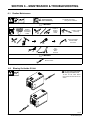
6-1. Routine Maintenance 25 . . . . . . . . . . . . . . . . . . . . . . . . . . . . . . . . . . . . . . . . . . . . . . . . . . . . . . . . . . . . . . . . . .
6-2. Blowing Out Inside Of Unit 25 . . . . . . . . . . . . . . . . . . . . . . . . . . . . . . . . . . . . . . . . . . . . . . . . . . . . . . . . . . . . . .
6-3. Removing Case and Measuring Input Capacitor Voltage 26 . . . . . . . . . . . . . . . . . . . . . . . . . . . . . . . . . . . . .
6-4. Voltmeter/Ammeter Help Displays 27 . . . . . . . . . . . . . . . . . . . . . . . . . . . . . . . . . . . . . . . . . . . . . . . . . . . . . . .
6-5. Troubleshooting 28 . . . . . . . . . . . . . . . . . . . . . . . . . . . . . . . . . . . . . . . . . . . . . . . . . . . . . . . . . . . . . . . . . . . . . .
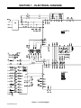
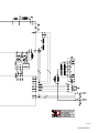
SECTION 7 − ELECTRICAL DIAGRAM 30 . . . . . . . . . . . . . . . . . . . . . . . . . . . . . . . . . . . . . . . . . . . . . . . . . . . . . . . . . .
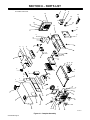
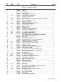
SECTION 8 − PARTS LIST 32 . . . . . . . . . . . . . . . . . . . . . . . . . . . . . . . . . . . . . . . . . . . . . . . . . . . . . . . . . . . . . . . . . . . . .
OPTIONS AND ACCESSORIES
WARRANTY

dec_stat_6/05
Declaration of Conformity for
European Community (CE) Products
. This information is provided for units with CE certification (see rating label on unit).
Manufacturer: European Contact:
Miller Electric Mg. Co. Mr. Danilo Fedolfi,
1635 W. Spencer St. Managing Director
Appleton, WI 54914 USA MILLER Europe S.r.l.
Phone: (920) 734-9821 Via Privata Iseo 6/E
20098 San Giuliano
Milanese, Italy
Phone: 39(02)98290-1
Fax: 39(02)98290203
European Contact Signature:
Declares that the products: XMT
®
456 CC/CV
conforms to the following Directives and Standards:
Directives
Low Voltage Directive: 73/23/EEC
Electromagnetic compatibility Directives: 89/336/EEC, 92/31/EEC
Machinery Directives: 98/37EEC, 91/368/EEC, 92/31/EEC, 133/04, 93/68/EEC
Standards
Arc Welding Equipment − Part 10: Electromagnetic Compatibility (EMC) Requirements.
IEC 60974-10 August 2002
Arc Welding Equipment − Part 1: Welding Power Sources. IEC 60974-1 Ed. 2.1
Degrees of Protection Provided By Enclosures (IP Code): IEC 60529 Ed. 2.1
Insulation Coordination For Equipment Within Low-Voltage Systems:
Part 1: Principles, Requirements And Tests. IEC 60664-1 Ed. 1.1
The product technical file is maintained by the responsible Business Unit(s) located at the manufacturing facility.

OM-235 848 Page 1
SECTION 1 − SAFETY PRECAUTIONS - READ BEFORE USING
som _2007−04
7
Protect yourself and others from injury — read and follow these precautions.
1-1. Symbol Usage
DANGER! − Indicates a hazardous situation which, if
not avoided, will result in death or serious injury. The
possible hazards are shown in the adjoining symbols
or explained in the text.
Indicates a hazardous situation which, if not avoided,
could result in death or serious injury. The possible
hazards are shown in the adjoining symbols or ex-
plained in the text.
NOTICE − Indicates statements not related to personal injury.
. Indicates special instructions.
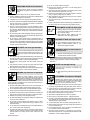
This group of symbols means Warning! Watch Out! ELECTRIC
SHOCK, MOVING PARTS, and HOT PARTS hazards. Consult sym-
bols and related instructions below for necessary actions to avoid the
hazards.
1-2. Arc Welding Hazards
The symbols shown below are used throughout this manual
to call attention to and identify possible hazards. When you
see the symbol, watch out, and follow the related instructions
to avoid the hazard. The safety information given below is
only a summary of the more complete safety information
found in the Safety Standards listed in Section 1-5. Read and
follow all Safety Standards.
Only qualified persons should install, operate, maintain, and
repair this unit.
During operation, keep everybody, especially children, away.
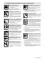
ELECTRIC SHOCK can kill.
Touching live electrical parts can cause fatal shocks
or severe burns. The electrode and work circuit is
electrically live whenever the output is on. The input
power circuit and machine internal circuits are also
live when power is on. In semiautomatic or automatic wire welding, the
wire, wire reel, drive roll housing, and all metal parts touching the
welding wire are electrically live. Incorrectly installed or improperly
grounded equipment is a hazard.
D Do not touch live electrical parts.
D Wear dry, hole-free insulating gloves and body protection.
D Insulate yourself from work and ground using dry insulating mats
or covers big enough to prevent any physical contact with the work
or ground.
D Do not use AC output in damp areas, if movement is confined, or if
there is a danger of falling.
D Use AC output ONLY if required for the welding process.
D If AC output is required, use remote output control if present on
unit.
D Additional safety precautions are required when any of the follow-
ing electrically hazardous conditions are present: in damp
locations or while wearing wet clothing; on metal structures such
as floors, gratings, or scaffolds; when in cramped positions such
as sitting, kneeling, or lying; or when there is a high risk of unavoid-
able or accidental contact with the workpiece or ground. For these
conditions, use the following equipment in order presented: 1) a
semiautomatic DC constant voltage (wire) welder, 2) a DC manual
(stick) welder, or 3) an AC welder with reduced open-circuit volt-
age. In most situations, use of a DC, constant voltage wire welder
is recommended. And, do not work alone!
D Disconnect input power or stop engine before installing or
servicing this equipment. Lockout/tagout input power according to
OSHA 29 CFR 1910.147 (see Safety Standards).
D Properly install and ground this equipment according to its
Owner’s Manual and national, state, and local codes.
D Always verify the supply ground − check and be sure that input
power cord ground wire is properly connected to ground terminal in
disconnect box or that cord plug is connected to a properly
grounded receptacle outlet.
D When making input connections, attach proper grounding conduc-
tor first − double-check connections.
D Keep cords dry, free of oil and grease, and protected from hot metal
and sparks.
D Frequently inspect input power cord for damage or bare wiring −
replace cord immediately if damaged − bare wiring can kill.
D Turn off all equipment when not in use.
D Do not use worn, damaged, undersized, or poorly spliced cables.
D Do not drape cables over your body.
D If earth grounding of the workpiece is required, ground it directly
with a separate cable.
D Do not touch electrode if you are in contact with the work, ground,
or another electrode from a different machine.
D Do not touch electrode holders connected to two welding ma-
chines at the same time since double open-circuit voltage will be
present.
D Use only well-maintained equipment. Repair or replace damaged
parts at once. Maintain unit according to manual.
D Wear a safety harness if working above floor level.
D Keep all panels and covers securely in place.
D Clamp work cable with good metal-to-metal contact to workpiece
or worktable as near the weld as practical.
D Insulate work clamp when not connected to workpiece to prevent
contact with any metal object.
D Do not connect more than one electrode or work cable to any
single weld output terminal.
SIGNIFICANT DC VOLTAGE exists in inverter-type
welding power sources after removal of input
power.
D Turn Off inverter, disconnect input power, and discharge input
capacitors according to instructions in Maintenance Section
before touching any parts.
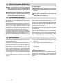
HOT PARTS can cause severe burns.
D Do not touch hot parts bare handed.
D Allow cooling period before working on gun or
torch.
D To handle hot parts, use proper tools and/or
wear heavy, insulated welding gloves and
clothing to prevent burns.

OM-235 848 Page 2
Welding produces fumes and gases. Breathing
these fumes and gases can be hazardous to your
health.
FUMES AND GASES can be hazardous.
D Keep your head out of the fumes. Do not breathe the fumes.
D If inside, ventilate the area and/or use local forced ventilation at the
arc to remove welding fumes and gases.
D If ventilation is poor, wear an approved air-supplied respirator.
D Read and understand the Material Safety Data Sheets (MSDSs)
and the manufacturer’s instructions for metals, consumables,
coatings, cleaners, and degreasers.
D Work in a confined space only if it is well ventilated, or while
wearing an air-supplied respirator. Always have a trained watch-
person nearby. Welding fumes and gases can displace air and
lower the oxygen level causing injury or death. Be sure the breath-
ing air is safe.
D Do not weld in locations near degreasing, cleaning, or spraying op-
erations. The heat and rays of the arc can react with vapors to form
highly toxic and irritating gases.
D Do not weld on coated metals, such as galvanized, lead, or
cadmium plated steel, unless the coating is removed from the weld
area, the area is well ventilated, and while wearing an air-supplied
respirator. The coatings and any metals containing these elements
can give off toxic fumes if welded.
Arc rays from the welding process produce intense
visible and invisible (ultraviolet and infrared) rays
that can burn eyes and skin. Sparks fly off from the
weld.
ARC RAYS can burn eyes and skin.
D Wear an approved welding helmet fitted with a proper shade of fil-
ter lenses to protect your face and eyes when welding or watching
(see ANSI Z49.1 and Z87.1 listed in Safety Standards).
D Wear approved safety glasses with side shields under your
helmet.
D Use protective screens or barriers to protect others from flash,
glare and sparks; warn others not to watch the arc.
D Wear protective clothing made from durable, flame-resistant mate-
rial (leather, heavy cotton, or wool) and foot protection.
Welding on closed containers, such as tanks,
drums, or pipes, can cause them to blow up. Sparks
can fly off from the welding arc. The flying sparks, hot
workpiece, and hot equipment can cause fires and
burns. Accidental contact of electrode to metal objects can cause
sparks, explosion, overheating, or fire. Check and be sure the area is
safe before doing any welding.
WELDING can cause fire or explosion.
D Remove all flammables within 35 ft (10.7 m) of the welding arc. If
this is not possible, tightly cover them with approved covers.
D Do not weld where flying sparks can strike flammable material.
D Protect yourself and others from flying sparks and hot metal.
D Be alert that welding sparks and hot materials from welding can
easily go through small cracks and openings to adjacent areas.
D Watch for fire, and keep a fire extinguisher nearby.
D Be aware that welding on a ceiling, floor, bulkhead, or partition can
cause fire on the hidden side.
D Do not weld on closed containers such as tanks, drums, or pipes,
unless they are properly prepared according to AWS F4.1 (see
Safety Standards).
D Do not weld where the atmosphere may contain flammable dust,
gas, or liquid vapors (such as gasoline).
D Connect work cable to the work as close to the welding area as
practical to prevent welding current from traveling long, possibly
unknown paths and causing electric shock, sparks, and fire
hazards.
D Do not use welder to thaw frozen pipes.
D Remove stick electrode from holder or cut off welding wire at
contact tip when not in use.
D Wear oil-free protective garments such as leather gloves, heavy
shirt, cuffless trousers, high shoes, and a cap.
D Remove any combustibles, such as a butane lighter or matches,
from your person before doing any welding.
D After completion of work, inspect area to ensure it is free of sparks,
glowing embers, and flames.
D Use only correct fuses or circuit breakers. Do not oversize or by-
pass them.
D Follow requirements in OSHA 1910.252 (a) (2) (iv) and NFPA 51B
for hot work and have a fire watcher and extinguisher nearby.
FLYING METAL or DIRT can injure eyes.
D Welding, chipping, wire brushing, and grinding
cause sparks and flying metal. As welds cool,
they can throw off slag.
D Wear approved safety glasses with side
shields even under your welding helmet.
BUILDUP OF GAS can injure or kill.
D Shut off shielding gas supply when not in use.
D Always ventilate confined spaces or use
approved air-supplied respirator.
MAGNETIC FIELDS can affect Implanted
Medical Devices.
D Wearers of Pacemakers and other Implanted
Medical Devices should keep away.
D Implanted Medical Device wearers should consult their doctor
and the device manufacturer before going near arc welding, spot
welding, gouging, plasma arc cutting, or induction heating
operations.
NOISE can damage hearing.
Noise from some processes or equipment can
damage hearing.
D Wear approved ear protection if noise level is
high.
Shielding gas cylinders contain gas under high
pressure. If damaged, a cylinder can explode. Since
gas cylinders are normally part of the welding
process, be sure to treat them carefully.
CYLINDERS can explode if damaged.
D Protect compressed gas cylinders from excessive heat, mechani-
cal shocks, physical damage, slag, open flames, sparks, and arcs.
D Install cylinders in an upright position by securing to a stationary
support or cylinder rack to prevent falling or tipping.
D Keep cylinders away from any welding or other electrical circuits.
D Never drape a welding torch over a gas cylinder.
D Never allow a welding electrode to touch any cylinder.
D Never weld on a pressurized cylinder − explosion will result.
D Use only correct shielding gas cylinders, regulators, hoses, and fit-
tings designed for the specific application; maintain them and
associated parts in good condition.
D Turn face away from valve outlet when opening cylinder valve.
D Keep protective cap in place over valve except when cylinder is in
use or connected for use.
D Use the right equipment, correct procedures, and sufficient num-
ber of persons to lift and move cylinders.
D Read and follow instructions on compressed gas cylinders,
associated equipment, and Compressed Gas Association (CGA)
publication P-1 listed in Safety Standards.

OM-235 848 Page 3
1-3. Additional Symbols For Installation, Operation, And Maintenance
FIRE OR EXPLOSION hazard.
D Do not install or place unit on, over, or near
combustible surfaces.
D Do not install unit near flammables.
D Do not overload building wiring − be sure power supply system is
properly sized, rated, and protected to handle this unit.
FALLING UNIT can cause injury.
D Use lifting eye to lift unit only, NOT running
gear, gas cylinders, or any other accessories.
D Use equipment of adequate capacity to lift and
support unit.
D If using lift forks to move unit, be sure forks are
long enough to extend beyond opposite side of
unit.
OVERUSE can cause OVERHEATING
D Allow cooling period; follow rated duty cycle.
D Reduce current or reduce duty cycle before
starting to weld again.
D Do not block or filter airflow to unit.
FLYING SPARKS can cause injury.
D Wear a face shield to protect eyes and face.
D Shape tungsten electrode only on grinder with
proper guards in a safe location wearing proper
face, hand, and body protection.
D Sparks can cause fires — keep flammables away.
STATIC (ESD) can damage PC boards.
D Put on grounded wrist strap BEFORE handling
boards or parts.
D Use proper static-proof bags and boxes to
store, move, or ship PC boards.
MOVING PARTS can cause injury.
D Keep away from moving parts.
D Keep away from pinch points such as drive
rolls.
WELDING WIRE can cause injury.
D Do not press gun trigger until instructed to do
so.
D Do not point gun toward any part of the body,
other people, or any metal when threading
welding wire.
MOVING PARTS can cause injury.
D Keep away from moving parts such as fans.
D Keep all doors, panels, covers, and guards
closed and securely in place.
D Have only qualified persons remove doors, panels, covers, or
guards for maintenance as necessary.
D Reinstall doors, panels, covers, or guards when maintenance is
finished and before reconnecting input power.
READ INSTRUCTIONS.
D Read Owner’s Manual before using or servic-
ing unit.
D Use only genuine replacement parts from the
manufacturer.
H.F. RADIATION can cause interference.
D High-frequency (H.F.) can interfere with radio
navigation, safety services, computers, and
communications equipment.
D Have only qualified persons familiar with
electronic equipment perform this installation.
D The user is responsible for having a qualified electrician prompt-
ly correct any interference problem resulting from the installa-
tion.
D If notified by the FCC about interference, stop using the
equipment at once.
D Have the installation regularly checked and maintained.
D Keep high-frequency source doors and panels tightly shut, keep
spark gaps at correct setting, and use grounding and shielding to
minimize the possibility of interference.
ARC WELDING can cause interference.
D Electromagnetic energy can interfere with
sensitive electronic equipment such as
computers and computer-driven equipment
such as robots.
D Be sure all equipment in the welding area is
electromagnetically compatible.
D To reduce possible interference, keep weld cables as short as
possible, close together, and down low, such as on the floor.
D Locate welding operation 100 meters from any sensitive elec-
tronic equipment.
D Be sure this welding machine is installed and grounded
according to this manual.
D If interference still occurs, the user must take extra measures
such as moving the welding machine, using shielded cables,
using line filters, or shielding the work area.

OM-235 848 Page 4
1-4. California Proposition 65 Warnings
Welding or cutting equipment produces fumes or gases
which contain chemicals known to the State of California to
cause birth defects and, in some cases, cancer. (California
Health & Safety Code Section 25249.5 et seq.)
Battery posts, terminals and related accessories contain lead
and lead compounds, chemicals known to the State of
California to cause cancer and birth defects or other
reproductive harm. Wash hands after handling.
For Gasoline Engines:
Engine exhaust contains chemicals known to the State of
California to cause cancer, birth defects, or other reproduc-
tive harm.
For Diesel Engines:
Diesel engine exhaust and some of its constituents are
known to the State of California to cause cancer, birth
defects, and other reproductive harm.
1-5. Principal Safety Standards
Safety in Welding, Cutting, and Allied Processes, ANSI Standard Z49.1,
from Global Engineering Documents (phone: 1-877-413-5184, website:
www.global.ihs.com).
Recommended Safe Practices for the Preparation for Welding and Cut-
ting of Containers and Piping, American Welding Society Standard
AWS F4.1, from Global Engineering Documents (phone:
1-877-413-5184, website: www.global.ihs.com).
National Electrical Code, NFPA Standard 70, from National Fire Protec-
tion Association, P.O. Box 9101, Quincy, MA 02269-9101 (phone:
617-770-3000, website: www.nfpa.org and www. sparky.org).
Safe Handling of Compressed Gases in Cylinders, CGA Pamphlet P-1,
from Compressed Gas Association, 4221 Walney Road, 5th Floor,
Chantilly, VA 20151 (phone: 703-788-2700, website:www.cganet.com).
Code for Safety in Welding and Cutting, CSA Standard W117.2, from
Canadian Standards Association, Standards Sales, 5060 Mississauga,
Ontario, Canada L4W 5NS (phone: 800-463-6727 or in Toronto
416-747-4044, website: www.csa-international.org).
Safe Practice For Occupational And Educational Eye And Face Protec-
tion, ANSI Standard Z87.1, from American National Standards Institute,
25 West 43rd Street, New York, NY 10036–8002 (phone:
212-642-4900, website: www.ansi.org).
Standard for Fire Prevention During Welding, Cutting, and Other Hot
Work, NFPA Standard 51B, from National Fire Protection Association,
P.O. Box 9101, Quincy, MA 02269-9101 (phone: 617-770-3000, web-
site: www.nfpa.org.
OSHA, Occupational Safety and Health Standards for General Indus-
try, Title 29, Code of Federal Regulations (CFR), Part 1910, Subpart Q,
and Part 1926, Subpart J, from U.S. Government Printing Office, Super-
intendent of Documents, P.O. Box 371954, Pittsburgh, PA 15250-7954
(phone: 1-866-512-1800) (there are 10 Regional Offices—phone for
Region 5, Chicago, is 312-353-2220, website: www.osha.gov).
1-6. EMF Information
Considerations About Welding And The Effects Of Low Frequency
Electric And Magnetic Fields
Welding current, as it flows through welding cables, will cause electro-
magnetic fields. There has been and still is some concern about such
fields. However, after examining more than 500 studies spanning 17
years of research, a special blue ribbon committee of the National
Research Council concluded that: “The body of evidence, in the
committee’s judgment, has not demonstrated that exposure to power-
frequency electric and magnetic fields is a human-health hazard.”
However, studies are still going forth and evidence continues to be
examined. Until the final conclusions of the research are reached, you
may wish to minimize your exposure to electromagnetic fields when
welding or cutting.
To reduce magnetic fields in the workplace, use the following
procedures:
1. Keep cables close together by twisting or taping them, or using a
cable cover.
2. Arrange cables to one side and away from the operator.
3. Do not coil or drape cables around your body.
4. Keep welding power source and cables as far away from opera-
tor as practical.
5. Connect work clamp to workpiece as close to the weld as possi-
ble.
About Implanted Medical Devices:
Implanted Medical Device wearers should consult their doctor and the
device manufacturer before performing or going near arc welding, spot
welding, gouging, plasma arc cutting, or induction heating operations.
If cleared by your doctor, then following the above procedures is recom-
mended.
Page is loading ...
Page is loading ...
Page is loading ...
Page is loading ...

OM-235 848 Page 9
2-5. Principales normes de sécurité
Safety in Welding, Cutting, and Allied Processes, ANSI Standard Z49.1,
de Global Engineering Documents (téléphone : 1-877-413-5184, site
Internet : www.global.ihs.com).
Recommended Safe Practices for the Preparation for Welding and Cut-
ting of Containers and Piping, American Welding Society Standard
AWS F4.1 de Global Engineering Documents (téléphone :
1-877-413-5184, site Internet : www.global.ihs.com).
National Electrical Code, NFPA Standard 70, de National Fire Protec-
tion Association, P.O. Box 9101, Quincy, MA 02269-9101 (téléphone :
617-770-3000, site Internet : www.nfpa.org).
Safe Handling of Compressed Gases in Cylinders, CGA Pamphlet P-1,
de Compressed Gas Association, 4221 Walney Road, 5th Floor, Chan-
tilly, VA 20151 (téléphone : 703-788-2700, site Internet :
www.cganet.com).
Code for Safety in Welding and Cutting, CSA Standard W117.2, de
Canadian Standards Association, 5060 Mississauga, Ontario, Canada
L4W 5NS (téléphone : 800-463-6727 ou à Toronto 416-747-4044, site
Internet : www.csa-international.org).
Safe Practice For Occupational And Educational Eye And Face Protec-
tion, ANSI Standard Z87.1, de American National Standards Institute,
11 West 43rd Street, New York, NY 10036-8002 (téléphone :
212-642-4900, site Internet : www.ansi.org).
Standard for Fire Prevention During Welding, Cutting, and Other Hot
Work, NFPA Standard 51B, de National Fire Protection Association,
P.O. Box 9101, Quincy, MA 02269-9101 (téléphone : 617-770-3000,
site Internet : www.nfpa.org).
OSHA, Occupational Safety and Health Standards for General Indus-
try, Title 29, Code of Federal Regulations (CFR), Part 1910, Subpart Q,
and Part 1926, Subpart J, de U.S. Government Printing Office, Superin-
tendent of Documents, P.O. Box 371954, Pittsburgh, PA 15250-7954
(téléphone : 1-866-512-1800) (il y a 10 bureaux régionaux−−le télépho-
ne de la région 5, Chicago, est 312-353-2220, site Internet :
www.osha.gov).
2-6. Information EMF
Considérations sur le soudage et les effets de basse fréquence et des
champs magnétiques et électriques.
Le courant de soudage, pendant son passage dans les câbles de sou-
dage, causera des champs électromagnétiques. Il y a eu et il y a encore
un certain souci à propos de tels champs. Cependant, après avoir exa-
miné plus de 500 études qui ont été faites pendant une période de
recherche de 17 ans, un comité spécial ruban bleu du National
Research Council a conclu : « L’accumulation de preuves, suivant le
jugement du comité, n’a pas démontré que l’exposition aux champs
magnétiques et champs électriques à haute fréquence représente un
risque à la santé humaine ». Toutefois, des études sont toujours en
cours et les preuves continuent à être examinées. En attendant que les
conclusions finales de la recherche soient établies, il vous serait
souhaitable de réduire votre exposition aux champs électromagnéti-
ques pendant le soudage ou le coupage.
Pour réduire les champs magnétiques sur le poste de travail, appliquer
les procédures suivantes :
1. Garder les câbles ensemble, les torsader, les scotcher, ou les
recouvrir d’une housse.
2. Disposer les câbles d’un côté et à distance de l’opérateur.
3. Ne pas courber pas et ne pas entourer pas les câbles autour de
votre corps.
4. Garder le poste de soudage et les câbles le plus loin possible de
vous.
5. Connecter la pince sur la pièce aussi près que possible de la
soudure.
En ce qui concerne les implants médicaux :
Les porteurs d’implants doivent d’abord consulter leur médecin avant
de s’approcher des opérations de soudage à l’arc, de soudage par
points, de gougeage, du coupage plasma ou de chauffage par induc-
tion. Si le médecin approuve, il est recommandé de suivre les
procédures précédentes.
Page is loading ...

OM-235 848 Page 11
SECTION 3 − DEFINITIONS
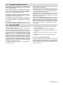
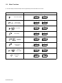
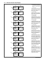
3-1. Manufacturer’s Warning Label Definitions
Warning! Watch Out! There are
possible hazards as shown by the
symbols.
1 Electric shock from welding
electrode or wiring can kill.
1.1 Wear dry insulating gloves.
Do not touch electrode with
bare hand. Do not wear wet or
damaged gloves.
1.2 Protect yourself from electric
shock by insulating yourself
from work and ground.
1.3 Disconnect input plug or
power before working on
machine.
2 Breathing welding fumes can
be hazardous to your health.
2.1 Keep your head out of the
fumes.
2.2 Use forced ventilation or local
exhaust to remove the fumes.
2.3 Use ventilating fan to remove
fumes.
3 Welding sparks can cause
explosion or fire.
3.1 Keep flammables away from
welding. Do not weld near
flammables.
3.2 Welding sparks can cause
fires. Have a fire extinguisher
nearby, and have a
watchperson ready to use it.
3.3 Do not weld on drums or any
closed containers.
4 Arc rays can burn eyes and
injure skin.
4.1 Wear hat and safety glasses.
Use ear protection and button
shirt collar. Use welding
helmet with correct shade of
filter. Wear complete body
protection.
5 Become trained and read the
instructions before working on
the machine or welding.
6 Do not remove or paint over
(cover) the label.
1/96
1 1.1 1.2 1.3
3 3.1 3.2 3.3
4 4.1
+
2 2.1
2.2
+
+
56
+
2.3
S-179 310

OM-235 848 Page 12
> 60 s
V
S-179 190-A
V
V
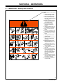
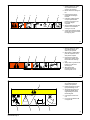
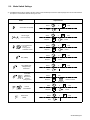
1 Warning! Watch Out! There
are possible hazards as
shown by the symbols.
2 Electric shock from wiring can
kill.
3 Disconnect input plug or
power before working on
machine.
4 Hazardous voltage remains
on input capacitors after
power is turned off. Do not
touch fully charged
capacitors.
5 Always wait 60 seconds after
power is turned off before
working on unit, OR
6 Check input capacitor voltage,
and be sure it is near 0 before
touching any parts.
4/96
1234 5 6
S-179 304-A
1 Warning! Watch Out! There
are possible hazards as
shown by the symbols.
2 When power is applied failed
parts can explode or cause
other parts to explode.
3 Flying pieces of parts can
cause injury. Always wear a
face shield when servicing
unit.
4 Always wear long sleeves and
button your collar when
servicing unit.
5 After taking proper
precautions as shown,
connect power to unit.
4/96
1 23 4 5
S-179 309-A
∠ = <60
°
∠
1 Warning! Watch Out! There
are possible hazards as
shown by the symbols.
2 Falling equipment can cause
injury and damage to unit.
3 Always lift and support unit
using both handles. Keep
angle of lifting device less
than 60 degrees.
4 Use a proper cart to move
unit.
5 Do not use one handle to lift
or support unit.
1/96
1
2345

OM-235 848 Page 13
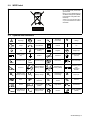
3-2. WEEE Label
Do not discard this product with
general waste.
Reuse or recycle Waste Electrical
and Electronic Equipment (WEEE)
by disposing at a designated collec-
tion facility.
Contact your local recycling office
or your local distributor for further
information.
3-3. Symbols And Definitions
A
Amperage Panel
Alternating
Current (AC)
V
Voltage
Output Circuit Breaker Remote On
Off
Gas Tungsten Arc
Welding
Negative Voltage Input
Direct Current
(DC)
Positive Inductance
Protective Earth
(Ground)
Constant Current Constant Voltage Foot Control Line Connection
Arc Force
Shielded Metal Arc
Welding (SMAW)
Gas Metal Arc
Welding (GMAW)
Three Phase Static
Frequency Con-
verter-
Transformer-
Rectifier
U
0
Rated No Load
Voltage (Average) U
1
Primary Voltage
U
2
Conventional
Load Voltage
X
Duty Cycle
Hz
Hertz
IP
Degree Of
Protection
I
2
Rated Welding
Current
%
Percent
Pulsed
Lift-Arc Trigger
Hold Operation
(GTAW)
Single Phase Three Phase
I
1max
Rated Maximum
Supply Current
I
1eff
Maximum Effective
Supply Current
Increase
Lift-Arc Operation
(GTAW)

OM-235 848 Page 14
SECTION 4 − INSTALLATION
4-1. Specifications
Input
Power
Rated Welding
Output
Amperage
Range
Voltage
Range
Maximum
Open-
Circuit
Voltage DC
Amperes Input
At Rated Load
Output 50 Hz,
Three-Phase
400 V KVA KW
Three
Phase
450 A @ 38 Volts DC,
100% Duty Cycle;
550 A @ 42 Volts DC,
60% Duty Cycle
5 − 600 10 − 38 95 31 21.6 19.4
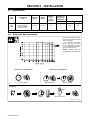
4-2. Duty Cycle And Overheating
Duty Cycle is percentage of 10 min-
utes that unit can weld at rated load
without overheating.
If unit overheats, thermostat(s)
opens, output stops, and cooling
fan runs. Wait fifteen minutes for
unit to cool. Reduce amperage or
duty cycle before welding.
NOTICE − Exceeding duty cycle
can damage unit and void warranty.
Overheating
0
15
A/V
OR
Reduce Duty Cycle
Minutes
duty1 4/95 − SA-181 560
Continuous Welding
100% Duty Cycle At 450 Amperes 60% Duty Cycle At 565 Amperes
6 Minutes Welding 4 Minutes Resting

OM-235 848 Page 15
4-3. Volt-Ampere Curves
Volt-ampere curves show mini-
mum and maximum voltage and
amperage output capabilities of
unit. Curves of other settings fall be-
tween curves shown.
va_curve1 4/95 − SA-181 561 / SA-181 562
CC Modes
CV Modes
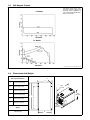
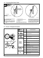
4-4. Dimensions And Weight
Hole Layout Dimensions
15-1/2 in
(394 mm)
28 in
(711 mm)
18 in
(457 mm)
A
B
C
D
F
E
A 14-21/64 in (363.9 mm)
B 20-3/4 in (527.1 mm)
C 23-27/64 in (594.9 mm)
D 24-31/32 in (634.2 mm)
E 12-3/8 in (314.3 mm)
F 9/32 in (7.1 mm) Dia.
Weight
118 lb (53.5 kg)

OM-235 848 Page 16
4-5. Selecting A Location
loc_2 3/96 - 800 611 / 802 260
1 Lifting Forks
Use lifting forks to move unit.
Extend forks beyond opposite side
of unit.
2 Lifting Handles
Use handles to lift unit.
3 Hand Cart
Use cart or similar device to move
unit.
4 Rating Label - Typical
Use rating label to determine input
power needs.
5 Line Disconnect Device
Locate unit near correct input
power supply.
! Special installation may be
required where gasoline or
volatile liquids are present −
see NEC Article 511 or CEC
Section 20.
Movement
3
Location
5
18 in
(460 mm)
18 in
(460 mm)
Tipping
1
OR
2
! Do not move or operate
unit where it could tip.
4
4-6. Connecting To Weld Terminals
! Turn off power before con-
necting to weld output ter-
minals.
1 Positive (+) Weld Output
Terminal
2 Negative (−) Weld Output
Terminal
Connect positive weld cable to
Positive (+) weld terminal and
negative (−) cable to Negative
weld terminal.
Tools Needed:
Ref. 802 260
1
2

OM-235 848 Page 17
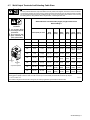
4-7. Weld Output Terminals And Selecting Cable Sizes
! ARC WELDING can cause Electromagnetic Interference.
To reduce possible interference, keep weld cables as short as possible, close together, and down low, such as on the floor.
Locate welding operation 100 meters from any sensitive electronic equipment. Be sure this welding machine is installed
and grounded according to this manual. If interference still occurs, the user must take extra measures such as moving
the welding machine, using shielded cables, using line filters, or shielding the work area.
! Turn off power before
connecting to weld out-
put terminals.
! Do not use worn, dam-
aged, undersized, or
poorly spliced cables.
Weld Output
Terminals
Weld Cable Size** and Total Cable (Copper) Length in Weld Circuit
Not Exceeding***
100 ft (30 m) or Less
150 ft
(45 m)
200 ft
(60 m)
250 ft
(70 m)
300 ft
(90 m)
350 ft
(105 m)
400 ft
(120 m)
Positive
(+)
Negative
(−)
Output Receptacles
100 4 (20) 4 (20) 4 (20) 3 (30) 2 (35) 1 (50) 1/0 (60) 1/0 (60)
150 3 (30) 3 (30) 2 (35) 1 (50) 1/0 (60) 2/0 (70) 3/0 (95) 3/0 (95)
200 3 (30) 2 (35) 1 (50) 1/0 (60) 2/0 (70) 3/0 (95) 4/0 (120) 4/0 (120)
250 2 (35) 1 (50) 1/0 (60) 2/0 (70) 3/0 (95) 4/0 (120)
2 ea. 2/0
(2x70)
2 ea. 2/0
(2x70)
300 1 (50) 1/0 (60) 2/0 (70) 3/0 (95) 4/0 (120)
2 ea. 2/0
(2x70)
2 ea. 3/0
(2x95)
2 ea. 3/0
(2x95)
350 1/0 (60) 2/0 (70) 3/0 (95) 4/0 (120)
2 ea. 2/0
(2x70)
2 ea. 3/0
(2x95)
2 ea. 3/0
(2x95)
2 ea. 4/0
(2x120)
400 1/0 (60) 2/0 (70) 3/0 (95) 4/0 (120)
2 ea. 2/0
(2x70)
2 ea. 3/0
(2x95)
2 ea. 4/0
(2x120)
2 ea. 4/0
(2x120)
500 2/0 (70) 3/0 (95) 4/0 (120)
2 ea. 2/0
(2x70)
2 ea. 3/0
(2x95)
2 ea. 4/0
(2x120)
3 ea. 3/0
(3x95)
3 ea. 3/0
(3x95)
600 3/0 (95) 4/0 (120)
2 ea. 2/0
(2x70)
2 ea. 3/0
(2x95)
2 ea. 4/0
(2x120)
3 ea. 3/0
(3x95)
3 ea. 4/0
(3x120)
3 ea. 4/0
(3x120)
* This chart is a general guideline and may not suit all applications. If cable overheats, use next size larger cable.
**Weld cable size (AWG) is based on either a 4 volts or less drop or a current density of at least 300 circular mils per ampere.
( ) = mm
2
for metric use S-0007-F−
***For distances longer than those shown in this guide, call a factory applications representative at 920-735-4505.

OM-235 848 Page 18
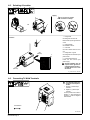
4-8. Connecting Weld Output Cables
803 778-B
! Turn off power before connecting to
weld output terminals.
! Failure to properly connect weld
cables may cause excessive heat
and start a fire, or damage your ma-
chine.
1 Weld Output Terminal
2 Supplied Weld Output Terminal Nut
3 Weld Cable Terminal
4 Copper Bar
Remove supplied nut from weld output ter-
minal. Slide weld cable terminal onto weld
output terminal and secure with nut so that
weld cable terminal is tight against copper
bar. Do not place anything between weld
cable terminal and copper bar. Make
sure that the surfaces of the weld cable
terminal and copper bar are clean.
Tools Needed:
3/4 in (19 mm)
4
2
3
Do not place
anything between
Incorrect Installation
1
weld cable terminal
and copper bar.
4-9. Remote 14 Receptacle Information
Ref. 802 260
AJ
B
K
I
C
L
NH
D
M
G
E
F
Socket* Socket Information
24 VOLTS AC
A 24 volts ac. Protected by circuit breaker CB2.
B Contact closure to A completes 24 volts ac con-
tactor control circuit.
115 VOLTS AC
I 115 volts ac. Protected by circuit breaker CB1.
J Contact closure to I completes 115 volts ac con-
tactor control circuit.
REMOTE
OUTPUT
CONTROL
C Output to remote control; +10 volts dc in MIG
mode.
D Remote control circuit common.
E 0 to +10 volts dc input command signal from re-
mote control.
M Mode select.
N Remote inductance control.
A/V
AMPERAGE
VOLTAGE
F Current feedback; +1 volt dc per 100 amperes.
H Voltage feedback; +1 volt dc per 10 arc volts.
GND
G Circuit common for 24 and 115 volts ac circuits.
K Chassis common.
*The remaining sockets are not used.

OM-235 848 Page 19
4-10. 115 Volts AC Duplex Receptacle
Ref. 801 524-A
1 115 V 7 A AC Receptacle
Power is shared between duplex
receptacle and Remote 14 recep-
tacle (see Section 4-9).
2 Circuit Breaker CB1
3 Circuit Breaker CB2
CB1 protects 115 volts ac portion of
duplex receptacle and Remote 14
receptacle from overload.
CB2 protects 24 volts ac portion of
Remote 14 receptacle from
overload.
Press button to reset breaker.
2 3
1
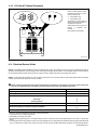
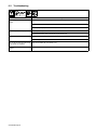
4-11. Electrical Service Guide
NOTICE − INCORRECT INPUT POWER can damage this welding power source. This welding power source requires a CONTINUOUS supply of
input power at rated frequency(+10%) and voltage (+10%). Phase to ground voltage shall not exceed +10% of rated input voltage. Do not use a genera-
tor with automatic idle device (that idles engine when no load is sensed) to supply input power to this welding power source.
NOTICE − Actual input voltage should not be 10% less than minimum and/or 10% more than maximum input voltages listed in table. If actual input
voltage is outside this range, output may not be be available.
Failure to follow these electrical service guide recommendations could create an electric shock or fire hazard. These recommenda-
tions are for a dedicated branch circuit sized for the rated output and duty cycle of the welding power source.
50 Hz Three Phase
Input Voltage 400
Input Amperes At Rated Output 31
Max Recommended Standard Fuse Rating In Amperes
1
Time-Delay
2
35
Normal Operating
3
45
Min Input Conductor Size In AWG
4
10
Max Recommended Input Conductor Length In Feet (Meters)
201
(61)
Min Grounding Conductor Size In AWG
4
10
Reference: 2005 National Electrical Code (NEC) (including article 630)
1 Consult factory for circuit breaker applications.
2 “Time-Delay” fuses are UL class “RK5” .
3 “Normal Operating” (general purpose - no intentional delay) fuses are UL class “K5” (up to and including 60 amp), and UL class “H” ( 65 amp and
above).
4 Conductor data in this section specifies conductor size (excluding flexible cord or cable) between the panelboard and the equipment per NEC Table
310.16. If a flexible cord or cable is used, minimum conductor size may increase. See NEC Table 400.5(A) for flexible cord and cable requirements.

OM-235 848 Page 20
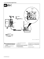
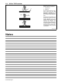
4-12. Connecting Input Power
ssb2.4* 1/94 − 801 523-B / 801 946
Tools Needed:
5/16 in
Input Filter
Board
L1
=GND/PE
! Turn Off welding power source, and
check voltage on input capacitors
according to Section 6-3 before pro-
ceeding.
Check input voltage available at site.
Remove left side panel.
1 Input And Grounding Conductors
See Section 4-11.
Install ring terminals of proper size onto input
conductors for connection to input filter board
terminals (see illustration).
2 Line Disconnect Device
Select type and size of overcurrent protection
using Section 4-11. Connect input and
grounding conductors to a deenergized line
disconnect device.
Reinstall left side panel.
L1
2
L2
L3
1
L2
L3
! Always connect
grounding conductor
first.

OM-235 848 Page 21
SECTION 5 − OPERATION
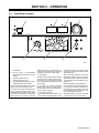
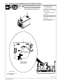
5-1. Front Panel Controls
1 Power Switch
. The fan motor is thermostatically
controlled and only runs when cooling is
needed.
2 Voltmeter (see Section 5-2)
3 Ammeter (see Section 5-2)
4 V/A (Voltage/Amperage) Adjust Control
5 Voltage/Amperage Control Switch
For front panel control, place switch in Panel
position and use the V/A Adjust control.
For remote control, make connections to Re-
mote 14 receptacle, and place switch in Re-
mote position. In most modes, remote control
is a percent of the V/A Adjust control setting.
Value selected on V/A Adjust is maximum
available on remote. In the MIG mode, re-
mote control provides full range of unit output
regardless of V/A Adjust control setting.
6 Mode Switch
The Mode switch setting determines both the
process and output On/Off control (see Sec-
tion 5-3). Source of control (panel or remote)
for the amount of output is selected on the V/A
Control switch.
For Air Carbon Arc (CAC-A) cutting and
gouging, place switch in the Stick position.
For best results, place Inductance/Dig con-
trol in the maximum position.
7 Inductance/Dig Control
Control adjusts Dig when the Stick or CC
mode is selected on the Mode switch. When
set towards minimum, short-circuit amper-
age at low arc voltage is the same as normal
welding amperage.
When set towards maximum, short-circuit
amperage is increased at low arc voltage to
assist with arc starts as well as reduce stick-
ing while welding (see volt-ampere curves in
Section 4-3).
Select setting best suited for application.
Control adjusts inductance when MIG posi-
tion is selected on the Mode switch. Induc-
tance determines the “wetness” of the weld
puddle. When set towards maximum, “wet-
ness” (puddle fluidity) increases.
When Pulsed MIG, or one of the TIG modes
is selected, this control is not functional.
23
4
7
196 445
1
56
Page is loading ...
Page is loading ...
Page is loading ...
Page is loading ...
Page is loading ...
Page is loading ...
Page is loading ...
Page is loading ...
Page is loading ...
Page is loading ...
Page is loading ...
Page is loading ...
Page is loading ...
Page is loading ...
Page is loading ...
-
 1
1
-
 2
2
-
 3
3
-
 4
4
-
 5
5
-
 6
6
-
 7
7
-
 8
8
-
 9
9
-
 10
10
-
 11
11
-
 12
12
-
 13
13
-
 14
14
-
 15
15
-
 16
16
-
 17
17
-
 18
18
-
 19
19
-
 20
20
-
 21
21
-
 22
22
-
 23
23
-
 24
24
-
 25
25
-
 26
26
-
 27
27
-
 28
28
-
 29
29
-
 30
30
-
 31
31
-
 32
32
-
 33
33
-
 34
34
-
 35
35
-
 36
36
-
 37
37
-
 38
38
-
 39
39
-
 40
40


Miller LJ320002A Owner's manual
- Category
- Welding System
- Type
- Owner's manual
- This manual is also suitable for
Ask a question and I''ll find the answer in the document
Finding information in a document is now easier with AI