
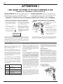
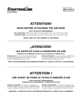
ATTENTION !
LIRE AVANT DE FIXER LE TUYAU D’ARRIVÉE D’AIR
HVLP AIR SUPPLY REQUIREMENTS
EXIGENCES HVLP CONCERNANT L’ALIMENTATION EN AIR
PISTOLET Á PEINTURE:
Une pression à l'admission de
2,07 BAR (30 PSI) donne une pression de 0,69 BAR (10 PSI)
à l’anneau déflecteur. Utilise 0,37 m
3
(13 pi
3
) à la minute.
REMARQUE : UTILISER UN TUYAU D’UN DIAMÈTRE INTÉRIEUR DE 7,94 MM (5/16 PO) AU MINIMUM.
PISTOLET DE RETOUCHE:
Une pression à l'admission de
2,07 BAR (30 PSI) donne une pression de 0,69 BAR (10 PSI)
à l’anneau déflecteur. Utilise 0,23 m
3
(8 pi
3
) à la minute.
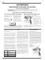
ATTENTION!
READ BEFORE ATTACHING THE AIR HOSE
HVLP AIR SUPPLY REQUIREMENTS
FULL SIZE GUN: 30 PSI inlet pressure provides 10 PSI at the air cap. Consumes 13 CFM.
TOUCHUP GUN: 30 PSI inlet pressure provides 10 PSI at the air cap. Consumes 8 CFM.
NOTE: USE 5/16" OR LARGER I.D. AIR HOSES
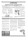
¡ATENCIÓN!
LEA ANTES DE FIJAR LA MANGUERA DE AIRE
REQUISITOS DE SUMINISTRO DE AIRE DE ALTO VOLUMEN BAJA PRESIÓN (HVLP)
PISTOLA HVLP: Una presión de entrada de 30 PSI (libras
por pulgada cuadrada) proporciona 10 PSI en la boquilla.
Consume 13 CFM (pies cúbicos por minuto).
NOTA: UTILICE MANGUERAS CON DIÁMETRO INTERNO DE 7.94 MM (5/16 DE PULG.) O MÁS GRANDE
PISTOLA RE-TOQUE: Una presión de entrada de 30 PSI (libras
por pulgada cuadrada) proporciona 10 PSI en la boquilla.
Consume 8 CFM (pies cúbicos por minuto).
SB-2-610-R1 (4/2018) 1 / 3 www.carlisleft.com
EN
SERVICE MANUAL

ATTENTION!
READ BEFORE ATTACHING THE AIR HOSE
HVLP AIR SUPPLY REQUIREMENTS
FULL SIZE GUN: 30 PSI inlet pressure provides 10 PSI at the air cap. Consumes 13 CFM.
TOUCHUP GUN: 30 PSI inlet pressure provides 10 PSI at the air cap. Consumes 8 CFM.
NOTE: USE 5/16" OR LARGER I.D. AIR HOSES
4. If desired, attach air adjust-
ing valve with gauge and/
or quick disconnect to air
inlet, then attach hose.
5. Spray test and adjust air
pressure, fan size, and
fluid flow as required.
Recommended spray
distance is 6-8 inches.
SET-UP AND ADJUSTMENT INSTRUCTIONS
1. Attach cup to gun and
flush solvent through gun
to remove oils.
2. Tighten packing nut—see
instructions.
3. Fully open fan and fluid
needle controls (turn
counter-clockwise).
Before using this spray gun,
the packing nut should be
adjusted as follows:
1. Tighten packing nut until
fluid needle starts to bind
in the packing.
2. Loosen packing nut just
enough so the fluid needle
moves freely.
PACKING ADJUSTMENT INSTRUCTIONS
AIR CAP
PACKING
NUT
FLUID NEEDLE
FAN CONTROL
FLUID NEEDLE CONTROL
The packing nut is intentionally left loose so the PTFE packing
does not take a "set" before the spray gun is used. This allows
full utilization of the packing.
A failure resulting in injury or damage may be caused by pressure
beyond top of scale, excessive vibration or pressure pulsation,
excessive instrument temperature, corrosion of the pressure con-
taining parts or other misuse of the air adjusting valve with gauge.
A
C
B
D
Spray a test area. Turn the fluid needle
adjusting knob counterclockwise until a
full coat is obtained.
If the finish is too sandy and dry, the
material flow may be too low for the
atomization air pressure being used.
Turn the fluid needle adjusting knob
counterclockwise to increase fluid flow.
If the finish sags, there is too much mate-
rial flowing for the atomization air pressure
being used. Turn the fluid needle adjusting
knob clockwise to decrease fluid flow.
Pattern width can be altered by turn-
ing spreader adjustment valve, either
clockwise to decrease the width or coun-
terclockwise to increase the width.
Adjust inlet air pressure to provide a uni-
form dispersion of atomized paint through-
out the pattern. Keep air pressure as low
as possible to minimize bounce-back and
overspray. Excessive pressure will result in
split spray patterns. Inadequate pressures
will cause heavy centered patterns and
poor atomization.
CLEANING
For routine cleaning, it is not necessary
to remove cup from gun. Remove lid and
properly dispose of any excess paint. Pour
in a small amount of clean solvent. The
amount will vary with different coatings and
solvents. Reinstall lid. Shake cup to wash
down the inside surfaces. Pull trigger to
allow some solvent to be flushed through
gun. Remove lid and pour out dirty solvent.
Add a small amount of clean solvent and
repeat procedure. Wipe exterior of lid with
a clean cloth and clean solvent.
If a paint filter was used in the bottom of
the cup outlet, it should be removed and
cleaned at this time.
To clean air cap and fluid tip, brush exte-
rior with a stiff bristle brush. If necessary
to clean cap holes, use a broom straw or
toothpick if possible. If a wire or hard instru-
ment is used, extreme care must be used to
prevent scratching or burring of the holes
which will cause a distorted spray pattern.
To clean fluid passages, remove excess
material at source, then flush with a suit-
able solvent. Wipe gun exterior with a
solvent dampened cloth. Never completely
immerse in solvent as this is detrimental
to the lubricants and packings.
PREVENTIVE MAINTENANCE
Spray Gun Lubrication
Apply a drop of spray gun lube at trigger
bearing stud and the stem of the air valve.
The shank of the fluid needle where it enters
the packing nut should also be oiled. The
fluid needle packing should be kept soft
and pliable by periodic lubrication. Make
sure the baffle and retaining ring threads
are clean and free of foreign matter. Before
assembling retaining ring to baffle, clean
the threads thoroughly, then add two drops
of spray gun lube to threads. The fluid
needle spring and air valve spring should
be coated with a very light grease, making
sure that any excess grease will not clog
the air passages. For best results, lubricate
the points indicated, daily.
A. Trigger Points
B. Packing
C. Adjusting Valve
D. Baffle/Air Cap Threads
Fluid Tip
Size (mm) Applications
1.0 General purpose, light to medium
viscosity material.
1.3 Top coats.
1.5 Top coats and primer sealers.
1.8 Primers.
EN
SB-2-610-R1 (4/2018)2 / 3www.carlisleft.com

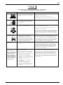
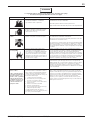
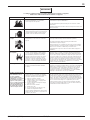
The following hazards may occur during the normal use of this equipment.
Please read the following chart before using this equipment.
Fire
Solvent Spray
Inhaling Toxic Substances
Explosion Hazard -
Incompatible Materials
General Safety
Cumulative Trauma
Disorders ("CTD's")
CTD's, or musculoskeletal
disorders, involve damage
to the hands, wrists,
elbows, shoulders, neck,
and back. Carpal tunnel
syndrome and tendonitis
(such as tennis elbow or
rotator cuff syndrome) are
examples of CTD's.
Solvent and coatings can be highly
flammable or combustible especially when
sprayed.
During use and while cleaning and flushing,
solvents can be forcefully expelled from
fluid and air passages. Some solvents can
cause eye injury.
Certain materials may be harmful if inhaled,
or if there is contact with the skin.
Halogenated hydrocarbon solvents - for
example; methylene chloride and 1,1,1,
- Trichloroethane are not chemically
compatible with the aluminum that might
be used in many system components. The
chemical reaction caused by these solvents
reacting with aluminum can become violent
and lead to an equipment explosion.
Improper operation or maintenance of
equipment.
Use of hand tools may cause cumulative
trauma disorders ("CTD's").
CTD's, when using hand tools, tend to affect
the upper extremities. Factors which may
increase the risk of developing a CTD include:
1. High frequency of the activity.
2. Excessive force, such as gripping,
pinching, or pressing with the hands and
fingers.
3. Extreme or awkward finger, wrist, or arm
positions.
4. Excessive duration of the activity.
5. Tool vibration.
6. Repeated pressure on a body part.
7. Working in cold temperatures.
CTD's can also be caused by such activities
as sewing, golf, tennis, and bowling, to
name a few.
Adequate exhaust must be provided to keep air free of
accumulations of flammable vapors.
Smoking must never be allowed in the spray area.
Fire extinguishing equipment must be present in the spray area.
Wear eye protection.
Follow the requirements of the Safety Data Sheet (SDS) supplied
by your coating material manufacturer.
Adequate exhaust must be provided to keep the air free of
accumulations of toxic materials.
Use a mask or respirator whenever there is a chance of inhaling
sprayed materials. The mask must be compatible with the material
being sprayed and its concentration. Equipment must be as pre-
scribed by an industrial hygienist or safety expert, and be NIOSH
approved.
Guns with stainless steel internal passageways may be used
with these solvents. However, aluminum is widely used in other
spray application equipment - such as material pumps, regula-
tors, valves, and this gun and cup. Check all equipment items
before use and make sure they can also be used safely with these
solvents. Read the label or data sheet for the material you intend
to spray. If in doubt as to whether or not a coating or cleaning
material is compatible, contact your material supplier.
Operators should be given adequate training in the safe use
and maintenance of the equipment (in accordance with the
requirements of NFPA-33, Chapter 15). Users must comply with
all local and national codes of practice and insurance company
requirements governing ventilation, fire precautions, operation,
maintenance, and housekeeping. These are OSHA Sections
1910.94 and 1910.107 and NFPA-33.
Pain, tingling, or numbness in the shoulder, forearm, wrist,
hands, or fingers, especially during the night, may be early
symptoms of a CTD. Do not ignore them. Should you experience
any such symptoms, see a physician immediately. Other early
symptoms may include vague discomfort in the hand, loss of
manual dexterity, and nonspecific pain in the arm. Ignoring early
symptoms and continued repetitive use of the arm, wrist, and
hand can lead to serious disability. Risk is reduced by avoiding or
lessening factors 1-7.
HAZARD CAUSE SAFEGUARDS
EN
SB-2-610-R1 (4/2018) 3 / 3 www.carlisleft.com
Page is loading ...
Page is loading ...
Page is loading ...
Page is loading ...

SB-2-610-R1 (4/2018)8 / 8www.carlisleft.com
For specic warranty information please contact Carlisle Fluid Technologies.
Carlisle Fluid Technologies is a global leader in innovative nishing technologies.
For technical assistance or to locate an authorized distributor,
contact our sales and customer support location.
Region AutomotiveRenishing
Americas Tel: 1-800-445-3988
Fax: 1-800-445-6643
Carlisle Fluid Technologies reserves the right to modify equipment specications without prior notice.
DeVilbiss
®
, Ransburg
®
, ms
®
, BGK
®
, and Binks
®
are registered trademarks of Carlisle Fluid Technologies, Inc.
©2018 Carlisle Fluid Technologies, Inc. All rights reserved.
For the latest information about our products,
visit www.carlisleft.com
29
28
27
6
7-1
7-2 7
8
9
10
11
13
12
14 15 16 +17 18 19 20
26
25
01 30-G1 02 05
21 22 23 22 24 21
03
04
Ref. Part No. Description
01 — AIR CAP w/Ring
02 — FLUID NOZZLE
03 — NUT
04 — GASKET
05 — GUN BODY
06 — HOOK
07 — FAN CONTROL
7-1 — C-CLIP (2 pcs.)
7-2 — O-RING (2 pcs.)
08 — GASKET
09 — O-RING
10 — HOUSING
11 — PAINT NEEDLE
12 — SPRING
13 — KNOB, FLUID CONTROL
14 — GASKET
15 — SCREW
16+17 — VALVE STEM COMPLETE
18 — SPRING
Ref. Part No. Description
19 — O-RING
20 — AIR VALVE NUT
21 — E-RING (2 pcs.)
22 — WASHER (2 pcs.)
23 — TRIGGER
24 — TRIGGER STUD
25 — PLUG
26 — AIR INLET FITTING
27 — FILTER
▲
28 — GASKET for Fitting (2 pcs.)
29 803610 600cc ALUM. CUP & LID
803609 250cc ALUM. CUP & LID
30-G1 — GASKET for Air Cap
31 803591 600cc PUSH-IN LID (Kit of 2 ea.)
803590 250cc PUSH-IN LID (Kit of 2 ea.)
Gun Repair Kit: Full Size (802425) Touchup (802426)
▲
Cup Fitting Gasket Kit: Full Size and Touchup (803615)
Order No. Tip & Needle (Full Size)
803013 StartingLine Tip & Needle (1.3 mm)
803015 StartingLine Tip & Needle (1.5 mm)
803018 StartingLine Tip & Needle (1.8 mm)
803610 600 cc Aluminum Cup and
Push-In Lid (for full size gun)
803609 250 cc Aluminum Cup and
Push-In Lid (for touchup gun)
ACCESSORY ITEMS
31
WARRANTY POLICY
This product is covered by Carlisle Fluid Technologies’ materials and workmanship
limited warranty. The use of any parts or accessories, from a source other than
Carlisle Fluid Technologies, will void all warranties. Failure to reasonably follow
any maintenance guidance provided may invalidate any warranty.
-
 1
1
-
 2
2
-
 3
3
-
 4
4
-
 5
5
-
 6
6
-
 7
7
-
 8
8


Ask a question and I''ll find the answer in the document
Finding information in a document is now easier with AI
in other languages
- français: DeVilbiss 802343 Mode d'emploi
- español: DeVilbiss 802343 Guía del usuario
Related papers
-
 StartingLine StartingLine 802789 User manual
-
 DeVilbiss 802342 Installation guide
-
 DeVilbiss PLUS® Gravity User manual
-
 DeVilbiss PLUS® Pressure Feed User manual
-
 DeVilbiss GTi® Suction Feed User manual
-
 DeVilbiss GTi® Gravity User manual
-
 DeVilbiss GFG-670 PLUS Service Bulletin
-
 DeVilbiss JGA® Pressure Feed User manual
-
Carlisle EGA™ Pressure Feed Owner's manual
-
 DeVilbiss DV1 Clearcoat Spray Gun User manual


Other documents
-
Carlisle TEKNA PRO Owner's manual
-
-
 Binks DUAL GRAVITY GUN SET, FULL SIZE AND TOUCH UP User manual
-
-
-
Kawasaki 840761 User guide
-
 Binks MAG II Spray Gun User manual
-
-
 Binks AA1600M Air Assisted Airless Spray Gun User manual
-


