Page is loading ...

Owner’s Manual
LGR 7000XLi Portable Dehumidifier
Model F412
DRI-EAZ PRODUCTS, INC.
15180 Josh Wilson Road, Burlington, WA 98233
Phone: 800-932-3030 Fax: 360-757-7950 www.dri-eaz.com
The Dri-Eaz® LGR 7000XLi dehumidifier reduces humidity in enclosed environments by
removing water vapor from the air. The 7000XLi is rugged, durable and highly portable, making
it ideal for water damage restoration, structural drying, construction, and other applications
requiring temporary, high-performance dehumidification.
Patents: http://www.LBpatents.com
READ AND SAVE THESE INSTRUCTIONS
SAFETY INSTRUCTIONS
[WARNING! Do not alter or modify your LGR 7000XLi
in any way. Use only replacement parts authorized
by Dri-Eaz Products, Inc. Modifications or use of
unapproved parts could create a hazard and will
void your warranty. Contact your authorized
distributor for assistance.
WARNING! Electric shock hazard, rotating fan, hot
surface hazards. Unplug unit before opening cover
for cleaning or servicing. Unit must be grounded.
• Inspect the power cord before use. If cord is
damaged, do not use. Always grasp the plug (not
the cord) to unplug.
• Insert three-prong plug on power cord into a
matching electrically grounded outlet. Do not use
adapter. Never cut off third prong. Do not use an
extension cord.
• The unit must be operated on a 115V/60 Hz circuit
protected by a Ground Fault Circuit Interrupter
(GFCI) device.
• Keep motor and wiring dry.
• Do not attempt to repair the unit. For Authorized
Service Centers, call Dri–Eaz at 800-932-3030.
BEFORE YOU BEGIN
Warranty registration
Visit warranty.drieaz.com to register your purchase.
Registration allows us to better assist you with using,
maintaining or servicing your equipment and to contact
you in case we have important safety information
concerning your Dri-Eaz product. If you determine
service is required, have your equipment model, serial
number and original proof of purchase available and call
your distributor for assistance with obtaining a return
material authorization (RMA).
CONTENTS GUIDE
OPERATIONS
Parts identification .......................................... 2
Positioning a dehumidifier ............................. 2
Operating your dehumidifier .......................... 2
Control Panel Guide ........................................ 3
At the end of the job ........................................ 4
Setting humidistat mode ................................. 4
MAINTENANCE
Maintenance schedule .................................... 6
Cleaning the coils and block .......................... 6
Cleaning the pump valve .............................. 11
Inspecting the Control Panel ........................ 17
Error messages ............................................. 19
Troubleshooting ............................................ 20
WARNING
07-01776F 2015-02 F412 (115V) Warranty 07-00420 1 Dri-Eaz Products, Inc.

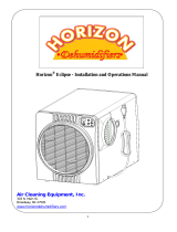
PARTS IDENTIFICATION
OPERATING YOUR DEHUMIDIFIER
Set unit upright
NOTICE: Transporting or storing the unit in a
horizontal position is not recommended. When the
machine is placed in a horizontal position, the oil
from the compressor can flow into the refrigerant
coils and reduce the ability of the dehumidifier to
function and possibly damage the unit. If the unit
has been placed in a horizontal position, set it
upright and let it stand for at least 30 minutes before
turning it on.
Positioning a Dehumidifier
For best results, operate your dehumidifiers in an
enclosed area. Close all doors and windows that open to
the outside to maximize the unit’s water removal
efficiency. Place your dehumidifier away from
obstructions, and keep it away from anything that could
block airflow into and out of the unit. For more
information about creating an optimum drying
environment, contact Dri-Eaz at 800-932-3030.
Power cord socket.
Product label and
serial number.
FIG. A: FRONT
FIG. B: REAR
Humid air inlet.
3M™ HAF filter.
Molded pocket
for cord storage.
Process
(dehumidified) air
outlet. May be used
with standard 12 in.
rigid or layflat
ducting.
FIG. C: POWER
ATTACHMENT POINT
Back panel. Remove to
access the pump.
Integrated handle.
Folds for storage.
Drain hose
pocket.
Control panel.
Drain hose
outlet.
07-01776F 2015-02 F412 (115V) Warranty 07-00420 2 Dri-Eaz Products, Inc.

CONTROL PANEL
ON/OFF
DISPLAY
DISPLAY
MENU
MENU
SELECTION /
UP KEY
PURGE PUMP
Set up drain hose
The 7000XLi condensate pump connects to a plastic
drainage hose that is located in the pocket on the side of
the unit. This hose is equipped with a quick-connect
fitting for quick attachment to the provided 40 ft. (12 m)
drain hose. Unwrap the entire hose and place the
unattached end in a sink, drain, bucket or outdoors –
anywhere that water can drain out safely. If you use a
bucket or other container for water collection, check it
regularly to prevent overflows.
NOTICE: Uncoil and straighten the entire drain hose. Do
not leave any part of the hose coiled on the unit and do
not place the end of the hose higher than 20 ft. (6 m)
above the bottom of the unit. Also check for kinks or
other obstructions that might restrict the flow of water.
Obstructions may cause a water backup and result in
overflows.
Plug in electrical cord
The 7000XLi dehumidifier should be plugged into a
GFCI-protected 115 volt outlet rated for at least 15
amps.
Remove the cord from its storage pocket and uncoil it.
Always plug the cord firmly into the unit first, and then
plug the other end into a suitable outlet.
Turn the unit on
The control panel on the 7000XLi dehumidifier has a
display and a touchpad with four keys. Press the
ON/OFF to turn the unit on.
Startup display and normal display modes
When unit is first plugged in to AC power, the control
panel display will briefly cycle through a series of
readouts. This is part of the unit’s self-diagnosis
procedure and no user intervention is required.
Once the self-diagnosis is complete, the display will
switch to normal display mode.
UNIT ON 00 HRS
INLET 00°C / INLET 00%
The first line of the display shows the total number of
hours the unit has been in operation. This value may be
reset to zero to track job hours (see “Job Hours Reset”
below). The second line of the display alternates
between inlet temperature and inlet humidity.
User Settings Menu
A number of settings may be changed by the user.
System information can also be displayed. These items
are accessed by pressing
DISPLAY MENU. Each
press of the key will display the next parameter. When
you reach the parameter you wish to adjust, press
MENU SELECTION to increase the value. Press
DISPLAY MENU again to accept the setting and re-start
the display cycle. If no keys are selected for 20 seconds
the display will automatically reset and return to the
normal display mode.
Note that only menu items followed by a greater-than
symbol ( > ) may be adjusted.
All settings and modes are discussed in detail in Control
Panel Guide, p. 3.
Error messages
If the 7000XLi onboard diagnostics discover a problem,
the unit will display an error message. See “Error
Messages,” p. 19, for an explanation of each message.
Control Panel Guide
ON/OFF. Press to turn the unit on or off. When the
machine is turned on, the display normally reads
PLEASE WAIT COMP. DELAY and performs a numeral
countdown from a maximum of 60 seconds to 0. This
delay allows time for refrigerant pressures to equalize for
easier starting. Once the unit completes the compressor
delay, the display shows UNIT ON XX HRS and cycles
between INLET XX°F and INLET XX%. NOTE: If no
compressor delay countdown is displayed, a delay is not
necessary and the machine will begin operation
immediately.
DISPLAY MENU. Press to cycle through the display
of additional dehumidifier conditions and User Settings.
To return to the main menu, press the ON/OFF key
once.
MENU SELECTION. Press to change the values of
the "User Defined" settings. The MENU SELECTION
key acts as the UP key for adjusting the setpoint for
ON/OFF
Press and release to turn unit on
or off.
DISPLAY MENU
Press to select next item in menu.
Menu item will show in display.
MENU SELECTION /
UP KEY
Press to toggle or select values in
menu displayed.
PURGE PUMP
Press and release to start purge.
Display will count down seconds
remaining until purge is complete.
07-01776F 2015-02 F412 (115V) Warranty 07-00420 3 Dri-Eaz Products, Inc.

Humidistat mode operation. See User Settings Menu
(below) for details.
PURGE. Press to empty water from the condensate
pump reservoir. The display will read PUMP PURGING
with a numeral countdown. NOTE: During normal
operation, the pump purges automatically every six
minutes, or whenever the reservoir is full.
Changing settings and viewing system information
A number of settings may be changed by the user.
System information is also available. These items are
accessed by pressing
DISPLAY MENU. Each press
of the key will display the next parameter (see list
below). When you reach the parameter you wish to
adjust, press
MENU SELECTION to increase the
value. Press
DISPLAY MENU again to accept the
setting and re-start the display cycle. If no keys are
selected for 20 seconds the display will automatically
reset and return to the normal display mode.
Note that only menu items followed by a greater-than
symbol ( > ) may be adjusted.
JOB HOURS
RESET? >
Press MENU SELECTION to reset hours to zero.
NOTE: When in Humidistat mode, the unit will display
HUMIDISTAT on the top line during normal operation
rather than JOB HOURS.
LIFE HOURS
00 HRS
Shows total unit operating hours. Value cannot be
modified.
INLET OUTLET
00° 00% 00° 00%
Shows current temperature and RH of inlet and outlet.
Humidistat Mode
HUMIDISTAT MODE
ON/OFF >
In ON mode, unit will maintain the humidistat setpoint
(see below). Press MENU SELECTION to toggle
between ON and OFF. NOTE: When in Humidistat
mode, the unit will display HUMIDISTAT on the top line
during normal operation rather than JOB HOURS.
HUMIDISTAT
SETPOINT 00% >
Sets humidity level when unit is in Humidistat Mode.
Press MENU SELECTION to change RH value. Each
press of the button increases the setting by 5%
increments, cycling through 90%RH and starting again
at 30%RH.
TEMP UNITS
F° >
Shows current temperature scale. Press MENU
SELECTION to select Fahrenheit or Centigrade scale.
LANGUAGE
ENGLISH >
Shows current display panel language. Press MENU
SELECTION to select Spanish, German, French or
English.
COIL TEMP
00°F
Displays the cold (evaporator) coil temperature.
SENSOR ID >
00000000
This function is not used on the 7000XLi.
COMPRSSR CURRENT
0.0 A
Shows compressor current draw in amps.
AT THE END OF THE JOB
To reduce the possibility of drips when moving the unit,
follow these additional steps to ensure that all water is
removed from the unit.
NOTICE: To ensure the condensate tank empties
completely while purging, make sure the unit is set fully
upright.
1. If the unit is in a defrost cycle, wait until the unit has
returned to normal operating mode before proceeding.
To check, review the control panel. The control panel will
show one of the following:
Defrost in progress:
UNIT ON 00 HRS
DEFROST CYCLE
Normal Display:
UNIT ON 00 HRS
INLET XX° F
Wait until the control shows the normal display before
proceeding.
2. Gently rock the upright machine on its wheels to
ensure any water remaining on interior surfaces falls into
the sump area.
3. Press the PURGE key. When the purge cycle is
complete, turn the unit off.
4. Remove the external drain hose, drain it carefully, and
return it to the pocket provided on the side of the unit.
5. Unplug power cord from power supply and from base
of the machine, coil neatly, and return it to the coil
storage pocket (see Fig. A).
07-01776F 2015-02 F412 (115V) Warranty 07-00420 4 Dri-Eaz Products, Inc.

TRANSPORTATION AND STORAGE
NOTICE: Handle the unit carefully. Do not drop, throw,
or place the unit where it could fall. Rough treatment can
damage this equipment and may create a hazardous
condition or void warranty.
• Do not expose the control panel to moisture, snow
or rain.
• Store and transport securely to avoid any damaging
impact to internal parts.
• Secure during transport to prevent sliding and
possible injury to vehicle occupants.
Important
Do not store or transport the unit in a horizontal position
(front, sides, or back). This will help to prevent
condensate escaping from the unit unit or flowing into
areas outside the condensate management system.
Special tip for transporting on stairs:
Before transporting unit on stairs, follow these additional
steps to ensure that all water is removed from the unit:
1. Turn the unit off after a defrost cycle has been
completed. Gently rock the upright machine on its
wheels to ensure any water remaining on interior
surfaces falls into the sump area.
2. Press the PURGE key. When the purge cycle is
complete, turn the unit off.
3. Remove the external drain hose, drain it carefully, and
return it to the pocket provided on the side of the unit.
4. IMPORTANT: Remove power cord from base of
unit, coil it neatly, and place it in the cord storage
pocket. This will prevent the cord from catching on
the stairs and possibly damaging the cord.
07-01776F 2015-02 F412 (115V) Warranty 07-00420 5 Dri-Eaz Products, Inc.

⅜ in. rear panel
fasteners (×6)
⅜ in. cover
fasteners
(×2)
Pump location
FIG. D: PARTS DIAGRAM
Heat exchange
block.
HAF filter
Rear panel
Condenser (hot) coil
Evaporator (cold) coil
Cover
Electrical box.
Control
panel
⅜ in. rear panel
base plate fasteners
(×5, not shown)
⅜ in. rear
panel
fasteners (×6)
Sensor chip. Lead cable
(not shown) is attached to
back of control panel.
07-01776F 2015-02 F412 (115V) Warranty 07-00420 6 Dri-Eaz Products, Inc.

MAINTENANCE SCHEDULE
WARNING! ELECTRIC SHOCK HAZARD. Unplug the
dehumidifier before performing any maintenance.
WARNING: Risk of dust and contaminants exposure.
Use of respirator mask and gloves is recommended. If
unit has been exposed to potentially dangerous
contaminants, clean thoroughly and sanitize before
reuse.
NOTICE: The unit is fitted with sensitive electronic
sensors. Protect the sensors and their lead wires from
damage and do not expose them to water or cleaning
solution.
The following tools and supplies are needed to
complete the maintenance procedures described in
this manual:
Philips screwdriver
Flat blade screwdriver
Needle-nose pliers
9
∕
16
in. wrench
3
∕
8
in. nutdriver or socket
5
∕
16
in. socket (to remove pump)
6 in. socket extension
Ratchet wrench
Cleaning cloths
HEPA vacuum cleaner with soft brush nozzle and
crevice nozzle.
Recommended
Cordless drill, small knife, small-jaw pliers, coil
cleaning solution, Rotomolded housing cleaning
solution
Before each use
Inspect the electrical cord for damage. Look for
fraying, cuts, etc. Replace the cord if you find any
damage.
Inspect, vacuum or replace filter. The 3M™ HAF
(High Airflow) filter may be vacuumed clean and
reused up to three times before replacement. Use a
HEPA vacuum and brush tool to remove any dust or
debris. Do not use compressed air or expose the filter to
any liquids, as may damage the filter.
NOTICE: Replace used filters only with a new HAF filter
(Dri-Eaz part no. F368). Other filter types do not provide
adequate filtration or airflow. Be sure to install the new
filter in the correct orientation. See “Installing the HAF
Filter,” p. 8. See also “About HAF Filters,” below.
Monthly
Inspect coils and heat exchange block. Clean when
dust accumulation is visible. In normal use, dust can
accumulate and can restrict airflow, reducing
performance and causing the unit to overheat. See
“Cleaning Coils and Heat Exchange Block,” p. 6.
To maintain appearance, wipe interior and exterior
surfaces with a damp cloth. For deep cleaning and a
lasting, protective shine, use Dri-Eaz MicroGuard
Cleaner and MicroGuard Protectant, available from Dri-
Eaz, or a similar automotive interior treatment.
As Needed
Clean Pump Check Valve and Basin. If the unit
displays the message “ER9 PUMP BLOCKED CHECK
PUMP & HOSE”, the pump check valve and pump basin
may need to be cleaned. This requires removal of the
back cover. For instructions, see “Inspecting and
Cleaning the Pump,” p. 11.
Clean coils and heat exchange block. Inspect the
horizontal evaporator (cold) coil with the back cover
removed. If excessive dust and debris is present,
vacuum thoroughly and/or clean with coil cleaner. See
“Cleaning Coils and Heat Exchange Block,” p. 6.
CLEANING THE COILS AND THE HEAT
EXCHANGE BLOCK
To help keep the unit operating efficiently, keep the coils
and the air-to-air heat exchange block clean, and
periodically remove any accumulated dust and debris
from interior surfaces.
ABOUT 3M™ HAF FILTERS FROM
HAF filters from 3M provide superior particle retention, resist microbial growth on filter surfaces and allow for maximum
airflow throughout the filter loading cycle. Follow these guidelines to ensure maximum protection for equipment,
technicians and the job site:
Replace the HAF filter whenever it has been vacuumed clean and reused three times. HAF filters lose their effectiveness after
three uses.
Replace the HAF filter whenever it has been used on a mold remediation job or otherwise exposed to potentially dangerous
contaminants. Continued use of a contaminated filter risks the spread of contamination.
Do not wash or apply any liquids to the HAF filter. Exposure to liquids will reduce the effectiveness of the electrostatic material.
Do not operate without the HAF filter in place. Do not operate the unit with any other filter type. Incorrect filtration will reduce
unit efficiency and can cause damage to the unit.
Do not operate the unit when excessive dust or airborne particles are present. The high volumes of particulates present during
sanding, spray painting, or similar operations can clog the unit and cause damage.
07-01776F 2015-02 F412 (115V) Warranty 07-00420 7 Dri-Eaz Products, Inc.

Installing the HAF filter
To protect your HAF Filter from damage, make sure you insert the filter in the correct orientation.
CORRECT.
Filter plies are in
line with direction
of insertion.
INCORRECT.
Filter plies are set
90 to direction of
insertion.
Subsequent
removal may pull
apart plies and
damage the filter.
Disassembling the unit to clean coils and the heat exchange block
WARNING: Unplug unit before servicing.
WARNING: Risk of dust and contaminants exposure. Use of respirator mask and gloves is recommended. If unit has
been exposed to potentially dangerous contaminants, clean thoroughly and sanitize before reuse.
NOTICE: The unit is fitted with sensitive electronic sensors. Protect the sensors and their lead wires from damage and do
not expose them to water or cleaning solution.
Before proceeding, remove pump hose at quick-disconnect.
Remove
the four
3
∕
8
in.
cover
bolts
shown:
07-01776F 2015-02 F412 (115V) Warranty 07-00420 8 Dri-Eaz Products, Inc.

Lift off front cover and set aside.
Disconnect the sensor chip assembly from the block.
Gently lift the chip and the mounting post together out of the
block.
NOTICE! The sensor chip assembly is fragile. Handle
with care at all times. To avoid damaging the sensor with
a static electricity discharge, do not touch the sensor
circuitry, and do not place any tape or other material in
contact with the sensor circuitry.
Lift the heat exchange block straight upward off the base.
Note orientation of block for reassembly.
Inspect the heat exchange block carefully. If dust is
present, use compressed air or a HEPA-filtered vacuum
cleaner to gently clear the channels of the block.
07-01776F 2015-02 F412 (115V) Warranty 07-00420 9 Dri-Eaz Products, Inc.

Inspect the vertical condenser (hot) coil. If dust is present,
vacuum or use compressed air on both sides of the coil until it
is clean. Take care not to bend or damage the fins. Vacuum
the outside (shown) and inside surface of the vertical coil.
NOTICE: Do not use coil cleaning solution on the vertical
condenser coil. The solution may drip on to sensitive internal
components and damage them.
The horizontal evaporator (cold) coil (not shown) should
also be vacuumed. For more thorough cleaning, remove the
back cover and use coil cleaner.
Clean the horizontal evaporator (cold) coil. Use a
vacuum or condenser coil cleaner. If using the coil cleaner,
use a small container to capture runoff from the drain basin.
Note: Use Dri-Eaz Coil Cleaner only.
CAUTION: Be sure to thoroughly flush coil cleaner from
coils to avoid damaging the pump and/or pump valve.
Reinstalling the Heat Block and Top Cover
NOTICE: Be sure housing bolts are properly threaded before tightening. Do not overtighten. Do not use a power
tool!
Reinstall the heat exchange block. Be sure to position it in
the original orientation.
Carefully reseat the heat exchange block. Make sure that
the block is flush against the base and vertical condenser (hot)
coil,
Make sure the top of the block is flush with the top of the
condenser coil.
07-01776F 2015-02 F412 (115V) Warranty 07-00420 10 Dri-Eaz Products, Inc.

Replace the sensor chip assembly in to the heat exchange
block.
NOTICE! The sensor chip assembly is fragile. Handle with
care at all times. To avoid potentially damaging the
sensor with a static electricity discharge, do not touch the
sensor circuitry and do not place any tape or other
material in contact with the sensor circuitry.
Slide the top cover straight down into place. Make sure the
foam rubber seal strips are in place and are not kinked or
folded.
Replace the front cover. Insert and tighten the front cover
3
∕
8
in. bolts by hand. After they are hand tight, install and
tighten the two back cover bolts.
NOTICE: Be sure housing bolts are properly threaded before tightening. Do not overtighten. Do not use a power
tool!
The unit is now ready for use.
INSPECTING AND CLEANING THE PUMP CHECK VALVE
Remove the five base plate
3
∕
8
in. bolts. For easier access
to these bolts, lay the unit on its back.
NOTICE: Do not place unit on its front, as this might
cause any residual water to drip into sensitive electronic
components.
Remove the front cover as described under “To
disassemble the unit for cleaning coils and heat exchange
block,” p. 8.
07-01776F 2015-02 F412 (115V) Warranty 07-00420 11 Dri-Eaz Products, Inc.

Stand the unit upright and remove the front cover as
described under “To disassemble the unit for cleaning coils
and heat exchange block,” p. 8.
Now remove the four rear panel
3
∕
8
in. bolts.
Tip the top of the rear panel away from the unit and lay
it flat in front of the unit. It is not necessary to disconnect
the wire harness from the rear panel or from the electrical
box.
Clean and inspect the the pump check valve. First, use
needle-nosed pliers to remove the pumpout hose from the
barbed fitting on the pump. Tuck the hose inside the back
cover housing.
07-01776F 2015-02 F412 (115V) Warranty 07-00420 12 Dri-Eaz Products, Inc.

Remove the two
5
∕
16
in. bolts securing the pump mounting
bracket.
Slide the pump and pump bracket assembly out of the
pump well. It is not necessary to disconnect any electrical
cables.
When the pump is free of the housing, rotate it upward and
out of the pump well to more easily access the check valve.
NOTICE: Take care not to bend or damage the
“marshmallow” float assembly.
Clean and inspect the check valve. Using a
9
∕
16
in wrench,
unthread the check valve fitting and remove it from the
pump.
Using small-jawed pliers, carefully remove the valve
compression fitting and the “duckbill” valve.
07-01776F 2015-02 F412 (115V) Warranty 07-00420 13 Dri-Eaz Products, Inc.

Rinse all three items in clean water.
Reassemble the check valve components in the sequence
shown.
Thread the check valve assembly back into pump outlet.
Inspect the float and pump switch for proper operation.
Ensure the float arm moves freely and that the switch
operates. Take care not to bend or damage the float arm.
Using a Philips screwdriver, remove the five screws
from the impeller plate.
07-01776F 2015-02 F412 (115V) Warranty 07-00420 14 Dri-Eaz Products, Inc.

Turn pump over and slide impeller assembly out. Take
care to catch any parts that may be loose and fall out.
Inspect impeller, magnetic shaft, and flapper valve for
damage. Wipe all surfaces clean with a soft cloth.
Reassemble pump following the steps above in reverse
order.
Make sure flapper valve is properly seated and oriented
in the correct direction.
Tip: Slide the main pump body over the pump base and
ensure that the pump base is fully inserted into the
pump housing before turning the pump over to install
the mounting screws. Failure to do so may result in the
“flapper” becoming dislodged and limiting the pump’s
performance or preventing the impeller from turning.
NOTICE: Make sure O-ring is properly seated before
tightening impeller cover. Do not overtighten cover screws.
07-01776F 2015-02 F412 (115V) Warranty 07-00420 15 Dri-Eaz Products, Inc.

Reassembling pump and back cover
Wipe out the pump basin with a clean, dry cloth.
Reinstall pump. Slide pump and pump bracket back into
place.
Ensure that the two holes in the bracket, the rotomolded
housing and the pump basin are properly aligned before
inserting and starting the bolts by hand.
Reinstall the two
5
∕
16
in. bolts securing the pump mounting
bracket. Do not overtighten.
Reinstall drain hose on to pump outlet.
Tip back cover into place. Ensure that the sealing strips are
properly aligned and free of kinks.
Replace four bolts on the lower half of the back cover. Leave bolts snug but not tight. Now place the unit on its
back.
NOTICE: Be sure housing bolts are properly threaded before tightening. Do not overtighten. Do not use a power
tool!
Reinstall five bottom plate
3
∕
8
in. bolts.
Now set the unit upright and tighten the four back cover bolts.
Reinstall the top cover. See “Reinstalling the Heat Block and Top Cover” beginning on p. 10.
TIP: Tighten cover bolts in increments from the bottom upward to create the best seal. As you tighten, check for proper
alignment and ensure that all seals are in place and free of kinks.
The unit is now ready for use.
07-01776F 2015-02 F412 (115V) Warranty 07-00420 16 Dri-Eaz Products, Inc.

DRAINING/WINTERIZING
The unit is equipped with a drain to allow removal of any water
that might remain in the unit after operating the purge function.
Draining the unit is especially important when the unit might be
exposed to freezing conditions during storage or transport.
After placing a catch basin under the plug, use a
3
∕
8
in. wrench
to remove the drain plug located in the lower right corner of the
rear panel.
Tip: With the drain plug removed, gently shake the unit
and then tip the unit back and to the right. This will allow
for more complete removal of any water that has collected
in the rear panel.
Once any water has drained out, replace the plug. Tighten until
snug. Do not overtighten.
INSPECTING THE CONTROL PANEL
Using a Philips screwdriver, remove the four baseplate
retaining screws.
Carefully lift out the control panel. The sensor connections
are located on the underside of the panel.
The sensor connections are labeled “OUT T” (outlet
temperature sensor) and “DEFR” (defrost sensor).
Note that the DEFR cable is marked with silver paint. Make
sure each cable is connected in the correct location and that
they are firmly seated.
07-01776F 2015-02 F412 (115V) Warranty 07-00420 17 Dri-Eaz Products, Inc.

The DIP switch is located in the center of the panel. Do not
change the DIP settings unless instructed by qualified service
personnel to do so.
NOTICE! The control panel circuit board contains sensitive
electronic components. Handle with care at all times. To
avoid damaging the circuit board with a static electricity
discharge, do not touch the circuitry, and do not place any
tape or other material in contact with the circuit board.
When inspection is complete, replace the controller in the housing and tighten the screws. Do not overtighten.
07-01776F 2015-02 F412 (115V) Warranty 07-00420 18 Dri-Eaz Products, Inc.

ERROR MESSAGES
The LGR 7000XLi control system constantly monitors internal operating conditions. If the system detects an problem, it
will produce an error (“ER”) message indicating the problem. If the display shows an ER message, first unplug the unit
and then plug it back in. This will usually reset the electronics, and the unit will begin operating normally. If the error
message reappears, refer to the explanation and solution shown below. If this still does not fix the problem, contact your
local authorized service center or call the Dri-Eaz Service Department at 800-932-3030.
NOTE: The message “POWER FAILURE” is not a system error. When this message is displayed, it indicates that
power to unit was interrupted and then restored. To clear the message, press the MENU SELECTION key.
CONTROL PANEL
MESSAGE
EXPLANATION AND SOLUTION
ER1 CONTACT SERVICE
CENTER
Voltage error. Confirm that unit is connected to a suitable AC power supply and that the
circuit is not overloaded. If supply is correct, the electronic control panel may require
replacement. If error persists, contact service.
ER2 CONTACT SERVICE
CENTER
Control panel error. The electronic control panel may require replacement. If error
persists, contact service.
ER3 CONTACT SERVICE
CENTER
Unit in defrost too long. Check defrost sensor cable for proper connection. See
“Inspecting the Control Panel,” p. 17, for instructions. If error persists, sensor assembly
may require replacement. Contact service.
ER4 √ DEFROST SENSOR
CONNECT
– alternate message –
ER4 √ OUTLET SENSOR
CONNECT
Sensor error. Check defrost sensor cable for proper connection. See “Inspecting the
Control Panel,” p. 17, for instructions. If error persists, sensor assembly may require
replacement. Contact service.
ER5 √ SENSOR
CONNECTION ON BD
Low voltage board error. Check outlet temp sensor cable for proper connection. See
“Inspecting the Control Panel,” p. 17, for instructions. If error persists, sensor assembly
may require replacement. Contact service.
ER6 CONTACT
SERVICE CENTER
High voltage error. The high voltage board may require replacement. If error persists,
contact service.
ER7 INVALID
MODEL SETTING
Control board DIP switch settings or firmware version may be incorrect. If error persists,
contact service. Service may ask you to verify DIP switch settings. See “Inspecting the
Control Panel,” p. 17, for instructions.
ER8 BUTTON STUCK √
ALL BUTTONS
Press each membrane key and check for proper operation. If a key doesn’t function, or
if the error persists, the membrane overlay may require replacement. Contact service.
ER9 PUMP BLOCKED √
CHECK PUMP & HOSE
Check for obstructions in drain hose. If clogged, remove hose from unit and blow tube
out with compressed air. Inspect and clean the pump check valve and pump basin.
Inspect float switch for proper function and that it is able to move freely and does not
hang up. See “Cleaning and Servicing the Pump,” p. 11.
07-01776F 2015-02 F412 (115V) Warranty 07-00420 19 Dri-Eaz Products, Inc.

TROUBLESHOOTING
FAULT CAUSE SOLUTION
Water drips out
when moving unit
Unit was unplugged before
purging was complete.
Purge unit before moving. See “At the End of the Job,” p. 4.
Unit does not
operate
Unit not switched on.
No power to machine.
Switch unit on.
Plug in unit; check power cord connection at wall outlet and at
base of unit.
Blower wheel not
turning
Obstructed blower.
Remove duct ring and grill and remove obstruction. Replace
duct ring and grill.
Unit operating,
but room not dry
Not enough time to dry.
Poor air movement in room.
Excessive moist air infiltration.
Allow more time for drying.
Increase air movement with air movers.
Seal off area to reduce infiltration.
Unit collects too
little water
Room air is dry.
Room temperature is too low.
HAF filter is full.
Heat exchange block and/or
coils are clogged.
Confirm humidity level with hygrometer.
Increase room temperature.
Check filter. Clean or replace as necessary.
Check heat exchange block and coils. Clean as necessary.
If the problem you are experiencing is not listed here, call your local distributor or contact
our Service Department toll-free at 800-932-3030 for further assistance.
SPECIFICATIONS
Model LGR 7000XLi (F412)
Weight 107 lbs. | 49 kg
Dimensions
(H × D × W)
33.5 × 20 × 20 in. | 85 × 51 × 51 cm
Power 8.3 amps, 115V
Water removal AHAM
(80°F/60% RH)
130 pts. | 61.5 liters / day
Water removal low grain
(80°F/20% RH)
17 pts. | 8 liters / day
Process air (max.) 325 CFM* ductable floor-level outlet.
Noise level (avg.)
62 dB
Air filter
3M™ HAF filter
Part no. F368 (24 pack)
Drain hose
40 ft. | 12.2 m
Power cord 25 ft. | 7.6 m
Construction
Rotomolded shell
Safety
ETL certified CSA 22.2 no. 92
Specifications are subject to change without notice. Some values
may be approximate.
*Fan speed varies automatically for optimized performance.
Warranty information is available at www.dri-eaz.com.
Be sure to visit warranty.drieaz.com and register your
purchase. Your registration will help us provide you with
updated product information as needed.
For proper disposal, this unit should be taken to a
recycler licensed to process refrigeration equipment.
07-01776F 2015-02 F412 (115V) Warranty 07-00420 20 Dri-Eaz Products, Inc.
/