Brocade Communications Systems Brocade 6520 Quick start guide

Category
Network switches
Type
Quick start guide
Brocade 6520 QuickStart Guide
Complete the steps in this guide to install and set up your Brocade 6520 switch in a single-switch configuration using
EZSwitchSetup. See the Brocade 6520 Hardware Reference Manual and the Fabric OS Administrator’s Guide if you want
to choose a different setup.
Ensure that you have the items listed below. Write down the IP network values in the space provided.
Getting ready
Fixed IP address (IPv4 or IPv6) for the switch (no DHCP server): __________________________________________________
Subnet mask value: ______________________________________________________________________________________
Default Gateway value: ___________________________________________________________________________________
Brocade switch World Wide Name (WWN): located on the switch ID pullout: ________________________________________
Ethernet connection (hub or switch) Ethernet and Fibre Channel cables
EZSwitchSetup CD Setup computer
Host computer with an installed HBA Disk array
Standard screw driver Optical SFP+ transceivers
Browser that allows pop-up windows
1
Powering up and connecting cables to the switch
3
Installing and starting EZSwitchSetup
2
1. Insert the EZSwitchSetup CD into the CD-ROM drive of your setup computer. The installer will autostart in about a minute.
2. Follow the EZSwitchSetup directions for installation. Installation will take a few minutes after you click OK.
3. Wait for EZSwitchSetup to start, which should happen automatically after it is installed.
For Windows and Linux instructions, refer to the EZSwitchSetup Administrator’s Guide.
4. On the EZSwitchSetup Introduction screen, choose the option that matches your setup configuration:
Ethernet connection. This option uses the Ethernet LAN connection you will use for running EZSwitchSetup Manager.
Direct connection to the switch with a serial cable.
Most users will find it more convenient to use the Ethernet connection.
5. Click Next. The Connect Cables screen is displayed.
4. Click Next.
If you chose to use the Ethernet connection, the Discover Switch screen is displayed. Enter the switch WWN, following
the instructions on the Discover Switch screen. After completing switch discovery, the Set Switch IP Address screen
is displayed.
If you chose to use the serial port connection, the Set Switch IP Address screen is immediately displayed.
The Connect Cables screen shows you the connections you need to make.
1. Connect the power cord to the switch and to a power
source (1). The power and status LEDs display amber then
green. This can take from one to three minutes.
2. Connect the switch and the setup computer to the
same LAN using Ethernet cables (3, 5) and an Ethernet
hub or switch (2). Be sure the Ethernet hub or switch is
connected to a power source (6).
3. If you want to use a serial connection for setup, connect
your setup computer COM port (7) to the serial port on the
switch using the serial cable shipped with the switch (4).
The serial connection settings are as follows:
Bits per second: 9600
Databits: 8
Parity: none
Stop bits: 1
Flow control: none
1
2
7
5
6
4
3
Setting the switch IP address
4
1. Enter the required information on the Set Switch IP Address screen.
2. If prompted to install Active X or a version of the Java runtime environment, do so. Reboot the setup computer, if required.
3. Click Next.
The Confirm IP Address screen is displayed.
4. Click Next to confirm the addresses.
The Continue Configuration screen is displayed.
5. Click Continue with EZManager.
1. Install the SFP+ transceivers in the Fibre Channel ports on the switch to match the ports shown onscreen.
2. Make the physical connections to your host and storage devices. Match the physical connections shown on the
Configure Ports and Connect Devices screen.
3. The Finish screen will display this message: “Congratulations - you’ve successfully completed the setup!” If you used the
serial connection for setup, you can remove the serial cable.
Additional configuration options, such as custom zoning, are available from EZManager. See the EZSwitchSetup
Administrator’s Guide for more information on custom zoning, and other switch configuration and management options.
Setting the switch password
5
1. Click Next on the EZManager Welcome to Switch Configuration screen.
The Set Parameters screen is displayed.
2. Create a new administrator account password in the Set Parameters screen.
3. Enter a new name for the switch (optional step).
4. Adjust the date and time for your time zone (optional step).
5. Click Next.
Configuring the zones and performing device selection
6
1. Select Typical Zoning on the Select Zoning screen and click Next.
Typical Zoning is the default zone configuration.
2. Enter the number and types of devices that you are connecting to the switch on the Device Selection screen.
EZSwitchSetup uses these values to automatically configure the ports on your switch.
Connecting devices
7
The Connect Devices screen displays a graphical representation of the switch with the device connections based on the
information that you entered when you configured zones and performed device selection. The screen will show all physical
connections as missing until you connect the devices that you specified.
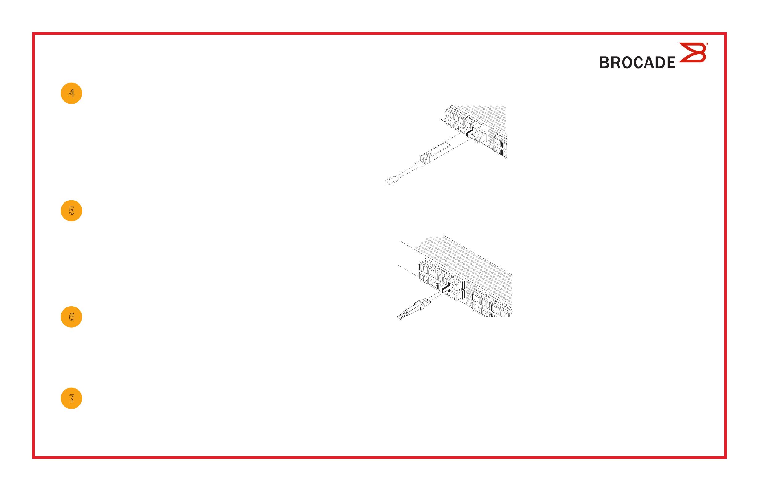
a. The 16 Gbps SFP+ transceivers have a long pull tab and no latching
wire bail. Remove any protector plugs from the SFP+ transceivers you
are going to use, and position and insert each SFP+ transceiver as
required (right side up in the top row of ports and upside down in the
bottom row of ports). Use the pull tab on the 16 Gbps SFP+ tranceivers
to help push the transceiver into the port.
If you are using 16 Gbps SFP+ transceivers, you may want to connect
the cable to the SFP+ first, and then insert them into the port as a unit.
If you are using 8 or 10 Gbps SFP+ transceivers, close the latching wire bail.
b. Repeat for the other ports.
a. Remove plastic protector caps from the Fibre Channel cable ends (if any),
and position the cable connector so that it is oriented correctly.
b. Insert the cable connector into the SFP+ transceiver until it is firmly
seated and the latching mechanism clicks.
c. The Configure Ports and Connect Devices screen shows missing,
valid, and invalid connections as you cable the switch. Note that it
can take up to 15 seconds for the connection to display as a valid
connection. Verify that the connections are all green and click Next.
!
© 2012 Brocade Communications Systems, Inc. All Rights Reserved.
53-1002706-01
*53-1002706-01*
!
Brocade, Brocade Assurance, the B-wing symbol, BigIron, DCX, Fabric OS, FastIron, MLX, NetIron, SAN Health, ServerIron, TurboIron, VCS, and VDX are
registered trademarks, and AnyIO, Brocade One, CloudPlex, Effortless Networking, ICX, NET Health, OpenScript, and The Effortless Network are trademarks
of Brocade Communications Systems, Inc., in the United States and/or in other countries. Other brands, products, or service names mentioned may be
trademarks of their respective owners.
設定交換機 IP 位址
4
1. Set Switch IP Address (設定交換機 IP 位址 ) 畫面中輸入必要的資訊。
2. 畫面中會提示您安裝 Active X 或某個版本的 Java 執行時期環境,請遵循提示進行安裝。如有需要,請重新啟動
安裝電腦。
3. 按一下 Next (下一步)
隨即顯示Confirm IP Address (確認 IP 位址) 畫面。
4. 按一下 Next (下一步) 以確認位址。
隨即顯示 Continue Configuration (繼續設定) 畫面。
5. 按一下 Continue with EZManager (繼續使用 EZManager)
1. SFP+ 收發器安裝於交換機上的光纖通道連接埠以符合螢幕上所顯示的連接埠。
2. 實體連接您的主機與儲存裝置。實體連線必須符合 Configure Ports and Connect Devices (設定連接埠及連接裝置)
畫面所示的連接方式。
3. Finish (完成) 畫面將顯示此訊息:Congratulations - you’ve successfully completed the setup! (恭喜 - 您已成功完成設定!)
如果您使用序列連線進行設定,則可移除序列纜線。
請參閱 EZSwitchSetup
瞭解更多有關自訂區域與其他交換機組態和管理選項的資訊。
繼續使用 EZManager
5
1. EZManager 上的 Welcome to Switch Configuration (歡迎至交換機設定) 的畫面上按一下 Next (下一步)
隨即顯示 Set Parameters (設定參數) 畫面。
2. Set Parameters (設定參數) 中建立新的管理員帳戶密碼。
3. 輸入新的交換機名稱 (選擇性步驟)
4. 調整您的時區的日期與時間 (選擇性步驟)
5. 按一下 Next (下一步)
設定區域並執行裝置選取
6
1. Select Zoning (選取區域) 畫面中選取 Typical Zoning (典型區域) 並按一下 Next (下一步)
預設區域設定為典型區域。
2. 在您要連線之交換機的 Device Selection (裝置選取) 畫面上輸入裝置類型。
EZSwitchSetup 會使用這些值自動組態交換機的連接埠。
連接裝置
7
Connect Devices (連接裝置) 畫面會依據您在設定區域並執行裝置選擇時所輸入的資訊,以圖形化的方式顯示交換機
與裝置的連線。此畫面將會顯示所有實體連線都是中斷的,直到您連接所指定的裝置為止。
a. 16 Gbps SFP+ 收發器上有一個長拉柄,沒有閂鎖纜線橫桿。移除您要
使用的 SFP+ 收發器上的所有保護蓋,並依照需要調整 SFP+ 收發器的
位置並將其插入 (連接上排的連接埠時必須右側朝上,連接下排的連接
埠時必須顛倒過來)。利用 16 Gbps SFP+ 收發器上的拉柄以便將收發器
插入連接埠。
如果您要使用 16 Gbps SFP+ 收發器,可能會想要先將纜線連接至 SFP+
再將它插入連接埠形成一個單元。
如果您要使用 8 10 Gbps SFP+收發器,請關閉閂鎖纜線橫桿。
b. 在其他連接埠上重複執行此動作。
a. 將光纖通道纜線端的塑膠保護蓋 (如果有的話) 取下,然後調整纜線接
頭的位置以使其方向正確。
b. 將纜線接頭插入 SFP+ 收發機直到確實固定,而且閂鎖機構發出嚓聲。
c. 當您連接或拔除交換機的纜線時,Configure Ports and Connect Devices
(設定連接埠及連接裝置) 畫面會顯示中斷、有效及無效的連線。請注意,
插入纜線之後最長約需 15 秒才會將該連線顯示為有效的連線。請檢查
連線是否均顯示為綠色,然後按一下 Next (下一步 )
!
© 2012 Brocade Communications Systems, Inc. 版權所有,翻印必究。
53-1002706-01
*53-1002706-01*
!
BrocadeBrocade AssuranceB-wing 標誌、BigIronDCXFabric OSFastIronMLXNetIronSAN HealthServerIronTurboIronVCS VDX
Brocade Communications Systems, Inc. 在美國及
/或其他國家或地區之註冊商標;AnyIOBrocade OneCloudPlexEffortless NetworkingICX
NET HealthOpenScript 以及 The Effortless Network Brocade Communications Systems, Inc. 在美國及/或其他國家或地區之商標。本文中的其他品牌、
產品或服務名稱屬於其擁有者之商標或服務商標。
管理員指南
1 / 1

Brocade Communications Systems Brocade 6520 Quick start guide

Category
Network switches
Type
Quick start guide

Ask a question and I''ll find the answer in the document

Finding information in a document is now easier with AI

Ask the document