Maytag IV45001 Installation guide
- Category
- Washing machines
- Type
- Installation guide

WASHERINSTALLATIONINSTRUCTIONS
INSTRUCTIONS POUR L'INSTALLATIONDE LALAVEUSE
Table of Contents/Table des matibres
WASHER SAFETY .................................................................................. 1
iNSTALLATiON REQUIREMENTS ......................................................... 2
Tools and Parts .................................................................................... 2
Location Requirements ........................................................................ 3
Drain System ....................................................................................... 3
Electrical Requirements ....................................................................... 4
iNSTALLATiON iNSTRUCTiONS ........................................................... 4
Before You Start .................................................................................. 4
Remove Shipping Materials ................................................................. 4
Connect Drain Hose ............................................................................ 6
Connect the Inlet Hoses ...................................................................... 6
Secure the Drain Hose ......................................................................... 7
Level the Washer ................................................................................. 7
Complete Installation ........................................................................... 8
SECURITE DE LA LAVEUSE .................................................................. 9
EXIGENCES D'INSTALLATION .............................................................. 9
Outillages et pieces ............................................................................. 9
Exigences d'emplacement ................................................................ 10
Syst_me de vidange .......................................................................... 10
Sp6cifications 61ectriques ................................................................. 11
iNSTRUCTiONS D'INSTALLATION ..................................................... 11
Avant de commencer ........................................................................ 11
Retrait du mat6riei d'expedition ........................................................ 11
Raccordement du tuyau de vidange ................................................. 13
Raccordement des tuyau× d'arriv6e d'eau ........................................ 13
Immobilisation du tuyau de vidange .................................................. 14
R6giage de I'aplomb de ia laveuse .................................................... 15
Achever I'installation .......................................................................... 16
WASHERSAFETY
Your safety and the safety of others are very important.
We have provided many important safety messages in this manual and on your appliance. Always read and obey all safety
messages.
This is the safety alert symbol.
This symbol alerts you to potential hazards that can kill or hurt you and others.
All safety messages will follow the safety alert symbol and either the word "DANGER" or "WARNING."
These words mean:
You can be killed or seriously injured if you don't immediately
follow instructions.
You can be killed or seriously injured if you don't follow
instructions.
All safety messages will tell you what the potential hazard is, tell you how to reduce the chance of injury, and tell you what can
happen if the instructions are not followed.
W10200331B

INSTALLATIONREQUIREMENTS
Gather the required tools and parts before starting installation.
The parts supplied are in the washer basket.
Parts needed (not provided with washer}:
m Inlet hoses m Flat washers
To order:
m Call the dealer from whom you purchased your washer.
m Reference the toll-free number on the front page of the
Washer User Instructions.
m Visit the website on the front page of the Washer User
Instructions.
NOTE: Replace inlet hoses after 5 years of use to reduce the
risk of hose failure. Record hose installation or replacement dates
for future reference.
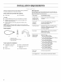
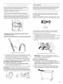
Parts supplied:
A B
A. Beaded tie strap
B. Front leveling feet with nuts (2)
C. Drain hose form
Tools needed for installation:
m Adjustable or open end
wrench %6" (14 mm)
m Level
m Wood block
m Ruler or measuring tape
m Pliers that open to 1,%6"
(3.95 cm)
m Flashlight (optional)
Alternate Parts
Your installation may require additional parts. For information on
ordering, please refer to the toll-free phone numbers on the front
page of the Washer User Instructions.
If You Have:
You Will Need to Buy:
Laundry tub or Sump pump system (if not already
standpipe taller available)
than 96" (2.4 m)
1" (2.5 cm)
diameter
standpipe
11A"(3.2 cm) diameter to 1" (2.5 cm)
diameter standpipe adapter,
Part Number 280130
Overhead sewer
Standard 20 gal. (76 L) 39" (99 cm) tall
drain tub or utility sink, sump pump, and
connectors (available from local
plumbing suppliers)
Floor drain
Water faucets
beyond reach
of fill hoses
Siphon break kit, Part Number 280129;
additional drain hose,
Part Number 3357090
Water fill hoses:
10 ft (3.0 m) Black EPDM,
Part Number 8212656RP
6 ft (1.8 m) Braided Nylon with 90° Elbow,
Part Number 8212638RP
5 ft (1.5 m) Braided Nylon,
Part Number 8212487RP
6 ft (1.8 m) Black EPDM with 90 ° Elbow,
Part Number 8212637RP
5 ft (1.5 m) Red & Blue EPDM,
Part Number 8212545RP
5 ft (1.5 m) Black EPDM,
Part Number 8212641RP
4 ft (1.2 m) Black EPDM,
Part Number 8212546RP
Drain hose Kit Part Number 280131
too short
Lint clogged drain Drain protector, Part Number 367031
2

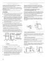
Selecting the proper location for your washer improves
performance and minimizes noise and possible washer "walk".
Your washer can be installed in a basement, laundry room, closet,
or recessed area. See "Drain System."
IMPORTANT: Do not install or store the washer where it will be
exposed to the weather.
Proper installation is your responsibility.
You will need:
m A water heater set to deliver 120°F (49°C) water to the washer.
m A grounded electrical outlet located within 4 ft (1.2 m) of
where the power cord is attached to the back of the washer.
See "Electrical Requirements."
m Hot and cold water faucets located within 3 ft (90 cm) of the
hot and cold water fill valves, and water pressure of 5-100 psi
(34.5-690 kPa). Washers with triple dispensers require
20-100 psi (138-690 kPa) for best performance.
m A level floor with a maximum slope of 1" (2.5 cm) under
entire washer. Installing the washer on carpeting is not
recommended.
m A sturdy floor to support the washer weight (washer, water,
and load) of 315 Ibs (143 kgs).
Do not store or operate your washer in temperatures at or below
32°F (0°C). Some water can remain in the washer and can cause
damage in tow temperatures. See "Washer Care" in the Washer
User Instructions for winterizing information.
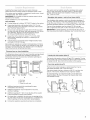
Recessed area or closet installation
The dimensions shown are for the recommended spacing allowed
(A and B), except the closet door ventilation openings. The
dimensions shown for the closet door ventilation openings (C)
are the minimum required.
m
0"_1 6- _" _1 6- 0" _"_25,_'_q
_! _"max. IF-----3 _._0al
(310_
241n._ _ _ I
__g.6ca)
|
(_o2_)
A B C
A. Front view
B. Side view
C. Closet door with vents
m Additional spacing should be considered for ease
of installation and servicing.
m Additional clearances may be required for wall, door,
and floor moldings.
m Additional spacing of 1" (2.5 cm) on all sides of the washer
is recommended to reduce noise transfer.
m
If a closet door is installed, the minimum air openings in the
top and bottom of the door are required (C). Louvered doors
with air openings in the top and bottom are acceptable.
Companion appliance spacing should also be considered.
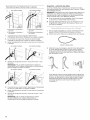
The washer can be installed using the standpipe drain system
(floor or wall), the laundry tub drain system, or the floor drain
system. Select the drain hose installation method you need.
See "Tools and Parts."
Standpipe drain system--wall or floor (views A & B)
i ,i
The standpipe drain requires a minimum diameter standpipe of
2" (5 cm). The minimum carry-away capacity can be no less than
17 gal. (64 L) per minute. A I_A" (3.2 cm) diameter to 1" (2.5 cm)
diameter standpipe adapter kit is available. See "Tools and Parts."
The top of the standpipe must be at least 39" (99 cm) high
and no higher than 96" (244 cm) from the bottom of the washer.
IMPORTANT: To avoid siphoning, no more than 8" (20.3 cm) of
drain hose should be inside the standpipe. See "Connect drain hose."
Laundry tub drain system (view C)
The laundry tub needs a minimum 20 gal. (76 L) capacity. The top
of the laundry tub must be at least 39" (99 cm) above the floor and
no higher than 96" (244 cm) from the bottom of the washer.
Floor drain system (view D)
The floor drain system requires a siphon break that may be
purchased separately. See "Tools and Parts."
The siphon break must be a minimum of 28" (71 cm) from the
bottom of the washer. Additional hoses might be needed.
Toavoid siphoning, no more than 8" (20.3 cm) of drain hose
should be below the top of the wash tub. Secure drain hose
with beaded tie strap.
(7t crn)
C

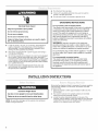
Electrical Shock Hazard
Plug into a grounded 3 prong outlet.
Do not remove ground prong.
Do not use an adapter.
Do not use an extension cord.
Failure to follow these instructions can result in death,
fire, or electrical shock.
m A 120 volt, 60 Hz., AC only, 15- or 20-amp, fused electrical
supply is required. A time-delay fuse or circuit breaker is
recommended. It is recommended that a separate circuit
serving only this appliance be provided.
m This washer is equipped with a power supply cord having a
3 prong grounding plug.
m To minimize possible shock hazard, the cord must be plugged
into a mating, 3 prong, grounding-type outlet, grounded in
accordance with local codes and ordinances. If a mating outlet
is not available, it is the personal responsibility and obligation
of the customer to have the properly grounded outlet installed
by a qualified electrician.
[] If codes permit and a separate ground wire is used, it is
recommended that a qualified electrician determine that
the ground path is adequate.
[] Do not ground to a gas pipe.
[] Check with a qualified electrician if you are not sure the
washer is properly grounded.
[] Do not have a fuse in the neutral or ground circuit.
GROUNDING INSTRUCTIONS
For a grounded, cord=connected washer:
This washer must be grounded. In the event of a malfunction
or breakdown, grounding will reduce the risk of electrical
shock by providing a path of least resistance for electric
current. This washer is equipped with a cord having an
equipment-grounding conductor and a grounding plug. The
plug must be plugged intoan appropriate outlet that is
properly installed and grounded in accordance with all local
codes and ordinances.
WARNING: Improper connection of the equipment-
grounding conductor can result in a risk of electric shock.
Check with a qualified electrician or serviceman if you are in
doubt as to whether the appliance is properly grounded.
Do not modify the plug provided with the appliance -if it will
not fit the outlet, have a proper outlet installed by a qualified
electrician.
For a permanently connected washer:
This washer must be connected to a grounded metal,
permanent wiring system, or an equipment grounding
conductor must be run with the circuit conductors and
connected to the equipment-grounding terminal or lead on
the appliance.
INSTALLATIONINSTRUCTIONS
Excessive Weight Hazard
Use two or more people to move and install washer.
Failure to do so can result in back or other injury.
NOTE: To avoid floor damage, set the washer onto cardboard
before moving across floor.
Removing the shipping material is necessary for proper operation.
If the shipping material is not removed, the washer will make
excessive noise.
1. Move the washer to within approximately 3 ft (90 cm) of its
final location.
2=
3.
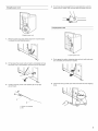
The washer must be in the upright position and not tilted
before removing the shipping material.
Locate the yellow shipping materials on the rear of the
machine, near the bottom. Follow the steps for your particular
model, either the one with the straight power cord and cord
restraint or the looped power cord version.
4

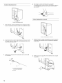
1.
2.
3.
Straight power cord
Remove power plug and yellow strap from machine base
to release the rear beveling system.
I
Firmly grasp the power cord and pull to completely remove
the power cord, cord restraint, and pin from the rear panel.
Confirm that the power cord restraint (A) and pin (B)
are removed.
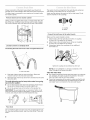
Looped power cord
1.
2.
Looped power cord
Firmly grasp the yellow shipping strap and pull until both ends
are completely removed from washer.
U
Check that two (2) cotter pins were removed with the shipping
strap.
A. Power cord restraint
B. Pin

Proper connection of the drain hose protects your floors from
damage due to water leakage. Read and follow these instructions.
The drain hose is connected to your washer and is stored inside
the washer cabinet.
Laundry tub drain or standpipe drain
Connecting the drain hose form to the corrugated drain hose
The washer must be connected to the water faucets using new
inlet hoses (not provided). Do not use old hoses.
Insert new flat washers into each end of the inlet hoses. Firmly
seat the washers in the couplings.
A B
A.Coupling
B. Washer
Connect the inlet hoses to the water faucets
Make sure the washer basket is empty.
1. Attach hose to the hot water faucet. Screw on coupling
by hand until it is seated on the washer.
2. Attach hose to the cold water faucet. Screw on coupling
by hand until it is seated on the washer.
3. Using pliers, tighten the couplings with an additional
two-thirds turn.
A
A. Drain hose reliefs
1. Feed end of drain hose into one end of form. Place end
of drain hose form into the drain hose relief.
2. Bend the hose over the top of the form and feed into the other
end of the form.
To avoid siphoning and to keep drain water from going
back into the washer:
m Do not force excess drain hose into standpipe. Hose should
be secure but loose enough to provide a gap for air.
=1 Do not lay excess hose on the bottom of the laundry tub.
IMPORTANT: To avoid siphoning, no more than 8" (20.3 cm) of
drain hose should be inside the standpipe. The drain hose form
must be used. Secure drain hose with beaded tie strap.
2°o3211
Floor drain
Do not install the drain hose form onto the corrugated drain hose.
You may need additional parts. See Floor drain under "Tools and
Parts."
Tighten the couplings with an additional two-thirds turn.
NOTE: Do not overtighten or use tape or sealants on the
valve. Damage to the valves can result.
Clear the water lines
[] Run water through both faucets and inlet hoses, into a laundry
tub, drainpipe, or bucket, to get rid of particles in the water
lines that might clog the inlet valve screens.
[] Check the temperature of the water to make sure that the hot
water hose is connected to the hot water faucet and that the
cold water hose is connected to the cold water faucet.
6

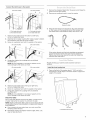
Connect the inlet hoses to the washer
(Onsomemodels) (Onsomemodels)
A B
A. Cold waterinletvalve
B.Hotwaterinletvalve
A. Cold water inlet valve
B. Hot water inlet valve
1. Attach the hot water hose to the bottom (or left-hand,
on some models) inlet valve.
2. Attaching the hot water coupling first makes it easier to tighten
the connection with pliers (on some models).
3. Screw on coupling by hand until it is seated on the washer.
(Onsomemodels) (On some models)
Using pliers, tighten the couplings with an additional
two-thirds turn.
NOTE: Do not overtighten or use tape or sealants on the
valve. Damage to the valves can result.
(On some models) (On some models)
1. Remove the shipping material from the power cord. Drape the
power cord over the console.
2. Remove any cardboard used to move the washer.
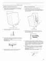
3=
Beadedtiestrap
Wrap the drain hose to the laundry tub leg, drain standpipe,
or inlet hoses with the beaded tie strap. Push fastener into
the nearest hole in the beaded tie strap. See view A or B.
A c
If the washer faucets and the drain standpipe are recessed,
put the formed end of the drain hose into the standpipe.
Tightly wrap the tie strap around the water inlet hoses and
the drain hose. See view C.
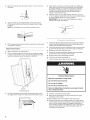
Properly leveling your washer avoids excessive noise and
vibration.
install the front leveling feet
1. Prop up the front of the washer about 4" (10.2 cm) with a
wood block or similar object. The block needs to support the
weight of the washer.
5. Attach the cold water hose to the top (or right-hand,
on some models) inlet valve.
6. Screw on coupling by hand until it is seated on the washer.
7. Using pliers, tighten the couplings with an additional
two-thirds turn.
NOTE: Do not overtighten or use tape or sealants on the
valve. Damage to the valves can result.
Check for leaks
Turn on the water faucets and check for leaks. A small amount
of water might enter the washer. You will drain this later.
NOTE: Replace inlet hoses after 5 years of use to reduce the risk
of hose failure. Record hose installation or replacement dates for
future reference.
m If you connect only one water hose, you must cap off the
remaining water inlet port.
m Periodically inspect and replace hoses if bulges, kinks, cuts,
wear, or leaks are found.
4 I
(10.2 cm)
A. Threaded holes for feet

2=
3=
Screw the Iocknut onto each foot to within 1" (2.5 cm) of the
foot base.
(2.5 crn)
Screw the feet into the threaded holes at the front corner
of the washer until the nuts touch the washer. Twist the feet
to install.
NOTE: Do not tighten the nuts until the washer is level.
4. If the washer is not level, move the washer out slightly, tip
back, prop up the front of the washer with the wood block
and adjust the feet up or down as necessary by twisting
the feet. Turn the feet clockwise to raise the washer or
counterclockwise to lower the washer. Repeat steps 1
through 4 until washer is level.
5. After the washer is in the final location and level, use a 9A6"
or 14 mm open-end wrench to turn the nuts counterclockwise
on the feet tightly against the washer cabinet.
IMPORTANT: Ifthe nuts are not tight against the washer
cabinet, the washer may vibrate.
4. Tilt the washer back and remove the wood block. Gently lower
the washer to the floor.
Steps in final location
1. Slide the washer to its final location.
2. Tilt the washer forward until the rear of the washer is at least
4" (10.2 cm) off the floor. You may hear the self-adjusting rear
feet click into place. Lower the washer to the floor.
3=
A. Self-adjusting feet
Check the levelness of the washer by placing a level on the
top edges of the washer, first side to side, then front to back.
1. Check the electrical requirements. Be sure that you have the
correct electrical supply and the recommended grounding
method. See "Electrical Requirements."
2. Check that all parts are now installed. Ifthere is an extra part,
go back through the steps to see which step was skipped.
3. Check that you have all of your tools.
4. Check that the yellow shipping materials were completely
removed from the lower back of the washer.
5=
6.
7.
Dispose of/recycle all packaging materials.
Check that the water faucets are on.
Check for leaks around faucets and inlet hoses.
Electrical Shock Hazard
Plug into a grounded 3 prong outlet.
Do not remove ground prong.
Do not use an adapter.
Do not use an extension cord.
Failure to follow these instructions can result in death,
fire, or electrical shock.
8. Plug into a grounded 3 prong outlet.
9. Remove the protective film on the console and any tape
remaining on the washer.
10. Read "Washer Use" in the Washer User Instructions.
11. To test and to clean your washer, measure 1_of the normal
recommended amount of powdered or liquid detergent and
pour it into the washer basket or detergent dispenser (on
some models). Close the lid. Select any cycle, and then pull
the cycle control knob out to start the washer. Allow it to
complete one whole cycle.
8
Page is loading ...
Page is loading ...
Page is loading ...
Page is loading ...
Page is loading ...
Page is loading ...
Page is loading ...
Page is loading ...
-
 1
1
-
 2
2
-
 3
3
-
 4
4
-
 5
5
-
 6
6
-
 7
7
-
 8
8
-
 9
9
-
 10
10
-
 11
11
-
 12
12
-
 13
13
-
 14
14
-
 15
15
-
 16
16


Maytag IV45001 Installation guide
- Category
- Washing machines
- Type
- Installation guide
Ask a question and I''ll find the answer in the document
Finding information in a document is now easier with AI
in other languages
- français: Maytag IV45001 Guide d'installation
Related papers
-
Maytag BRAVOSTM User manual
-
-
Maytag MTW5807TQ0 User manual
-
-
-
-
Whirlpool RTW4440VQ2 Installation guide
-
-
Whirlpool WGT3300SQ2 Installation guide
-
Whirlpool MHW6000XW2 Installation guide
Other documents
-
Estate ETW4300T User manual
-
-
Amana NTW5245T User manual
-
Roper RTW4100S User manual
-
-
-
Magic Chef 2DHTW4305TQ0 Installation guide
-
 Kenmore Elite 11028081700 User manual
-
-
