Page is loading ...

Pin Nailer
FRANÇAISE: Page 17
ESPAÑOL: Página 33
MAKES IT EASY TO DO IT LIKE A PRO chpower.com
Operating Instructions and Parts Manual
CHN71500
IN730100AV 2/10
© 2010 Campbell Hausfeld/Scott Fetzer

Description . . . . . . . . . . . . . . . . . . . . . . . . . 3
Specifications . . . . . . . . . . . . . . . . . . . . . . . 3
Safety Guidelines. . . . . . . . . . . . . . . . . . . . 4
Safety Symbols . . . . . . . . . . . . . . . . . . . . . . 4
Important Safety Information . . . . . . . . 4
Instructions Pertaining to a Risk
of Fire, Electric Shock, or Injury
to Persons. . . . . . . . . . . . . . . . . . . . . . . . . 4
California Proposition 65 . . . . . . . . . . . 4
General . . . . . . . . . . . . . . . . . . . . . . . . . . . 4
Work Area. . . . . . . . . . . . . . . . . . . . . . . . . 4
Personal Safety . . . . . . . . . . . . . . . . . . . . 5
Electrical Safety. . . . . . . . . . . . . . . . . . . . 5
Tool Use and Care . . . . . . . . . . . . . . . . . 5
Service. . . . . . . . . . . . . . . . . . . . . . . . . . . . 6
Air Source. . . . . . . . . . . . . . . . . . . . . . . . . 6
Unpacking. . . . . . . . . . . . . . . . . . . . . . . . . . 6
Contents. . . . . . . . . . . . . . . . . . . . . . . . . . 6
Additional Items Not Included . . . . . . 6
Assembly . . . . . . . . . . . . . . . . . . . . . . . . . . . 6
Glossary . . . . . . . . . . . . . . . . . . . . . . . . . . . . 7
Getting To Know Your
Pin Nailer Like A Pro. . . . . . . . . . . . . . . . . 8
Features . . . . . . . . . . . . . . . . . . . . . . . . . . . . 8
Adjustable Exhaust Deflector . . . . . . . 8
No-mar Tip . . . . . . . . . . . . . . . . . . . . . . . 8
Rubber Comfort Grip . . . . . . . . . . . . . . 8
Self-adjusting Pin Length
Mechanism . . . . . . . . . . . . . . . . . . . . . . . 8
Set-Up . . . . . . . . . . . . . . . . . . . . . . . . . . . . . 9
Lubrication . . . . . . . . . . . . . . . . . . . . . . . 9
Minimum Components Required
for Hook-up. . . . . . . . . . . . . . . . . . . . . . . 9
Hook-up Instructions For Nailer
to Air Supply . . . . . . . . . . . . . . . . . . . . . . 9
Air Hose Requirements. . . . . . . . . . . . . 9
Loading / Unloading The Nailer . . . . 10
Loading the Nailer . . . . . . . . . . . . . . 10
Unloading the Nailer . . . . . . . . . . . . 10
Installing No-Mar Tip . . . . . . . . . . . . . 10
Removing No-Mar Tip . . . . . . . . . . . . 10
Pre-Operation. . . . . . . . . . . . . . . . . . . . . . 11
Operational Modes . . . . . . . . . . . . . . . 11
Sequential Mode. . . . . . . . . . . . . . . . 11
Work Contact Element (WCE). . . . . . 11
Adjusting the Direction of the
Exhaust . . . . . . . . . . . . . . . . . . . . . . . . . . 11
Operation . . . . . . . . . . . . . . . . . . . . . . . . . 12
Firing the Nailer . . . . . . . . . . . . . . . . . . 12
Storage . . . . . . . . . . . . . . . . . . . . . . . . . . . . 12
Maintenance. . . . . . . . . . . . . . . . . . . . . . . 12
Clearing a Jam from the Nailer . . . . . 12
Nailer Repair . . . . . . . . . . . . . . . . . . . . . 12
Replacement Parts. . . . . . . . . . . . . . . . 12
Assembly Procedure for Seals . . . . . . 12
Technical Service . . . . . . . . . . . . . . . . . 12
Fastener Interchange Information. . 13
Troubleshooting Guide . . . . . . . . . . . . . 13
Replacement Parts List
for Brad Nailer . . . . . . . . . . . . . . . . . 14 - 15
Warranty . . . . . . . . . . . . . . . . . . . . . . . . . . 16
Table of Contents
For parts, product and service information
Visit: www.chpower.com
Call : Customer Service at 1-800-543-6400
Address any correspondence to: Campbell Hausfeld
Attn: Customer Service
100 Production Drive
Harrison, OH 45030 U.S.A.

Operating Instructions and Parts Manual
Pin Nailer
www.chpower.com
3
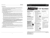
Description
This pin nailer is designed for tacking decorative trim, glazing strips, and picture frame
assembly. Features include: convenient side loading magazine which holds up to
135 pins, no-mar tip, oil free, rubber comfort grip, swivel plug, work contact element,
self-adjusting pin length mechanism, and adjustable exhaust.
Figure 1 - CHN71500 Pin Nailer
Specifications
Model CHN71500
Requires: 0.15 Avg SCFM using 10
fasteners per minute at 90 psi
Air Inlet: 1/4 inch NPT
Fastener Size Range:
23g micropins - 3/8 inch to 7/8 inch
Magazine Capacity: 135 fasteners per
load
Weight: 2 lbs.
Length: 9-1/4 inches
Height: 7-1/4 inches
Maximum Pressure: 100 psi
Pressure Range: 60 psi to 100 psi
Locate model number and date code on
magazine and / or tool body. Record below:
Model #: _____________________________
Date Code: ___________________________
Retain these numbers for future reference.

Safety Guidelines
This manual contains
information that is very
important to know and
understand. This information
is provided for SAFETY and
to PREVENT EQUIPMENT
PROBLEMS. To help recognize
this information, observe the
following symbols.
Danger
indicates an
imminently hazardous situation
which, if not avoided, WILL result
in death or serious injury.
Warning
indicates a
potentially hazardous situation
which, if not avoided, COULD
result in death or serious injury.
Caution
indicates a
potentially hazardous situation
which, if not avoided, MAY result in
minor or moderate injury.
Notice
indicates
important information, that if not
followed, may cause damage to
equipment.
NOTE: Information that
requires special attention.
Safety Symbols
The following Safety Symbols
appear throughout this manual
to alert you to important safety
hazards and precautions.
Important Safety Information
INSTRUCTIONS PERTAINING TO A RISK OF FIRE, ELECTRIC SHOCK, OR
INJURY TO PERSONS
This manual contains important safety, operational and maintenance information. If
you have any questions, please call 1-800-543-6400 for customer assistance.
When using tools, basic precautions should always be followed,
including the following:
CALIFORNIA PROPOSITION 65
This product or its power cord may contain chemicals known to the State
of California to cause cancer and birth defects or other reproductive
harm. Wash hands after handling.
You can create dust when you cut, sand, drill or grind
materials such as wood, paint, metal, concrete, cement, or
other masonry. This dust often contains chemicals known to cause cancer, birth
defects, or other reproductive harm. Wear protective gear.
GENERAL
a. To reduce the risks of electric shock, fire, and injury to persons, read
all the instructions before using the tool. Failure to follow warnings,
dangers, and cautions could result in DEATH or SERIOUS INJURY.
b. Be thoroughly familiar with the controls and the proper use of the
equipment. Follow all instructions. Contact your Campbell Hausfeld representative
if you have any questions.
c. Only persons well acquainted with these rules of safe operation should be allowed
to use the unit.
Do not operate or allow anyone else to operate the nailer if any warnings
or warning labels are not legible. Warnings or warning labels are located
on the nailer magazine and body.
Always assume the nailer contains nails. Respect the tool as a working
implement; no horseplay. Always keep others at a safe distance from
the work area in case of accidental discharge of nails. Do not point the tool toward yourself or
anyone whether it contains fasteners or not. Accidental triggering of the nailer could result in
death or serious personal injury.
Do not make any modifications to the tool without first obtaining
written approval from Campbell Hausfeld. Do not use the nailer if any
shields or guards are removed or altered. Do not use the nailer as a hammer. Personal injury or
tool damage may occur.
Clean and check all air supply hoses and fittings before connecting the
nailer to an air supply. Replace any damaged or worn hoses or fittings.
Tool performance or durability may be reduced.
WORK AREA
a. Keep the work area clean and well lighted. Cluttered benches and dark areas
increase the risks of electric shock, fire, and injury to persons.
b. Do not operate the tool in explosive atmospheres, such as in the
presence of flammable liquids, gases, or dust. The tool is able to create
sparks resulting in the ignition of the dust or fumes.
c. Keep bystanders, children, and visitors away while operating the tool.
Distractions are able to result in the loss of control of the tool.
Operating Instructions and Parts Manual
www.chpower.com
Risk of
Personal
Injury
Risk of Fire
Wear Eye
and Mask
Protection
Read Manual
First
Risk of
Explosion
Risk of Falling Wear Eye
Protection
Wear Hearing
Protection
Risk of Shock
CHN71500
4

ELECTRICAL SAFETY
The front end of the tool may be
made “live” if the tool comes
into contact with live wiring in the wall. TO PREVENT
ACCIDENTAL ELECTRICAL SHOCK, HOLD TOOL ONLY BY
THE SOFT GRIP HANDLE.
TOOL USE AND CARE
a. Do not force the tool. Use the correct tool for the application.
The correct tool will do the job better and safer at the rate for
which the tool is designed.
Disconnect the tool from the air source before
making adjustments, doing tool maintenance,
clearing jams, touching the safety yoke, leaving work area, loading,
or unloading the tool. Such precautionary measures reduce the risk of
injury to persons.
b. Store the tool when it is idle out of reach of children and
other untrained persons. A tool is dangerous in the hands of
untrained users.
c. Maintain the tool with care. A properly maintained tool
reduces the risk of problems and is easier to control.
d. Use only those fasteners listed in the “Fastener Interchange
Information” section on page 12 of this manual. Fasteners
not identified for use with this tool by the tool manufacturer
are able to result in a risk of injury to persons or tool damage
when used in this tool.
e. Always work in a well-ventilated area. Wear OSHA-
approved dust mask.
Always disconnect the tool from the power
source when unattended, performing any
maintenance or repair, clearing a jam, loading, unloading , or moving
the tool to a new location.
Always fit tool with a fitting or hose coupling
on or near the tool in such a manner that all
compressed air in the tool is discharged at the time the fitting or hose
coupling is disconnected. Do not use a check valve or any other fitting
which allows air to remain in the nailer. Death or serious personal
injury could occur.
Never carry the nailer by the air hose or pull
the hose to move the nailer or a compressor.
Keep hoses away from heat, oil and sharp edges. Replace any hose
that is damaged, weak or worn. Personal injury or tool damage could
occur.
Do not drive a nail on top of other nails. The
nail could glance and cause death or a serious
puncture wound.
f. Do not remove any labels from the tool.
g. Do not modify or alter the nailer or any nailer parts. Do
not use the nailer if any shields or guards are removed or
altered. Do not use the nailer as a hammer. Personal injury or
tool damage may occur.
Do not use any type of flammable gases or
oxygen as a power source for the nailer.
Use filtered, lubricated, regulated compressed air only. Use of a
compressed gas instead of compressed air may cause the nailer to
explode which will cause death or serious personal injury.
PERSONAL SAFETY
a. Stay alert. Watch what you are doing and use common
sense when operating the tool. Do not use the tool
while tired or under the influence of drugs, alcohol, or
medication. A moment of inattention while operating the
tool increases the risk of injury to persons.
b. Dress properly. Do not wear loose clothing or jewelry.
Contain long hair. Keep hair, clothing, and gloves away
from moving parts. Loose clothes, jewelry, or long hair
increases the risk of injury to persons as a result of being
caught in moving parts.
c. Do not overreach. Keep proper footing and
balance at all times. Proper footing and balance
enables better control of the tool in unexpected
situations.
d. Use safety equipment. A dust mask, non-skid safety shoes
and a hard hat must be used for the applicable conditions.
Ensuring that the tool is used
only when the operator and all
other personnel in the work area are wearing ANSI Z87
eye protection equipment, and when required, other
appropriate protection equipment such as head, hearing
and foot protection equipment. Serious eye or permanent hearing
loss could result.
e. Always wear hearing protection when using the
tool. Prolonged exposure to high intensity noise
is able to cause hearing loss.
f. Do not attach the hose or tool to your body. Attach the
hose to the structure to reduce the risk of loss of balance if
the hose shifts.
g. Always assume that the tool contains fasteners.
Do not point the tool toward yourself or anyone
whether it contains fasteners or not.
Do not drop or throw the tool. Dropping
or throwing the tool can result in damage that
will make the tool unusable or unsafe. If the tool has been dropped
or thrown, examine the tool closely for bent, cracked or broken parts
and air leaks. STOP and repair before using or serious injury could
occur.
Avoid long extended periods of work with the
nailer. Stop using the nailer if you feel pain in
hands or arms.
Hold tool by insulated gripping surface when
performing an operation where the tool or
fastener may contact hidden wiring. Contacting a “live” wire will
make exposed metal parts of the tool “live” and shock the operator.
Never place hands or any other
body parts in the nail discharge
area of the nailer. The nailer might eject a fastener and
could result in death or serious personal injury.
CHN71500
www.chpower.com
Important Safety Information (Continued)
Operating Instructions and Parts Manual
5

Operating Instructions and Parts Manual
Important Safety Information (Continued)
Never use gasoline or other flammable liquids
to clean the nailer. Never use the nailer in
the presence of flammable liquids or gases. Vapors could ignite by a
spark and cause an explosion which will result in death or serious
personal injury.
h. Avoid using the nailer when the magazine is empty.
Accelerated wear on the nailer may occur.
Do not modify or disable the Work Contact
Element (WCE). Do not tie or tape the WCE
or trigger in a depressed position. Death or serious personal injury
could result.
Always check that the Work Contact Element
(WCE) is operating properly. A nail could
accidentally be driven if the WCE is not working properly. Personal
injury may occur.
Do not touch the trigger unless driving nails.
Never attach air line to nailer or carry nailer
while touching the trigger. The tool could eject a fastener which will
result in death or serious personal injury.
SERVICE
a. Tool service must be performed only by qualified repair
personnel.
b. When servicing a tool, use only identical replacement
parts. Use only authorized parts.
c. Use only the lubricants supplied with the tool or specified
by the manufacturer.
Disconnect air supply and release tension
from the pusher before attempting to clear
jams because fasteners can be ejected from the front of the nailer.
Personal injury may occur.
AIR SOURCE
a. Never connect to an air source that is capable of exceeding
200 psi. Over pressurizing the tool is able to result in
bursting, abnormal operation, breakage of the tool or
serious injury to persons. Use only clean, dry, regulated
compressed air at the rated pressure or within the rated
pressure range as marked on the tool. Always verify prior to
using the tool that the air source has been adjusted to the
rated air pressure or within the rated air-pressure range.
b. Never use oxygen, carbon dioxide, combustible gases or
any bottled gas as an air source for the tool. Such gases are
capable of explosion and serious injury to persons.
Air compressors providing air to the nailer
should follow the requirements established
by the American National Standards Institute Standard B19.3-1991;
Safety Standard for Compressors for Process Industries. Contact your
air compressor manufacturer for information.
SAVE THESE INSTRUCTIONS
DO NOT DISCARD
Unpacking
After unpacking the unit, inspect carefully for any damage that
may have occurred during transit. Check for loose, missing
or damaged parts. Make sure to tighten fittings, bolts, etc.,
before putting unit into service. Check to be sure all supplied
accessories are enclosed with the unit. In case of questions,
damaged or missing parts, please call 1-800-543-6400 for
customer assistance.
CONTENTS
u Pin Nailer
u 3/4 inch, 23 gauge headless micropins
u Operating Instructions
u Warranty Card
u Carry Bag
u Wrenches
ADDITIONAL ITEMS NOT INCLUDED
u Compressor (must be able to maintain a minimum of 60 psi
when the nailer is being used)
u Air hose
u Small tool for clearing jams
u Threadlock glue
u ANSI Z87 eye protection
u Hearing protection and other personal protective
equipment as required
Assembly
This tool comes fully assembled.
The DANGER, WARNING, CAUTION, and NOTICE
notifications and instructions in this manual cannot
cover all possible conditions and situations that may
occur. It must be understood by the operator that
common sense and caution are factors which cannot
be built into this product, but must be supplied by the
operator.
CHN71500
www.chpower.com
6

Operating Instructions and Parts Manual
www.chpower.com
CHN71500
7
Glossary
Become familiar with these terms before operating the unit.
ACTUATE (TOOL) — To cause movement to the tool’s component(s) intended to
drive the fastener.
ACTUATION SYSTEM — The use of a trigger, work contact element (WCE) and/
or other operating control, separately or in combination or sequence, to actuate
the tool.
AIR INLET — The opening in which the compressed air supply is connected,
usually by means of a threaded fitting.
FASTENERS — This pin nailer uses 23g Pin Nails ranging in size from 3/8 inch to
7/8 inch.
MAGAZINE — The part of the nailer that holds the Fasteners.
MAXIMUM AIR PRESSURE — The maximum allowable pressure of compressed
air, as specified by the manufacture, for operating the tool.
NO-MAR TIP — The no-mar tip is designed to eliminate marks caused by the
Work Contact Element (WCE) (see Figure 4). The no-mar tip may be removed
if not required (See REMOVING NO-MAR TIP) or when a slightly deeper
countersink is preferred. Simply slide the no-mar off the WCE.
psi (POUNDS PER SQUARE INCH) —Measurement of the pressure exerted by
the force of the air. The actual psi output is measured by a pressure gauge on the
compressor.
QUICK COUPLER — A quick coupler is designed to work in combination with a
quick plug to quickly and easily join a pneumatic tool to an air hose (see Figure 2).
QUICK PLUG — A quick plug is designed to work in combination with a quick
coupler to quickly and easily join a pneumatic tool to an air hose (see Figure 3).
REGULATOR — A device used to control air pressure to an air operated tool
THREAD LOCK GLUE — A locking glue that is applied to the screw threads
before installing. Prevents the screws from working loose during tool operation.
Figure 2 - Quick Coupler
Figure 3 - Quick Plug
Figure 4
No-mar
Tip

ADJUSTABLE EXHAUST
DEFLECTOR
This tool is equipped with an adjustable
exhaust deflector feature. This allows
for the tool exhaust to be redirected in
any position that is convenient for the
user. Turn the deflector to any direction
desired.
NO-MAR TIP
The tool is fitted with a no-mar tip. To
utilize the no-mar tip, simply slide it over
the tool’s WCE.
RUBBER COMFORT GRIP
The tool is fitted with a rubber comfort
grip. This helps to maintain a steady grip
and prevents fatigue.
SELF-ADJUSTING PIN LENGTH
MECHANISM
The tool is equipped with a convenient
self-adjusting pin length mechanism.
Simply load the desired pins in the
magazine and let the tool self-adjust.
Getting To Know Your Pin Nailer Like A Pro
Figure 5 - Components of the Pin Nailer
CHN71500
www.chpower.com
Operating Instructions and Parts Manual
8
No-mar
Tip
Trigger
Work Contact
Element (WCE)
Pull-out
Warning
Decal
Swivel Plug
Magazine
Latch
Nail Loading
Area
Adjustable
Exhaust
Deflector
Magazine
Rubber
Comfort
Grip

Operating Instructions and Parts Manual
www.chpower.com
CHN71500
9
Set-Up
LUBRICATION
This nailer requires NO lubrication for normal operation. However, lubrication will
NOT harm the tool.
The work surface can become damaged by excessive lubrication.
MINIMUM COMPONENTS REQUIRED FOR HOOK-UP
AIR COMPRESSOR: The air compressor must be able to maintain a minimum of 60 psi
when the nailer is being used. An inadequate air supply can cause a loss of power and
inconsistent driving (see Chart 1).
PRESSURE REGULATOR: A pressure regulator is required to control the operating
pressure of the nailer between 60 psi and 100 psi.
AIR SUPPLY HOSE: ALWAYS use air supply hoses with a minimum working pressure
rating equal to or greater than the pressure from the power source, or 150 psi,
whichever is greater. Use 1/4 inch air hose for runs up to 50 feet. Use 3/8 inch air hoses
for 50 ft. run or longer (see Figure 6 and Chart 2).
HOOK-UP INSTRUCTIONS FOR NAILER TO AIR SUPPLY
Figure 8 shows the recommended hookup for the nailer.
NOTE: For better performance, install a 3/8 inch quick plug (1/4 inch NPT threads) with
an inside diameter of 0.315 inch (8 mm) on the nailer and a 3/8 inch quick coupler on
the air hose.
1. With ON/OFF switch in OFF position, plug compressor into electrical outlet.
2. Close pressure regulator by turning all the way to the left. Turn compressor ON and
let it pump all the way up to automatic shut-off pressure.
3. Attach air hose to regulator outlet. Adjust pressure regulator by turning to the right
so that outlet pressure is between 60 psi to 100 psi.
4. Load fasteners into nailer (See Loading/Unloading the Nailer section on page 10).
5. Point the nailer in a safe direction while attaching to air hose.
6. Nailer is ready for use. You may need to adjust outlet pressure to achieve proper
fastener depth.
60 psi Minimum
100 psi Maximum
Chart 1
AIR HOSE REQUIREMENTS
DIAMETER LENGTH OF RUN
1/4 inch Less than 50 feet
3/8 inch Greater than or equal
to 50 feet
Chart 2
Figure 6 - Air Hose Requirements
Interior Diameter
Rated 150 psi or greater
Figure 7 - Recommended Hookup
Tank
Pressure
Gauge
Outlet
Pressure
Gauge
Regulator
Outlet
Regulator
Quick
Coupler
Quick
Plug
Swivel
Plug
Quick
Coupler
Air
Hose

CHN71500
www.chpower.com
Operating Instructions and Parts Manual
10
LOADING / UNLOADING THE TOOL
Always disconnect the tool from the air supply before loading / unloading fasteners.
Choose which type of fastener you want to use for you project. Additional fasteners can
be found at major home centers.
Loading the Tool
1. Push the latch button. Pull back on the magazine cover fully.
2. Insert a stick of pins into the magazine under the automatic nail length plate. Make
sure pointed ends of pins are resting on bottom ledge of magazine when loading.
Make sure pins are not dirty or damaged. Pins are marked for direction of loading.
3. Push the magazine cover forward until latch engages.
Unloading the Tool
1. Push the latch button. Pull back on the magazine cover fully.
2. Remove the pins from the magazine.
3. Push the magazine cover forward until latch engages.
4. Always unload all fasteners before removing tool from service. Unloading is the
reverse of loading, except always disconnect the air supply before unloading.
INSTALLING NO-MAR TIP
1. Disconnect air supply from nailer.
2. Carefully place no-mar tip over the end of work contact element.
3. Check that the WCE and trigger move up and down freely without sticking or
binding.
REMOVING NO-MAR TIP
1. Disconnect air supply from nailer.
2. Pry no-mar tip away from the work contact element.
Set-Up (Continued)
Figure 8 - Loading the Nailer
Figure 9 - No-mar Tip
No-mar Tip
Work Contact
Element

Operating Instructions and Parts Manual
www.chpower.com
CHN71500
11
Pre-Operation
OPERATIONAL MODE
Always know the operational mode of the nailer before using. Failure to
know the operational mode could result in death or serious injury.
Sequential Mode
This method is recommended when precise nail placement is required. Operation in
this mode requires trigger to be pulled each time a nail is driven. Nailer can be actuated
by depressing the Work Contact Element (WCE) against work surface followed by
pulling the trigger. The trigger must be released after each fastener is driven to allow
tool to reset.
WORK CONTACT ELEMENT (WCE)
Check the operation of the Work Contact Element (WCE) trip mechanism
before each use. The WCE must move freely without binding through its
entire travel distance. The WCE spring must return the WCE to its fully extended position after
being depressed. Do not operate the nailer if the WCE trip mechanism is not operating properly.
Personal injury may occur.
1. Disconnect the air supply from the nailer.
2. Make sure the trigger and Work Contact Element (WCE) move freely up and down
without sticking or binding.
3. Reconnect air supply to the nailer.
4. Use a scrap piece of wood as a work surface.
5. Depress the WCE against the work surface without pulling the trigger (See
Figure 11). The nailer MUST NOT OPERATE. Do not use the tool if it operates
without pulling the trigger. Personal injury may result.
6. Remove nailer from work surface. The WCE must return to its original down
position. Pull the trigger (See Figure 12). The nailer MUST NOT OPERATE. Do not
use the tool if it operates while lifted from the work surface. Personal injury may
result.
7. Pull the trigger and depress the WCE against the work surface. The nailer MUST
NOT OPERATE.
8. Depress the WCE against work surface. Pull the trigger. The nailer MUST OPERATE.
ADJUSTING THE DIRECTION OF THE EXHAUST
The tool is equipped with an adjustable direction exhaust deflector. This is intended to
allow the user to change the direction of the exhaust. Simply twist the deflector to any
direction desired (See Figure 13).
Figure 10 - Sequential Mode
Then pull trigger.
Work Surface
Depress WCE first...
Work Surface
.
Figure 12
Work Surface
Work Surface
Figure 11

FIRING THE NAILER
1. Load fasteners (see Loading / Unloading the Nailer section).
2. Connect the air supply to the nailer.
An improperly functioning tool must not be used. Do not actuate
the tool unless the tool is placed firmly against the work piece.
In Sequential Mode
1. Fully depress WCE.
2. Pull trigger. Fastener will be driven into workpiece.
Storage
The nailer should be stored in a cool dry location.
Operation
Figure 15
CHN71500
www.chpower.com
Operating Instructions and Parts Manual
12
Figure 14
Then pull trigger.
Work Surface
Depress WCE first...
Work Surface
Maintenance
CLEARING A JAM FROM THE NAILER
1. Disconnect nailer from air supply.
2. Remove all nails from the magazine (see Loading/ Unloading). Failure to do so may
cause the nails to eject from the front of the nailer.
3. Completely remove the three (3) small nose screws and the top nose plate to reveal
the jammed fastener.
4. Using caution not to bend or damage the driver blade, use a pick or some other
pointed object to pry free and clear the jammed fastener.
NAILER REPAIR
Only qualified personnel should repair the tool and they should use genuine Campbell
Hausfeld replacement parts and accessories, or parts and accessories which perform
equivalently.
REPLACEMENT PARTS
Use only genuine Campbell Hausfeld service parts. Tool performance,
safety and durability could be reduced if improper parts are used. When
ordering replacement parts, specify by part number.
ASSEMBLY PROCEDURE FOR SEALS
When repairing a nailer, the internal parts must be cleaned and lubricated. Parker
O-lube or equivalent must be used on all o-rings. Each o-ring must be coated with
O-lube before assembling. A small amount of oil must be used on all moving surfaces
and pivots.
TECHNICAL SERVICE
For information regarding the operation or repair of this product, please call
1-800-543-6400.

Operating Instructions and Parts Manual
FASTENER INTERCHANGE INFORMATION
Can use 3/8 inch to 7/8 inch pins from the following branded 23 g micropinners:
• Senco FP10
• Air Locker P630
• Porter Cable PIN100
• Grex P635
• Max NF235A
Maintenance (Continued)
www.chpower.com
CHN71500
Troubleshooting Guide
Stop using nailer immediately if any of the following problems occur. Serious personal injury could result.
Any repairs or replacements must be done by a Qualified Service Person or Authorized Service Center.
SYMPTOM CAUSE SOLUTION
Air leaking at trigger valve
area.
O-Rings in trigger valve housing are
damaged
Replace o-rings
Air leaking between housing
and nose.
1. Damaged o-rings 1. Replace o-rings
2. Damage to bumper 2. Replace bumper
Air leaking between housing
and cap.
1. Loose screws 1. Tighten screws
2. Damaged seal 2. Replace seal
Tool skips driving fastener 1. Worn bumper 1. Replace bumper
2. Dirt in nose piece 2. Clean drive channel
3. Dirt or damage prevent fasteners
or pusher from moving freely in
magazine
3. Clean magazine
4. Damaged pusher spring 4. Replace spring
5. Inadequate air flow to tool 5. Check fitting, hose, or compressor
6. Worn o-rings on piston or lack of
lubrication
6. Replace and lubricate o-rings
7. Damaged o-rings on trigger valve 7. Replace o-rings
8. Air leaks 8. Tighten screws and fittings
9. Cap seal leaking 9. Replace seal
10. Defect in automatic nail length plate 10. Clear problem with plate
Tool runs slow or has loss of
power
1. Tool not lubricated sufficiently 1. Lubricate nailer
2. Broken spring in cylinder cap 2. Replace spring
3. Exhaust port in cap is blocked 3. Replace damaged internal parts
Fasteners are jammed in tool 1. Guide on driver is worn 1. Replace guide
2. Fasteners are not correct size 2. Use only recommended fasteners
3. Fasteners are bent 3. Replace with undamaged fasteners
4. Magazine or nose screws are loose 4. Tighten screws
5. Driver is damaged 5. Replace driver
13

Operating Instructions and Parts Manual
For Replacement Parts or Technical Assistance, Call 1-800-543-6400
Please provide following information: Address any correspondence to:
- Model number Campbell Hausfeld
- Serial number (if any) Attn: Customer Service
- Part description and number as shown in parts list 100 Production Drive
Harrison, OH 45030 U.S.A.
2
3
5
6
8
7
10
11
20
16
17
18
19
21
1
4
9
15
14
13
12
70
72
73
74
22
23
24
25
26
27
28
41
40
42
29
30
31
32
33
37
38
39
71
65
64
63
62
61
69
46
68
36
67
36
34
35
43
45
44
44
47
66
48
49
41
50
60
59
58
51
53
52
54
57
36
56
55
Figure 16 – Repair Parts Illustration for Air Powered Pin Nailer, model CHN71500AV
CHN71500
www.chpower.com
14

CHN71500
Replacement Parts List for Brad Nailer
1 Exhaust deflector — 1
2 Socket head cap
screw - M4 x 16 k 4
3 Cylinder head cap — 1
4 Gasket n 1
5 Exhaust seal n 1
6 Spring n 1
7 O-ring n 1
8 Head valve — 1
9 O-ring n 1
10 O-ring n 1
11 O-ring n 1
12 Collar — 1
13 Piston ring s 1
14 O-ring s 1
15 Piston s 1
16 Driver blade s 1
17 O-ring n 1
18 Cylinder — 1
19 O-ring n 1
20 Restrictor plate — 1
21 Bumper n 1
22 Body — 1
23 Nozzle n 1
24 Spring pin n 2
25 Work contact element (WCE)
bracket — 1
26 WCE spring n 1
27 WCE — 1
28 No-mar tip n 1
29 Trigger valve head — 1
30 Valve seal n 1
31 Trigger valve — 1
32 O-ring n 1
33 Trigger valve stem spring n 1
34 Upper drive guide — 1
35 Drive guide cover — 1
36 Socket head cap
screw - M4 x 8 k 5
37 Trigger valve stem — 1
38 O-ring n 2
39 Trigger spring n 1
40 Trigger assembly — 1
41 Retaining o-ring — 2
42 Pin — 1
43 Socket head cap
screw - M4 x 14 k 2
44 Socket head cap
screw - M4 x 14 k 2
45 Lower driver guide — 1
46 Recoil decal housing — 1
47 Straight pin — 2
48 Magazine — 1
49 Screw - M4 x 10 k 2
50 Magazine slide plate — 1
Ref. Part
No. Description Number Qty.
Ref. Part
No. Description Number Qty.
51 Magazine plate — 1
52 Spring pin — 2
53 Limiter assembly — 1
54 Pusher — 1
55 Pusher seat — 1
56 Spring pin k 1
57 Magazine door — 1
58 Shoulder pins — 2
59 Pusher spring n 1
60 Spring n 1
61 Socket head cap
screw - M4 x 10 k 2
62 Magazine end cap — 1
63 Magazine cap spring n 1
64 Magazine thumb latch — 1
65 Pin — 1
66 Socket head cap
screw - M4 x 18 k 1
67 Washer — 1
68 Washer — 1
69 Magazine bracket — 1
70 Hand grip — 1
71 Nut - M4 k 1
72 O-ring n 1
73 Inlet end cap — 1
74 1/4 - 18 I/M (M) Swivel plug SV567600AV 1
REPLACEMENT PARTS KITS
s Drive blade assembly SKN19900AV
n Complete rebuild kit SKN23900AV
— Not Available
k Standard hardware item - available at your local
hardware store
Operating Instructions and Parts Manual
www.chpower.com
15

Operating Instructions and Parts Manual
Reminder: Keep your dated proof of purchase for warranty purposes! Attach it to this manual or file it for safekeeping.
Warranty
1. DURATION: From the date of purchase by the original purchaser as follows: One (1) Year.
2. WHO GIVES THIS WARRANTY (WARRANTOR): Campbell Hausfeld / Scott Fetzer Company, 100 Production Drive, Harrison,
Ohio, 45030, Telephone: (800) 543-6400
3. WHO RECEIVES THIS WARRANTY (PURCHASER): The original purchaser (other than for purposes of resale) of the Campbell
Hausfeld product.
4. WHAT PRODUCTS ARE COVERED BY THIS WARRANTY: This Campbell Hausfeld nailer or stapler.
5. WHAT IS COVERED UNDER THIS WARRANTY: Substantial defects in material and workmanship which occur within the
duration of the warranty period with the exceptions below.
6. WHAT IS NOT COVERED UNDER THIS WARRANTY:
A. Implied warranties, including those of merchantability and FITNESS FOR A PARTICULAR PURPOSE ARE LIMITED FROM
THE DATE OF ORIGINAL PURCHASE AS STATED IN THE DURATION. If this product is used for commercial, industrial or
rental purposes, the warranty will apply for ninety (90) days from the date of purchase. Some States do not allow limitation
on how long an implied warranty lasts, so the above limitations may not apply to you.
B. ANY INCIDENTAL, INDIRECT, OR CONSEQUENTIAL LOSS, DAMAGE, OR EXPENSE THAT MAY RESULT FROM ANY
DEFECT, FAILURE, OR MALFUNCTION OF THE CAMPBELL HAUSFELD PRODUCT. Some States do not allow the
exclusion or limitation of incidental or consequential damages, so the above limitation or exclusion may not apply to you.
C. Any failure that results from an accident, purchaser’s abuse, neglect or failure to operate products in accordance with
instructions provided in the owner’s manual(s) supplied with product. Accident, purchaser’s abuse, neglect or failure to
operate products in accordance with instructions shall also include the removal or alteration of any safety devices. If such
safety devices are removed or altered, this warranty is void.
D. Normal adjustments which are explained in the owner’s manual(s) provided with the product.
E. Items or service that are normally required to maintain the product, e.g. o-rings, springs, bumpers, debris shield, driver
blades, gaskets, packings or seals, lubricants, or any other expendable part not specifically listed. These items will only be
covered for ninety (90) days from date of original purchase. Underlined items are warranted for defects in material and
workmanship only.
7. RESPONSIBILITIES OF WARRANTOR UNDER THIS WARRANTY: Repair or replace, at Warrantor’s option, products or
components which are defective, have malfunctioned and/or failed to conform within the duration of the specific warranty
period.
8. RESPONSIBILITIES OF PURCHASER UNDER THIS WARRANTY:
A. Provide dated proof of purchase and maintenance records.
B. Call Campbell Hausfeld (800) 543-6400 to obtain your warranty service options. Freight costs must be borne by the
purchaser.
C. Use reasonable care in the operation and maintenance of the products as described in the owner’s manual(s).
9. WHEN WARRANTOR WILL PERFORM REPAIR OR REPLACEMENT UNDER THIS WARRANTY: Repair or replacement will
be scheduled and serviced according to the normal work flow at the servicing location, and depending on the availability of
replacement parts.
This Limited Warranty applies in the United States, Canada and Mexico only and gives you specific legal rights. You may also have
other rights which vary from state to state or country to country.
CHN71500
www.chpower.com
16

Cloueuse de pointes
ENGLISH: Page 1
ESPAÑOL: Página 33
VOUS PERMET DE LE FAIRE COMME UN PROFESSIONNEL
Instructions d’Utilisation et Manual de Pièces
CHN71500
IN730100AV 2/10
© 2010 Campbell Hausfeld/Scott Fetzer

Description . . . . . . . . . . . . . . . . . . . . . . F-19
Spécifications . . . . . . . . . . . . . . . . . . . . F-19
Directives de sécurité . . . . . . . . . . . . . F-20
Symboles de sécurité . . . . . . . . . . . . . F-20
Information importante
sur la sécurité . . . . . . . . . . . . . . . . . . . . F-20
Instructions portant sur un risque
d’incendie, un choc électrique ou
des blessures aux personnes . . . . . F-20
Proposition 65 de Californie . . . . . F-20
Généralités. . . . . . . . . . . . . . . . . . . . . F-20
Aire de travail . . . . . . . . . . . . . . . . . . F-20
Sécurité personnelle . . . . . . . . . . . . F-21
Sécurité électrique . . . . . . . . . . . . . . F-21
Utilisation et entretien de l’outil. . F-21
Service. . . . . . . . . . . . . . . . . . . . . . . . . F-22
Source d’air . . . . . . . . . . . . . . . . . . . . F-22
Déballage. . . . . . . . . . . . . . . . . . . . . . . . F-22
Contenu . . . . . . . . . . . . . . . . . . . . . . . F-22
Autres articles non inclus. . . . . . . . F-22
Assemblage . . . . . . . . . . . . . . . . . . . . . . F-22
Glossaire . . . . . . . . . . . . . . . . . . . . . . . . F-23
Apprendre à connaître sa cloueuse de
pointes comme un professionnel . . F-24
Caractéristiques. . . . . . . . . . . . . . . . . . F-24
Déflecteur d’échappement
ajustable . . . . . . . . . . . . . . . . . . . . . . . F-24
Embout anti-marques. . . . . . . . . . . F-24
Prise confortable de caoutchouc . .F-24
Mécanisme auto-ajustable
de longueur de pointes . . . . . . . . . . F-24
Installation . . . . . . . . . . . . . . . . . . . . . . F-25
Lubrification . . . . . . . . . . . . . . . . . . . F-25
Composants minimaux requis
pour le raccord . . . . . . . . . . . . . . . . . F-25
Instructions de branchement de la
cloueuse à l’alimentation d’air . . . F-25
Exigences du tuyau à air . . . . . . . . . F-25
Charger/décharger de l’outil. . . . . F-26
Charger de l’outil . . . . . . . . . . . . . F-26
Décharger de l’outil . . . . . . . . . . . F-26
Installer l’embout anti-marques. . F-26
Retirer l’embout anti-marques. . . F-26
Pré-opération . . . . . . . . . . . . . . . . . . . . F-27
Modes d’opération. . . . . . . . . . . . . . F-27
Mode séquentiel . . . . . . . . . . . . . . F-27
Pointe de contact (PC) . . . . . . . . . . F-27
Ajuster la direction
de l’échappement . . . . . . . . . . . . . . F-27
Fonctionnement . . . . . . . . . . . . . . . . . F-28
Utiliser la cloueuse. . . . . . . . . . . . . . F-28
Rangement . . . . . . . . . . . . . . . . . . . . . . F-28
Entretien . . . . . . . . . . . . . . . . . . . . . . . . F-28
Débloquer la cloueuse . . . . . . . . . . F-28
Réparation de la cloueuse . . . . . . . F-28
Pièces de rechange. . . . . . . . . . . . . . F-28
Procédure d’assemblage pour
les joints . . . . . . . . . . . . . . . . . . . . . . . F-28
Service technique. . . . . . . . . . . . . . . F-28
Information sur les attaches
interchangeables . . . . . . . . . . . . . . . F-29
Guide de dépannage. . . . . . . . . . . . . . F-29
Liste de pièces de rechange pour
la cloueuse de pointes
de vitrier. . . . . . . . . . . . . . . . . . F-30 - F-31
Garantie . . . . . . . . . . . . . . . . . . . . . . . . . F-32
Table des Matières
Pour l’information sur les pièces, produits et services
Appeler:
Service à la clientèle au 1-800-543-6400
Adresser toute correspondAnce à : Campbell Hausfeld
Attn: Customer Service
100 Production Drive
Harrison, OH 45030 U.S.A.

Spécifications
Modèle CHN71500
Exigences : 0,004 m³/min (0,3 PCNM)
utilisant 10 attaches à la minute à
621 kPa (90 lb/po²)
Prise d’air : 1/4 po NPT
Plage de tailles d’attaches :
micro pointes de 23 g - 9,5 mm à 22,2
mm (3/8 po à 7/8 po)
Capacité du chargeur : 135 attaches
par charge
Poids : 0,91 kg (2 lbs)
Longueur : 23,50 cm (9-1/4 po)
Hauteur : 18,42 cm (7-1/4 po)
Pression Maximale : 690 kPa
Gamme de Pression : 414 kPa -
690 kPa
Trouver le numéro de modèle et le code de
date sur le chargeur et/ou le corps de l’outil.
Inscrire plus bas :
Nº du Modèle : ________________________
Code Date : ___________________________
Conserver ces numéros comme référence.
Instructions d’Utilisation et Manual de Pièces
Cloueuse de pointes
F-19
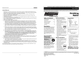
Description
Cette cloueuse de pointes est conçue pour l’assemblage de garnitures décoratives,
bandes de vitrage et petits cadres. Caractéristiques: pratique chargeur à chargement
latéral convenant pour 135 pointes, embout anti-marques, sans huile, prise confortable
de caoutchouc, fiche pivotante, pointe de contact, mécanisme auto-ajustable de
longueur de pointes et échappement ajustable.
Figure 1 - CHN71500 Cloueuse de pointes

Importantes Instructions De Sécurité
Instructions Portant Sur Un Risque d’Incendie, Un Choc Électrique Ou Des
Blessures Aux Personnes
Ce manuel contient des informations concernant la sécurité, le fonctionnement et
l’entretien. Si vous avez des questions, appeler le 1-800-543-6400 pour le service à la
clientèle.
En utilisant les outils, il faut suivre les précautions de base, y compris ce
qui suit :
PROPOSITION 65 DE CALIFORNIE
Ce produit ou son cordon peuvent contenir des produits chimiques
qui, de l’avis de l’État de Californie, causent le cancer et des anomalies
congénitales ou autres problèmes de reproduction. Lavez-vous les mains après la manipulation.
Vous pouvez créer de la poussière en coupant, ponçant,
perçant ou meulant les matériaux tels que le bois, la
peinture, le métal, le béton, le ciment ou autre maçonnerie. Cette poussière contient
souvent des produits chimiques reconnus pour causer le cancer, les déformations
congénitales
GÉNÉRALITÉ :
a. Pour réduire les risques de chocs électriques, d’incendie ou de
blessures aux personnes, lire toutes les instructions avant d’utiliser
l’outil. Ne pas suivre les avertissements, les dangers et les mises en
garde pourrait causer la MORT ou de GRAVES BLESSURES.
b. Se familiariser avec ce produit, ses commandes et son utilisation.
Suivez toutes les instructions. Contacter votre représentant Campbell Hausfeld si
vous avez des questions.
c. Seules les personnes familières avec ces règles d’utilisation sans danger devraient
utiliser cette unité.
Ne pas utiliser la cloueuse ni permettre qu’une autre personne l’utilise
si les avertissements ou les étiquettes d’avertissement situés sur le
chargeur et corps de la cloueuse ne sont pas lisibles.
Toujours prendre pour acquis que la cloueuse contient des clous.
Respecter l’outil comme accessoire de travail non pas un jouet. Donc
aucun jeu brutal. Toujours garder les autres personnes à une distance de sécurité de l’aire
de travail en cas de décharge accidentelle des clous. Ne pas pointer l’outil vers vous ou vers
quelqu’un d’autre qu’il y ait ou non des attaches dans la cloueuse. Le déclenchement accidentel
de la cloueuse pourrait causer la mort ou de graves blessures.
Ne pas apporter de modifications à l’outil sans d’abord obtenir
une approbation écrite de Campbell Hausfeld. N’utilisez pas une
cloueuse si les écrans ou protecteurs ont été enlevés ou altérés. Ne pas utiliser la cloueuse comme
un marteau. Cela peut entraîner des blessures ou endommager l’appareil.
Nettoyer et vérifier tous les tuyaux et raccords avant de brancher la
cloueuse au compresseur d’air. Remplacer les tuyaux ou les raccords
endommagés ou usés, sinon, le rendement et la durabilité de l’outil seront affectés.
AIRE DE TRAVAIL
a. Garder l’aire de travail propre et bien éclairée. Les établis encombrés et les coins
sombres augmentent les risques de chocs électriques, d’incendie et de blessures
aux personnes.
b. Ne pas faire fonctionner l’outil dans une atmosphère explosive comme
en présence de liquides, gaz ou poussières inflammables. L’outil peut
produire des étincelles menant à une inflammation de poussières ou de
fumées.
c. Garder les spectateurs, les enfants et les visiteurs loin en utilisant
l’outil. Les distractions peuvent faire perdre le contrôle de l’outil.
Instructions d’Utilisation et Manual de Pièces
Directives de Sécurité
Ce manuel contient de
l’information très importante qui
est fournie pour la SÉCURITÉ et
pour ÉVITER LES PROBLÈMES
D’ÉQUIPEMENT. Rechercher
les symboles suivants pour cette
information.
Danger indique
une situation
dangereuse imminente qui MÈNERA à
la mort ou à des blessures graves si elle
n’est pas évitée.
Avertissement
indique une
situation potentiellement dangereuse
qui, si elle n’est pas évitée, POURRAIT
mener à la mort ou à de graves
blessures.
Attention
indique une
situation potentiellement dangereuse
qui, si elle n’est pas évitée, PEUT mener
à des blessures mineures ou modérées.
Avis indique
de l’information
importante qui pourrait endommager
l’équipement si elle n’est pas respectée.
REMARQUE : Information qui exige
une attention spéciale.
Symboles de sécurité
Les symboles de sécurité suivants
apparaissent dans l’ensemble de
ce manuel pour vous aviser des
dangers et précautions importants
de sécurité.
Risque de
tomber
Porter une
protection
oculaire et un
masque.
Risque
d’explosion
Porter une
protection
auditive
Porter une
protection
oculaire.
Risque de
blessure
Lire le manuel
d’abord
Risque
d’incendie
Risque de choc
CHN71500
F-20
/