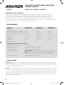
Kicker 2017 KMA Multi-Channel Amplifiers Owner's manual
- Category
- Musical Equipment
- Type
- Owner's manual

KMA150.2
KMA300.4
KMA450.6
Manual del Propietario | Español
AMPLIFICADOR DEL LA SERIE KMA
Benutzerhandbuch | Deutsch
MONOVERSTÄRKER DER KMA-SERIE
Manuel d’utilisation | Française
AMPLIFICATEUR DE SÉRIE KMA
KMA
AMPLIFIERS
Owner’s Manual
2018 KMA MultiChannel Amps Rev D.indd 12018 KMA MultiChannel Amps Rev D.indd 1 10/12/2017 5:24:15 PM10/12/2017 5:24:15 PM

2
KMA MULTI-CHANNEL SERIES AMPLIFIERS
OWNER’S MANUAL
INSTALLATION
Mounting: Choose a dry, structurally sound location to mount your KICKER amplifi er. Make sure there
are no items behind the area where the screws will be driven. Choose a location that allows at least 4”
(10cm) of open ventilation for the amplifi er. Drill four holes using a 7/64” (3mm) bit and use the supplied
#8 screws to mount the amplifi er.
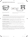
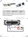
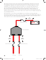
Wiring: The KMA amplifi er’s RCA inputs will receive either high or low level signals from your car stereo’s
source unit. A high-level signal can be run from the source unit’s speaker outputs to the stereo RCA input
on the end panel of the amplifi er using the KICKER KISL as shown (see page 3). Alternatively, the signal
can be delivered to the amplifi er using the low-level RCA outputs on the source unit. Keep the audio
signal cable away from factory wiring harnesses and other power wiring. If you need to cross this wiring,
cross it at a 90 degree angle.
PERFORMANCE
MODEL: KMA150.2 | KMA300.4 | KMA450.6
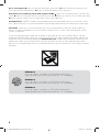
IMPORTANT SAFETY WARNING
PROLONGED CONTINUOUS OPERATION OF AN AMPLIFIER, SPEAKER, OR SUBWOOFER IN
A DISTORTED, CLIPPED OR OVER-POWERED MANNER CAN CAUSE YOUR AUDIO SYSTEM
TO OVERHEAT, POSSIBLY CATCHING FIRE AND RESULTING IN SERIOUS DAMAGE TO YOUR
COMPONENTS AND/OR VEHICLE. AMPLIFIERS REQUIRE UP TO 4 INCHES (10CM) OPEN
VENTILATION. SUBWOOFERS SHOULD BE MOUNTED WITH AT LEAST 1 INCH (2.5CM) CLEARANCE
BETWEEN THE FRONT OF THE SPEAKER AND ANY SURFACE.
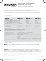
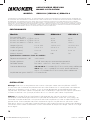
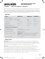
Model: KMA150.2 KMA300.4 KMA450.6
RMS Power
@ 14.4V, 4Ω stereo, ≤ 1% THD+N
@ 14.4V, 2Ω stereo, ≤ 1% THD+N
@ 14.4V, 4Ω mono, ≤ 1% THD+N
40 x 2
75 x 2
150 x 1
40 x 4
75 x 4
150 x 2
40 x 6
75 x 6
150 x 3
Length [in, cm] 8-1/16, 20.4 12-7/16, 31.5 13-15/16, 35.3
Height [in, cm] 2-5/16, 5.9 2-5/16, 5.9 2-5/16, 5.9
Width [in, cm] 7-1/8, 18 7-1/8, 18 7-1/8, 18
Remote Level No No Yes
Specifi cations common to all models:
Frequency Response ± 1dB 10Hz-20kHz
Signal-to-noise Ratio >95dB, A-weighted, re: rated power
Input Sensitivity Low: 125mV-5V, High: 250mV-10V
Electronic Crossover 150.2 & 300.4: Off, Variable HP & LP 50–200Hz, 12dB/octave slope
450.6: Amps 1 & 2 - Variable HP 0–200Hz, 12dB/octave slope;
Amp 3 - Off, Variable HP & LP 50–200Hz. 12dB/octave slope
KickEQ™ Bass Boost 0-12dB @ 40Hz (450.6 AMP 3)
2018 KMA MultiChannel Amps Rev D.indd 22018 KMA MultiChannel Amps Rev D.indd 2 10/12/2017 5:24:18 PM10/12/2017 5:24:18 PM

3
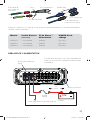
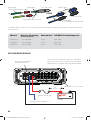
Install a fuse within 7” (18cm) of the battery and in-line with the power cable connected to your amplifi er.
source unit
high-level speaker
outputs
to amplifi er
shield
+
–
core conductor
KICKER KISL (optional)
from source unit high-
level speaker outputs
OR
to amplifi er
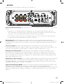
Model External Fuse
(sold separately)
Power/Ground Wire KICKER Wiring Kit
KMA150.2 1 x 40 Ampere 8 Gauge PK8, CK8
KMA300.4 1 x 60 Ampere 4 Gauge PK4, CK4
KMA450.6 1 x 80 Ampere 4 Gauge PK4, CK4
12V
battery
external fuse
remote turn-on (see page 6)
POWER WIRING
ABYC-compliant power terminals
Amplifi er uses 304-stainless steel
screws and conformal coated PCB
for increased weather resistance
aluminum bottom
plate
≤7”
(18cm)
2018 KMA MultiChannel Amps Rev D.indd 32018 KMA MultiChannel Amps Rev D.indd 3 10/12/2017 5:24:19 PM10/12/2017 5:24:19 PM

4
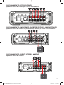
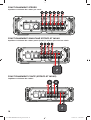
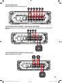
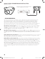
BRIDGED OPERATION (STEREO & MONO)
minimum impedance of 4 ohms
STEREO OPERATION
minimum impedance of 2 ohm
STEREO-AND-MONO-SIMULTANEOUSLY OPERATION
minimum impedance of 4 ohms bridged (mono) and 2 ohm per channel stereo
(KMA450.6 shown)
2018 KMA MultiChannel Amps Rev D.indd 42018 KMA MultiChannel Amps Rev D.indd 4 10/12/2017 5:24:19 PM10/12/2017 5:24:19 PM

5
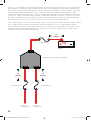
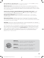
For multiple amplifi er installations where distribution blocks are used, each amplifi er should have its
proper-rated fuse, or breaker, installed between the amplifi er and the distribution block within seven inches
of the block, or on the distribution block if it provides for fusing. The primary power wire should also be
fused between the battery and distribution block, within seven inches of the battery’s B+ terminal, with
a fuse or breaker rated at least to the sum of the individual amplifi er’s fuse values, but not to exceed
1.5-times the sum of the individual fuse values (not to exceed the ampacity of the thermal insulation of the
wiring as shown in U.S.C.G. CFR33 183.425, Table 5). See the diagram below.
NOTE: Seven inches is the standard distance under U.S. Coast Guard CFR33 for placement of fuses or
breakers as required by law for new boat manufacturing. We recommend trying to adhere to this standard
in a consumer installation. Failure to do so does not mean you are breaking the law, but it does put the
safety of your boat and passengers at risk in the event of a power wire short circuit.
KICKER will now provide a three-year warranty with all KXA-
Series Amplifi er purchases paired with a qualifying KICKER
Installation Kit* .
This extends the standard warranty by an additional year. Amplifi er and Kit must be
purchased from an Authorized KICKER Dealer.
KICKER KMA amplifi er success is currently at an unheard-of rate, making the extended
warranty program even more benefi cial to you.
Using poor-quality, under-spec wiring kits will impede KMA amplifi er performance.
A superior-quality KICKER installation Kit is guaranteed to extend the life of KMA amplifi ers.
The new extended warranty applies only to KICKER amplifi ers and accessories sold to consumers by Authorized
KICKER Dealers in the United States of America or its possessions. It also only applies to the original purchaser
of KICKER amplifi ers and accessories. One warranty extension per amplifi er is allowed regardless of the number
of amplifi er installation kits purchased. This program does not apply to “B”-stock product or factory-refurbished
product.
This offer is for a limited time, so see your local Authorized KICKER Dealer soon for details.
*U.S.A. Only | EE.UU. solamente | Nur USA | Les USA Seulement
12V
external
fuse
to amplifi er
to amplifi er
≤7”
(18cm)
external
fuse
≤7”
(18cm)
external
fuse
power distribution block
battery
≤7”
(18cm)
2018 KMA MultiChannel Amps Rev D.indd 52018 KMA MultiChannel Amps Rev D.indd 5 10/12/2017 5:24:21 PM10/12/2017 5:24:21 PM

6
OPERATION
Automatic Turn-On Selection: The KMA series offers two different automatic turn-on modes that can
be selected on the end panel; +12V and DC Offset. Using the DC Offset mode causes the REM wire to
have +12V out for turning on additional amplifi ers.
• Remote Turn-On: Set the switch to +12V to use the remote turn-on lead from your source unit. Run
18 gauge wire from the Remote Turn-On Lead on your source unit to the blue REM wire on KEY
amplifi er’s wiring harness. This is the preferred automatic turn-on method.
• If 12V remote turn-on is not available, DC Offset turn-on can be used if speaker-level (high-level)
audio inputs are being used. The DC offset mode detects a 6V DC offset on the speaker wires when
the source unit has been turned on.
Input Level: The RCA inputs on KICKER KMA amplifi ers are capable of receiving either Hi or Low-level
signals from your source unit. If you are using a Hi-Level signal, simply press in the Input Level switch on
the amplifi er. Refer to the wiring section of this manual for additional instructions.
Crossover Control: The variable crossover on the side of the amplifi er allows you to adjust the
crossover frequency of AMP3 (KMA450.6 only) to OFF, hi-pass, or lo-pass from 50–200Hz, and the hi-
pass crossover frequency of AMP1 & AMP2 from OFF-200Hz. OFF will pass a full-range signal, HI will cut
off frequencies below a threshold, and LO will cut off frequencies above a threshold.
Input Gain Control: The input gain control is not a volume control. It matches the output of the source
unit to the input level of the amplifi er. Turn the source unit up to about 3/4 volume (if the source unit goes
to 30, turn it to 25). Next, slowly turn (clockwise) the gain on the amplifi er up until you can hear audible
distortion, then turn it down a little.
Bass Boost Control: The variable bass boost control on the side of the amplifi er is designed to give you
increased output, 0–12dB, at 40Hz. The setting for this control is subjective. If you turn it up, you must
readjust the input gain control to avoid clipping the amplifi er.
Remote Level KMARC (KMA450.6): With the included KMARC remote level control, you have the
ability to control the output level of the amplifi er remotely. To surface-mount the KMARC remote level
control, simply screw the remote to the chosen location, then run the cable from the controller to the
“Remote” jack on the amplifi er panel. See page 7 for installation.
REMOTE LEVEL not available with KMA150.2 and KMA300.4
2018 KMA MultiChannel Amps Rev D.indd 62018 KMA MultiChannel Amps Rev D.indd 6 10/12/2017 5:24:21 PM10/12/2017 5:24:21 PM

7
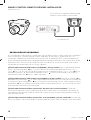
KMARC REMOTE LEVEL INSTALLATION
KMA450.6 only
Surface-mount the KMARC
remote using the supplied screws.
Connect the cable to the KMARC remote and the Remote
connection on the amplifi er
back view
Remote cable passes audio; do
not run cable parallel to power
wires.
TROUBLESHOOTING
If your amplifi er does not appear to be working, check the obvious things fi rst such as blown fuses, poor
or incorrect wiring connections, incorrect setting of crossover switch and gain controls, etc. There are
Power (PWR) & Protection (PRT) LEDs on the side panel of your Kicker KMA series amplifi er. Depending
on the state of the amplifi er and the vehicle’s charging system, the LEDs will glow either green or red.
When the green LED is lit, this indicates the amplifi er is turned on and no trouble exists.
Green LED off, no output? With a Volt Ohm Meter (VOM) check the following:
+12 volt power
terminal (should read +12V to +16V)
Remote turn-on terminal (should read +12V to +16V)
Check
for reversed power and ground connections
Ground terminal, for proper conductivity.
Green LED on, no output? Check the following:
RCA connections
Test speaker outputs with a
“known” good speaker.
Substitute source unit with a “known” good source unit.
Check for a signal
in the RCA cable feeding the amplifi er with the VOM meter set to measure “AC” voltage.
Red LED fl ickering with loud music? The red LED indicates low battery voltage. Check all the
connections in your boat’s charging system. It may be necessary to replace or charge your battery or
replace your alternator.
Red LED on, no output?
Amplifi er is very hot = thermal protection is engaged. Test for proper
impedance at the speaker terminals with a VOM meter (see the diagrams in this manual for minimum
recommended impedance and multiple speaker wiring suggestions). Also check for adequate airfl ow
around the amplifi er.
Amplifi er shuts down only while your boat is running = voltage protection circuitry
is engaged. Voltage to the amplifi er is not within the 10–16 volt operating range. Have the boat’s charging
and electrical system inspected.
Amplifi er will only play at low volume levels = short circuit protection
is engaged. Check for speaker wires shorted to each other. Check for damaged speakers or speaker(s)
operating below the minimum recommended impedance.
2018 KMA MultiChannel Amps Rev D.indd 72018 KMA MultiChannel Amps Rev D.indd 7 10/12/2017 5:24:21 PM10/12/2017 5:24:21 PM

8
No or low output?
Check the balance control on source unit
Check the RCA (or speaker input)
and speaker output connections.
Check for reversed polarity at the speaker(s)
Alternator noise-whining sound with engine’s RPM?
Check for damaged RCA (or speaker input)
cable
Check the routing of RCA (or speaker input) cable
Check the source unit for proper grounding
Check the gain settings and turn them down if they are set too high.
Ground Noise? KICKER amplifi ers are engineered to be fully compatible with all manufacturers’ head
units. Some head units may require additional grounding to prevent noise from entering the audio signal.
CAUTION: When jump starting the battery, be sure that connections made with jumper cables are
correct. Improper connections can result in blown amplifi er fuses as well as the failure of other critical
systems in the boat.
If you have more questions about the installation or operation of your new KICKER product, see the
Authorized KICKER Dealer where you made your purchase. For more advice on installation, click on the
SUPPORT tab on the KICKER homepage, www.kicker.com. Choose the TECHNICAL SUPPORT tab,
choose the subject you are interested in, and then download or view the corresponding information.
Please E-mail support@kicker.com or call Technical Services (405) 624-8583 for unanswered or specifi c
questions.
KMA150.2
40 x 2 @ 4 ohms, 14.4VDC, 1% THD, CEA-2006B (Watts)
Signal to Noise Ratio -75dB CEA-2006B (ref: 1W, A-weighted)
KMA300.4
40 x 4 @ 4 ohms, 14.4VDC, 1% THD, CEA-2006B (Watts)
Signal to Noise Ratio -75dB CEA-2006B (ref: 1W, A-weighted)
KMA450.6
40 x 6 @ 4 ohms, 14.4VDC, 1% THD, CEA-2006B (Watts)
Signal to Noise Ratio -75dB CEA-2006B (ref: 1W, A-weighted)
2018 KMA MultiChannel Amps Rev D.indd 82018 KMA MultiChannel Amps Rev D.indd 8 10/12/2017 5:24:22 PM10/12/2017 5:24:22 PM

9
Modelo: KMA150.2 KMA300.4 KMA450.6
Potencia RMS [Vatios]
a 14.4V, 4 stereo, ≤ 1% THD+N
a 14.4V, 2 stereo, ≤ 1% THD+N
a 14.4V, 4 mono, ≤ 1% THD+N
40 x 2
75 x 2
150 x 1
40 x 4
75 x 4
150 x 2
40 x 6
75 x 6
150 x 3
Longitud [pulg, cm] 8-1/16, 20.4 12-7/16, 31.5 13-15/16, 35.3
Altura [pulg, cm] 2-5/16, 5.9 2-5/16, 5.9 2-5/16, 5.9
Ancho [pulg, cm] 7-1/8, 18 7-1/8, 18 7-1/8, 18
Control remoto nivel No No Si
Especifi caciones comunes para todos los modelos:
Respuesta de frecuencia ± 1dB 10Hz–20kHz
Relación señal-ruido [dB] >95dB, ponderación A, re: potencia nominal
Sensibilidad de entrada Bajo: 125mV-5V, Alto: 250mV–10V
Divisor de frecuencias electrónico
seleccionable
150.2 & 300.4: Off, variables HP & LP 50–200Hz, 12dB/pendiente
de octava
450.6: Amps 1 & 2 - variables HP 0–200Hz, 12dB/pendiente de
octava;
Amp 3 - Off, Variable HP & LP 50–200Hz, 12dB/pendiente de octava
Refuerzo de graves KickEQ™ Boost - 0-12dB @ 40Hz
ADVERTENCIA IMPORTANTE DE SEGURIDAD: LA OPERACIÓN PROLONGADA Y CONTINUA DE UN AMPLIFICADOR DE MANERA
DISTORSIONADA O CORTADA PUEDE PROVOCAR QUE SU SISTEMA DE AUDIO SE SOBRECALIENTE CON LA POSIBILIDAD DE
INCENDIARSE Y PROVOCAR DAÑOS GRAVES A SUS COMPONENTES O VEHÍCULO. ¡LOS PRODUCTOS KICKER PUEDEN PRODUCIR
NIVELES DE SONIDO QUE PUEDEN DAÑAR PERMANENTEMENTE SU OÍDO! SUBIR EL VOLUMEN DE UN SISTEMA A UN NIVEL EN EL
CUAL SE ESCUCHA UNA DISTORSIÓN ES MÁS DAÑINO PARA SUS OÍDOS QUE ESCUCHAR UN SISTEMA SIN DISTORSIÓN AL MISMO
NIVEL DE VOLUMEN. EL UMBRAL DEL DOLOR ES SIEMPRE UN INDICADOR DE QUE EL NIVEL DEL SONIDO ES MUY ALTO Y PUEDE
DAÑAR PERMANENTEMENTE SU AUDICIÓN. USE EL SENTIDO COMÚN AL CONTROLAR EL VOLUMEN.
AMPLIFICADOR DE LA SERIE KMA.1
MANUAL DEL PROPIETARIO
INSTALACIÓN
Montaje: Escoja un lugar estructuralmente sólido para montar el amplifi cador KICKER. Asegúrese de
que no haya nada por detrás de dónde van a entrar los tornillos. Escoja un lugar en que queden por lo
menos 4 plg. (10 cm) de espacio abierto de ventilación alrededor del amplifi cador. Si es posible, monte el
amplifi cador en el compartimiento de pasajeros, con ambiente acondicionado. Haga cuatro agujeros con
una broca de 7/64 de plg. (3 mm) y monte el amplifi cador con los tornillos N° 8 que se suministran.
Cableado: Las entradas RCA del amplifi cador KMA recibirán señales de alto o bajo nivel desde la unidad
fuente del estéreo de su automóvil. Una señal de alto nivel se puede transmitir desde las salidas de los
altavoces de la unidad fuente hasta la entrada RCA del estéreo en el panel inferior del amplifi cador utilizando
el KICKER KISL, como se muestra en la imagen. Alternativamente, la señal se puede transmitir hacia el
amplifi cador utilizando las salidas RCA de bajo nivel en la unidad fuente. Mantenga el cable de señal de
audio lejos de los arneses de cableado de fábrica y de otros cables eléctricos. Si necesita cruzar este
cableado, hágalo a un ángulo de 90 grados.
RENDIMIENTO
MODELOS: KMA150.2 | KMA300.4 | KMA450.6
2018 KMA MultiChannel Amps Rev D.indd 92018 KMA MultiChannel Amps Rev D.indd 9 10/12/2017 5:24:22 PM10/12/2017 5:24:22 PM

10
12V
batería
fusible externo
encendido a distancia (página 15)
CABLEADO DE ALIMENTACIÓN
Placa con fondo
de aluminio
El amplifi cador utiliza tornillos de acero
inoxidable tipo 304 y placa de circuito
impreso con recubrimiento conformado
para una mayor resistencia al clima.
Terminales de energía
aprobados por ABYC
≤7”
(18cm)
Modelo Fusible Externo
(no incluido)
Cable de Alimentación y
Conexión a Tierra
Kit de cableado
KICKER
KMA150.2 1 x 40 Ampere Calibre 8 PK8, CK8
KMA300.4 1 x 60 Ampere Calibre 4 PK4, CK4
KMA450.6 1 x 80 Ampere Calibre 4 PK4, CK4
Cable de salida
de altavoz de
alto nivel
Hacia el amplifi cador
Hacia el
amplifi cador
Conexión a tierra o blindaje
+
–
cable central
Instale un fusible a menos de 7 plg. (18 cm) de la batería y en línea con el cable de alimentación
conectado al amplifi cador.
KICKER KISL
Cable de salida de
altavoz de alto nivel
O
2018 KMA MultiChannel Amps Rev D.indd 102018 KMA MultiChannel Amps Rev D.indd 10 10/12/2017 5:24:22 PM10/12/2017 5:24:22 PM

11
FUNCIONAMIENTO PUENTE (STEREO & MONO)
impedancia mínima de 4 ohmios
FUNCIONAMIENTO ESTEREOFÓNICO
impedancia mínima de 2 ohmio por canal en estereofónico
FUNCIONAMIENTO SIMULTÁNEO EN ESTEREOFÓNICO Y MONOFÓNICO
impedancia mínima de 4 ohmios en puente (mono) y 2 ohmio por canal en estereofónico
2018 KMA MultiChannel Amps Rev D.indd 112018 KMA MultiChannel Amps Rev D.indd 11 10/12/2017 5:24:22 PM10/12/2017 5:24:22 PM

12
Para varias instalaciones de amplifi cadores donde se utilizan bloques de distribución, cada amplifi cador
debe poseer su fusible de grado apropiado, o interruptor, instalado entre el amplifi cador y el bloque de
distribución a siete pulgadas del bloque, o sobre el bloque de distribución si admite fusibles. El principal
cable de alimentación también debe fusionarse entre la batería y el bloque de distribución, a siete
pulgadas del terminal B+ de la batería, con un fusible o interruptor con una clasifi cación al menos de la
suma de los valores individuales del fusible del amplifi cador, pero que no supere 1,5 veces la suma de
los valores individuales del fusible (que no supere la ampacidad del aislamiento térmico del cableado
como se demuestra en U.S.C.G. CFR33 183.425, Tabla 5). Vea el siguiente diagrama.
NOTA: Siete pulgadas es la distancia estándar según la Guardia Costera de los Estados Unidos, CFR33,
para la colocación de fusibles o interruptores como lo requiere la ley para la fabricación de nuevos
barcos. Recomendamos cumplir con este estándar en caso de ser instalado por el consumidor. El no
hacerlo no signifi ca que no cumple con la ley, pero pone en riesgo la seguridad de su barco y de los
pasajeros en caso de cortocircuito eléctrico.
12V
fusible externo
Hacia el
amplifi cador
Hacia el
amplifi cador
≤7”
(18cm)
fusible externo
≤7”
(18cm)
≤7”
(18cm)
fusible externo
Bloqueo de distribución de energía
batería
2018 KMA MultiChannel Amps Rev D.indd 122018 KMA MultiChannel Amps Rev D.indd 12 10/12/2017 5:24:24 PM10/12/2017 5:24:24 PM

13
FUNCIONAMIENTO
Selección de Encendido Automático: La serie KMA ofrece dos modalidades de encendido automático
que: +12V, y compensación de CC.
• Encendido a Distancia: Instale cable calibre 18 desde el conductor de encendido a distancia de la
unidad fuente hasta la terminal etiquetada REM entre las terminales de alimentación positiva y negativa
del amplifi cador.
• Encendido por Compensación de CC: En la modalidad de compensación de CC, el amplifi cador
detecta una subida de 6V de las salidas de altavoz de alto nivel cuando la unidad fuente se ha
encendido.
Nivel de Entrada: Las entradas RCA de los amplifi cadores KMA de KICKER aceptan señales de bajo
nivel o alto nivel procedentes de la unidad fuente. Si la única salida disponible de la unidad fuente es una
señal de alto nivel, oprima y deje adentro el selector de nivel de entrada del amplifi cador. En la sección de
cableado de este manual hay más instrucciones.
Control de Crossover: El crossover variable ubicado en la parte de arriba del le permite ajustar la
frecuencia de paso bajo/alto crossover desde AMP3 OFF a 200Hz (KMA450.6) y la frecuencia de paso alto
de AMP1 & AMP2 de OFF a 200Hz.
Control de Amplifi cación de Entrada: El control de amplifi cación de entrada no es un control de
volumen. El control de amplifi cación de entrada hace que la salida de la fuente corresponda al nivel de
entrada del amplifi cador. Suba el volumen de la unidad fuente a ¾ (si la unidad llega a 30, súbale el
volumen a 25). A continuación, suba lentamente la amplifi cación (girando el control en el sentido de las
manecillas del reloj) hasta que pueda oír distorsión, luego bájela un poquito.
Refuerzo de Bajos: El control de potenciador de graves variable a un costado del amplifi cador está
diseñado para ofrecer una salida incrementada, 0–12dB, a 40Hz. La confi guración para este control
es subjetiva. Si la aumenta, puede reajustar el control de ganancia de entrada para evitar recortar el
amplifi cador.
Control Remoto de Nivel-KMARC (KMA450.6): Con el control remoto de nivel KMARC opcional,
puede controlar a distancia el nivel de salida del amplifi cador. Para instalar en superfi cie el control remoto
de nivel KMARC, simplemente atornille el control en la ubicación elegida, luego extienda el cable del
controlador hacia la entrada “Remote” en el panel del amplifi cador. Consulte la página 14.
Nivel remoto no disponible con KMA150.2 y KMA300.4
2018 KMA MultiChannel Amps Rev D.indd 132018 KMA MultiChannel Amps Rev D.indd 13 10/12/2017 5:24:24 PM10/12/2017 5:24:24 PM

14
RESOLUCIÓN DE PROBLEMAS
Si su amplifi cador parece no estar funcionando, revise lo obvio primero: fusibles quemados, conexiones
malas o incorrectas, posición incorrecta de los selectores de crossover y amplifi cación, etc. Su
amplifi cador modelo KMA de KICKER cuenta con los LED de protección (PRT) y de encendido (PWR)
en el panel de alimentación lateral. Dependiendo del estado del amplifi cador y del sistema de carga del
vehículo, los LED se iluminarán en verde o en rojo. Cuando el LED se ilumina en verde, indica que el
amplifi cador está encendido y no hay ningún problema.
¿El indicador luminoso LED verde está apagado y no hay salida? Con un voltímetro/ohmímetro
(VOM), verifi que lo siguiente:
Hay +12V en la terminal de alimentación (debe leerse entre +12V y
+16V).
Hay +12V en la terminal de encendido a distancia (debe leerse entre +12V y +16V).
No hay
conexiones invertidas de alimentación o conexión a tierra.
La terminal de conexión a tierra tiene la
conductividad adecuada.
No hay fusibles quemados.
¿El Indicador luminoso LED verde está encendido y no hay salida? Verifi que lo siguiente:
Las
conexiones RCA están bien.
Las salidas de altavoces están bien pues han sido puestas a prueba con
un altavoz en buenas condiciones.
Se ha cambiado la unidad fuente por una unidad fuente en buenas
condiciones.
Con un medidor VOM confi gurado para medir voltaje de “CA”, se ha buscado una señal
en el cable RCA que alimenta el amplifi cador.
¿El indicador luminoso LED de “protection” destella con la música fuerte? El indicador
luminoso LED rojo indica que hay bajo voltaje de batería. Revise todas las conexiones del sistema de
carga eléctrica del vehículo. Puede ser necesario cambiar o cargar la batería del vehículo o cambiar el
alternador del vehículo.
¿El indicador luminoso LED de “protection” está encendido y no hay salida?
El amplifi cador
está muy caliente = Se ha activado el circuito de protección térmica. Con un medidor VOM, compruebe
KMARC CONTROL REMOTO DE NIVEL INSTALACIÓN
(KMA450.6 sólo)
vista desde atrás
Para instalar en superfi cie el control remoto
KMARC use los tornillos suministrados.
2018 KMA MultiChannel Amps Rev D.indd 142018 KMA MultiChannel Amps Rev D.indd 14 10/12/2017 5:24:24 PM10/12/2017 5:24:24 PM

15
KMA150.2
40 x 2 @ 4 ohmios, 14.4VCC, 1% THD, CEA-2006B (W)
Relación de Señal a Ruido -75dB CEA-2006 (ref: 1W, ponderado en A)
KMA300.4
40 x 4 @ 4 ohmios, 14.4VCC, 1% THD, CEA-2006B (W)
Relación de Señal a Ruido -75dB CEA-2006 (ref: 1W, ponderado en A)
KMA450.6
40 x 6 @ 4 ohmios, 14.4VCC, 1% THD, CEA-2006B (W)
Relación de Señal a Ruido -75dB CEA-2006 (ref: 1W, ponderado en A)
que las terminales de altavoz tengan la impedancia correcta (vea en este manual los diagramas que
contienen datos de impedancia mínima recomendada y sugerencias de cableado de varios altavoces).
Asegúrese también de que haya un fl ujo de aire adecuado alrededor del amplifi cador.
El amplifi cador
se apaga sólo cuando el vehículo está en marcha = Se ha activado el circuito de protección contra
sobrevoltaje. El voltaje al amplifi cador no está dentro del intervalo de funcionamiento de 10V a 16V. Haga
inspeccionar el sistema eléctrico y de carga eléctrica del automóvil.
El amplifi cador sólo funciona a bajo
volumen = Se ha activado el circuito de protección contra cortocircuitos. Asegúrese de que los cables de
los altavoces no estén en cortocircuito entre sí o con el chasis del vehículo. Vea si hay altavoces dañados
o funcionando a menos de la impedancia mínima recomendada.
¿No hay salida de uno de los canales?
Revise el control de balance de la unidad fuente.
Revise
las conexiones RCA (o de entrada de altavoz) y de salida de altavoz del canal.
¿Hay ruido sibilante de alternador asociado a las RPM del motor?
Vea si hay algún cable RCA
(o de entrada de altavoz) dañado.
Revise el encaminamiento del cable RCA (o de entrada de altavoz).
Vea si la unidad fuente tiene conexión a tierra apropiada.
Revise las confi guraciones de amplifi cación
y bájelas si están muy altas.
¿Hay baja respuesta de bajos? Invierta la conexión de uno de los altavoces de positiva a negativa en
los canales estereofónicos y/o de subwoofer; si los bajos mejoran, el altavoz estaba fuera de fase.
¿Hay ruido de conexión a tierra? Los amplifi cadores KICKER son totalmente compatibles con las
unidades fuente de todos los fabricantes. Algunas unidades principales pueden necesitar más conexión
a tierra para evitar que entre ruido a la señal de audio. En la mayoría de los casos, este problema con la
unidad principal se resuelve instalando un cable de conexión a tierra desde las salidas RCA de la unidad
principal al chasis.
PRECAUCIÓN: Cuando haga arrancar el vehículo con cables de arranque conectados a una batería
externa, asegúrese de que las conexiones de los cables de arranque sean correctas. Conectar los
cables de arranque de manera incorrecta puede quemar los fusibles del amplifi cador y causar fallas en
otros sistemas del vehículo.
Si tiene más preguntas sobre la instalación de su nuevo producto KICKER, vaya al distribuidor autorizado
de KICKER donde lo compró. Si necesita más consejos sobre la instalación, haga clic en la lengüeta
SUPPORT (apoyo) de la página Web de KICKER, www.KICKER.com. Escoja la lengüeta TECHNICAL
SUPPORT (apoyo técnico), escoja el tema que le interese y luego descargue o vea la información
correspondiente. Envíe un mensaje por correo electrónico a [email protected] o comuníquese con
Servicios Técnicos llamando al (405) 624-8583 si tiene preguntas específi cas o a las cuales no haya
encontrado respuesta.
2018 KMA MultiChannel Amps Rev D.indd 152018 KMA MultiChannel Amps Rev D.indd 15 10/12/2017 5:24:25 PM10/12/2017 5:24:25 PM

16
Modèle: KMA150.2 KMA300.4 KMA450.6
Puissance RMS, Watts
@ 14,4V, 4 stereo, ≤1 % THD+N
@ 14,4V, 2 stereo, ≤1 % THD+N
@ 14,4V, 4 mono, ≤1 % THD+N
40 x 2
75 x 2
150 x 1
40 x 4
75 x 4
150 x 2
40 x 6
75 x 6
150 x 3
Longueur [po, cm] 8-1/16, 20,4 12-7/16, 31,5 13-15/16, 35,3
Hauteur en [po cm] 2-5/16, 5,9 2-5/16, 5,9 2-5/16, 5,9
Largeur en [po cm] 7-1/8, 18 7-1/8, 18 7-1/8, 18
Niveau à distance : Non Non Oui
Spécifi cations communes à tous les modèles :
Réponse de fréquence ± 1 dB 10Hz à 20kHz
Rapport signal/bruit > 95 dB, niveau de puissance acoustique pondéré A
Sensibilité d'entrée Bas niveau : 125mV–5V ; Haut niveau : 250mV–10V
Crossover électronique 150.2 & 300.4: Off, Variable HP & LP 50 à 200Hz, pente 12dB/octave
450.6: Amps 1 & 2 - Variable HP 0 à 200Hz, pente 12dB/octave;
Amp 3 - Off, Variable HP & LP 50 à 200Hz, pente 12dB/octave
Amplifi cation des graves KickEQ™ 0 à 12 db @ 40Hz
AMPLIFICATEUR SÉRIE KMA
MANUEL D’UTILISATION
INSTALLATION
Montage: Choisissez un emplacement de structure saine pour monter votre amplifi cateur KICKER.
Assurez-vous que l’arrière de l’emplacement où vous allez enfoncer les vis ne comporte aucun élément.
Choisissez un endroit assurant au moins 10 cm (4 po) de dégagement de ventilation ouverte pour
l’amplifi cateur. Si possible, montez l’amplifi cateur dans l’habitacle passager climatisé. Percez quatre trous
à l’aide d’un foret de 3 mm (7/64 po) et utilisez les vis nº 8 fournies pour monter l’amplifi cateur.
Câblage: Les entrées RCA de l’amplifi cateur KMA recevront des signaux haut ou bas niveau en
provenance d’autoradio de votre voiture. Il est possible de connecter les sorties des haut-parleurs de
l’autoradio à l’entrée stéréo RCA sur le panneau latéral de l’amplifi cateur à l’aide du câble KICKER KISL,
comme illustré. Une autre option consiste à connecter le signal à l’amplifi cateur en utilisant les sorties
RCA de bas niveau sur l’autoradio. Gardez le câble du signal audio à distance du faisceau de câblage en
usine et des autres câbles d’alimentation. Si vous avez besoin de couper ce câblage, faites-le à un angle
de 90 degrés.
PERFORMANCES
MODÈLE: KMA150.2 | KMA300.4 | KMA450.6
AVERTISSEMENT DE SÉCURITÉ IMPORTANT: UN FONCTIONNEMENT CONTINU ET PROLONGÉ D’UN AMPLIFICATEUR EN DISTORSION OU
EN SATURATION PEUT PROVOQUER LA SURCHAUFFE DE VOTRE SYSTÈME AUDIO, UN POTENTIEL DÉPART D’INCENDIE ET SÉRIEUSEMENT
ENDOMMAGER VOS COMPOSANTS ET/OU VOTRE VÉHICULE. LES PRODUITS KICKER PEUVENT PRODUIRE DES NIVEAUX SONORES
SUSCEPTIBLES D’ENDOMMAGER L’OUÏE DE FAÇON IRRÉVERSIBLE! L’AUGMENTATION DU VOLUME D’UN SYSTÈME JUSQU’À UN NIVEAU
PRÉSENTANT UNE DISTORSION AUDIBLE ENDOMMAGE DAVANTAGE L’OUÏE QUE L’ÉCOUTE D’UN SYSTÈME SANS DISTORSION AU MÊME
VOLUME. LE SEUIL DE LA DOULEUR EST TOUJOURS LE SIGNE QUE LE NIVEAU SONORE EST TROP ÉLEVÉ ET RISQUE D’ENDOMMAGER
L’OUÏE DE FAÇON IRRÉVERSIBLE. RÉGLEZ LE VOLUME EN FAISANT PREUVE DE BON SENS.
2018 KMA MultiChannel Amps Rev D.indd 162018 KMA MultiChannel Amps Rev D.indd 16 10/12/2017 5:24:25 PM10/12/2017 5:24:25 PM

17
CÂBLAGE DE L’ALIMENTATION
12V
Batterie
Mise sous tension à distance (page 20)
Fusible
Externe
terminaisons conformes
ABYC
L’amplifi cateur utilise des vis en acier inoxydable 304
et des circuits imprimés à revêtement conforme pour
une meilleure
base en aluminium
≤7”
(18cm)
Fil de sortie de
haut-parleur de
haut niveau
Fil de sortie de haut-
parleur de haut niveau
Vers l’amplifi cateur
Masse ou blindage
+
–
Âme
Installez un fusible dans un rayon de 18 cm (7 po) de la batterie directement sur le câble d’alimentation
raccordé à votre amplifi cateur.
KICKER KISL
OU
Vers l’amplifi cateur
Modèle Fusible Externe
(non inclus)
Fil de Masse /
Alimentation
KICKER Kit de
câblage
KMA150.2 1 x 40 Ampere Calibre 8 PK8, CK8
KMA300.4 1 x 60 Ampere Calibre 4 PK4, CK4
KMA450.6 1 x 80 Ampères Calibre 4 PK4, CK4
2018 KMA MultiChannel Amps Rev D.indd 172018 KMA MultiChannel Amps Rev D.indd 17 10/12/2017 5:24:25 PM10/12/2017 5:24:25 PM

18
FONCTIONNEMENT PONTÉ (STÉRÉO ET MONO)
impédance minimum de 4 ohms
FONCTIONNEMENT STÉRÉO
impédance minimum de 2 ohms par canal
FONCTIONNEMENT SIMULTANÉ STÉRÉO ET MONO
impédance minimum de 4 ohms ponte (mono) et 2 ohms par canal en stéréo
2018 KMA MultiChannel Amps Rev D.indd 182018 KMA MultiChannel Amps Rev D.indd 18 10/12/2017 5:24:25 PM10/12/2017 5:24:25 PM

19
12V
Vers
l’amplifi cateur
Vers
l’amplifi cateur
Fusible
Externe
Fusible
Externe
≤7”
(18cm)
≤7”
(18cm)
Fusible Externe
répartiteur de puissance
Batterie
≤7”
(18cm)
Pour des installations à plusieurs amplifi cateurs où des répartiteurs sont mis en œuvre, chaque
amplifi cateur doit avoir son propre fusible correctement calibré, ou un coupe-circuit, installé entre
l’amplifi cateur et le répartiteur à moins de 18 cm du répartiteur ou sur le répartiteur lui-même s’il sert
de fusible. Un fusible doit aussi être installé sur le câble d’alimentation principal entre la batterie et le
répartiteur, à moins de 18 cm (sept pouces) de la borne B+ de la batterie, avec un fusible ou un coupe-
circuit de calibre au moins égal à la somme des valeurs individuelles des fusibles de l’amplifi cateur, mais
ne dépassant pas 1,5 fois la somme des valeurs individuelles des fusibles (sans dépasser l’intensité
électrique de l’isolation thermique du câblage comme présenté dans le tableau 5 de la norme U.S.C.G.
CFR33 183.425). Voir le diagramme ci-dessous.
NOTE : 18 cm (sept pouces) est la distance standard selon la norme U.S. Coast Guard CFR33 pour
l’installation de fusibles ou coupe-circuit imposée par la loi pour la construction de bateaux neufs.
Nous vous recommandons de suivre cette norme dans les installations grand public. Ne pas la suivre
ne constitue pas une infraction à la loi, mais met en risque la sécurité de votre embarcation et de vos
passagers en cas de court-circuit électrique.
2018 KMA MultiChannel Amps Rev D.indd 192018 KMA MultiChannel Amps Rev D.indd 19 10/12/2017 5:24:27 PM10/12/2017 5:24:27 PM

20
UTILISATION
Sélection de Mise sous Tension Automatique : La série KMA propose deux modes d’allumage
automatique différents ; +12 V et décalage en continu.
• Mise sous Tension à Distance : Faites passer un fi l de calibre 18 à partir du fi l de mise sous tension
à distance sur votre appareil source jusqu’à la borne étiquetée REM entre la borne négative et la
borne positive d’alimentation de l’amplifi cateur. Il s’agit de la méthode préférée de mise sous tension
automatique.
• Mise sous Tension en Mode DC Offset : Le mode DC Offset détecte une surtension de 3 volts en
provenance des sorties de haut-parleur de niveau haut (HI) quand l’appareil source a été mis en
marche.
Niveau d’Entrée : Les entrées RCA sur les amplifi cateurs KICKER KMA acceptent les signaux de
niveaux haut et bas à partir de votre appareil source. Si votre appareil source n’est doté que d’une sortie
de signal haut niveau, appuyez simplement sur le commutateur de niveau d’entrée sur l’amplifi cateur. Voir
la section sur le câblage de ce manuel pour d’autres instructions.
Commande de Filtre : Le commande de fi ltre sur le côté de l’amplifi cateur vous permet d’ajuster la
fréquence du répartiteur à OFF, salut-passer et lo-pass de 50 à 200 Hz (AMP 3) et OFF à 200 Hz (AMP 1 &
2). Les paramètres de ces commandes sont subjectifs ; 80 Hz constitue une bonne valeur de départ.
Commande du Gain d’Entrée : La commande du gain d’entrée n’est pas une commande de volume.
Elle fait correspondre la sortie de l’appareil source au niveau d’entrée de l’amplifi cateur. Réglez l’appareil
source à environ ¾ du volume (si le réglage de l’appareil source va jusqu’à 30, réglez à 25). Ensuite,
augmentez lentement le gain de l’amplifi cateur en faisant tourner le bouton (dans le sens des aiguilles
d’une montre) jusqu’à produire une distorsion audible, puis baissez un peu le gain.
Commande de l’Augmentation des Graves : La télécommande de l’amplifi cateur de basses
fréquences sur le côté de l’amplifi cateur est conçue pour vous donner un meilleur son, de 0 à 12 dB,
à 40 Hz. Le paramétrage de cette commande est subjectif. Si vous le mettez en marche, vous devrez
réajuster la télécommande de gain pour éviter de perturber l’amplifi cateur.
Télécommande du Niveau-KMARC (KMA450.6) : Grâce à la télécommande de niveau KMARC
facultative, vous avez la capacité de contrôler le niveau d’sortie de votre amplifi cateur à distance. Pour
une installation en surface de la télécommande de niveau KMARC, vissez simplement la télécommande à
l’emplacement choisi, acheminez ensuite le câble du contrôleur vers la prise « à distance » sur le panneau
de commande de l’amplifi cateur. Voir la page 21.
Niveau à distance indisponible avec KMA150.2 et KMA300.4
2018 KMA MultiChannel Amps Rev D.indd 202018 KMA MultiChannel Amps Rev D.indd 20 10/12/2017 5:24:27 PM10/12/2017 5:24:27 PM
Page is loading ...
Page is loading ...
Page is loading ...
Page is loading ...
Page is loading ...
Page is loading ...
Page is loading ...
Page is loading ...
Page is loading ...
Page is loading ...
Page is loading ...
Page is loading ...
-
 1
1
-
 2
2
-
 3
3
-
 4
4
-
 5
5
-
 6
6
-
 7
7
-
 8
8
-
 9
9
-
 10
10
-
 11
11
-
 12
12
-
 13
13
-
 14
14
-
 15
15
-
 16
16
-
 17
17
-
 18
18
-
 19
19
-
 20
20
-
 21
21
-
 22
22
-
 23
23
-
 24
24
-
 25
25
-
 26
26
-
 27
27
-
 28
28
-
 29
29
-
 30
30
-
 31
31
-
 32
32


Kicker 2017 KMA Multi-Channel Amplifiers Owner's manual
- Category
- Musical Equipment
- Type
- Owner's manual
Ask a question and I''ll find the answer in the document
Finding information in a document is now easier with AI
in other languages
Related papers
-
Kicker KMA360.4 KMA Series 4-Channel Marine Amplifier Owner's manual
-
-
-
Kicker BX360.4 Owner's manual
-
Kicker CX600.1 Owner's manual
-
-
-
-
-
Other documents
-
 EnrockAudio EAKIT8G User manual
-
MTX Audio MTX MXA4002 User manual
-
Ground Zero GZIA 1.1000DXII Owner's manual
-
Rotel RB06 Owner's manual
-
RCS LSA-2000 Owner's manual
-
Magnat Audio POWER CORE TWO Owner's manual
-
 Krell Industries KMA-160 Monaural User manual
-
Triangle Altea Owner's manual
-
Magnat Edition Two Limited Owner's manual
-
Magnat Audio Power Core One Limited Owner's manual

