Page is loading ...

W-HHT-5000/6000/8000/10000/12000 Series
3-Phase Hybrid Storage Inverter
USER MANUAL
V1.00

CONTENTS
1. INTRODUCTION ................................................................................................................. 3
......................................... 3
1.2 Symbols on the label ........................................................................................................ 3
2. SAFETY AND WARNINGS ............................................................................................... 4
3. UNPACKING ......................................................................................................................... 6
3.1 Scope of Delivery .............................................................................................................. 6
3.2 Product Overview ............................................................................................................. 6
4. INSTALLING .......................................................................................................................... 8
4.1 Installation Requirement .................................................................................................. 8
4.2 Mounting Location ........................................................................................................... 9
4.3 Mounting ........................................................................................................................... 9
4.4 Installing the PE cable .................................................................................................... 10
5. COMMISSIONING ............................................................................................................ 11
5.1 Safety Instructions .......................................................................................................... 11
5.2 AC Wire Assembly and Connection .............................................................................. 12
5.3 Back-up Wire Assembly and Connection ..................................................................... 12
5.4 PV Wire Assembly and Connection ............................................................................... 13
5.5 Battery Wire Assembly and Connection ....................................................................... 14
5.6 Residual Current Protection ........................................................................................... 14
6. COMMUNICATION.......................................................................................................... 15
6.1 System monitoring via Wi-Fi Stick - RS485/Wi-Fi /GPRS ........................................... 15
6.2 Auto Test (ONLY for Italian Market) .............................................................................. 16
7. START UP AND OPERATION ....................................................................................... 17
7.1 Safety Check Before Start Up ......................................................................................... 17
7.2 Inverter LED Indicators ................................................................................................... 18
7.3 Display and Control Logics ............................................................................................ 19
8. DISCONNECTING FROM VOLTAGE RESOURCES ............................................... 20
9. TECHNICAL PARAMETERS ........................................................................................... 21
10. TROUBLE SHOOTING ................................................................................................ 23
11. SYSTEM MAINTENANCE .......................................................................................... 27
12. RESTARTS........................................................................................................................ 28

3 W-HHT-5000/6000/8000/10000/12000 USER MANUAL
1. INTRODUCTION
1.1 Operation modes introductionModalità di Funzionamento
W-HHT normally has the following operation modes based on your configuration
and layout conditions.
1.2 Symbols on the label
DANGER, WARNING AND
CAUTION
RECYCLABLE AND REUSABLE
HIGH VOLTAGE
AVOID CONTACT
AVOID DAMP AND MOISTURE
HIGH TEMPERATURE
AVOID CONTACT
SHIPMENT STACK LIMIT: 7

W-HHT-5000/6000/8000/10000/12000 USER MANUAL 4
CE MARKS
DO NOT DISPOSE WITH
HOUSEHOLD WASTE
PROCEED OPERATIONS
AFTER 5 MINUTES
DISCHARGE
BREAKABLE ITEM
PLACE UPWARDS
USER MANUAL IN PACK
2. SAFETY AND WARNINGS
1. All persons who are responsible for mounting, installation, commissioning,
maintenance, tests, and service of WESTERN CO inverter products must be suitably
trained and qualified for corresponding operations. They MUST be experienced and
have knowledge of operation safety and professional methods. All installation
personnel must have knowledge of all applicable safety information, standards,
directives, and regulations.
2. The product must ONLY be connected and operated with PV arrays of protection
class II, in accordance with IEC 61730, application class A. The PV modules must also
be compatible with this product. Power resources other than compatible PV arrays
MUST not be connected and operate with the product.
3. When designing or constructing a PV system, all components MUST remain in their
permitted operating ranges, and their installation requirements MUST always be
fulfilled.
4. Under exposure to sunlight, the PV array may generate dangerous output in DC
voltage. Contacts with the DC wires, conductors and live components in the inverter
may result in lethal shocks.
5. High voltages in inverter could cause lethal electrical shocks. Before proceeding any
work, including maintenance and/or service, on the inverter, fully disconnect it from
all DC input, AC grid and other voltage sources. There MUST be a 5-minute waiting
time after the full disconnection.
6. The DC input voltage of the PV array MUST never exceed the maximum input
voltage of the inverter.

5 W-HHT-5000/6000/8000/10000/12000 USER MANUAL
7. DO NOT touch parts of the inverter during operation as heat will be induced and
these parts will exceed 60.
8. There are installations where multiple inverter energy systems are used and electrical
installation connects at 3-phase points of supply to the grid, please refer to the
requirements of Appendix B.
9. Safe Transport / Handling:
- Find the mark of PLACE UPWARDS on the inverter container and keep it upward.
- The inverter container should be tied or fixed during transportation.
- The transport of the inverter requires two people for lifting, there is one handle on
the left and one on the right.
- The inverter should be protected from heavy vibrations and shocks during
transportation.
10. Compatible Battery Models
Brand
Model
Pylontech
Force-H1
Force-H2
Powercube X1
Powercube X2
Powercube H1
Powercube H2
Dyness
Tower T7/T10/T14/T17/T21
Soluna
HV PACK 10K&15K

W-HHT-5000/6000/8000/10000/12000 USER MANUAL 6
3. UNPACKING
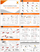
3.1 Scope of Delivery
Please inspect and check for completeness in the scope of delivery. Confirm with
purchase order.
INVERTER
MOUNTING
BRACKET
MOUNTING
ACCESSORIES
DEVALAN
DC PLUGS
(SEALED)
BAT+/-
CONNECTOR
AC GRID
CONNECTOR
1
1
1
2
1
1
BACK -UP
CONNECTOR
WI-FI STICK
METER /DRED
CONNECTOR
DOCUMENTS
CT
RJ45 ADAPTER
1
1
1
1
3
1
3.2 Product Overview
The total size of W-HHT-5000/6000/8000/10000/12000 is 425(width) 351(height)
pairs of PV input terminals, 1 pair of Battery input terminal and
2 communication ports. It also has a LED&LCD (or just LED, determined by user) for
getting information and setting parameters at field.

7 W-HHT-5000/6000/8000/10000/12000 USER MANUAL
The detail description is shown below:
Mark Num.
Component
Description
1
LED&LCD or LED
Display and setting device at field
2
DC Switch
For switch on/off the inverter
3
PV Terminal (s)
Connected with PV Panel
4
Battery Terminal
Connected with Battery
5
COM1: Wi-Fi/4G
Alternative Wireless communication
6
COM2:
BMS/CT/Meter/DRED/RS485
For CT,Meter,BMS,DRED,RS485
7
Back-up Terminal
Connected with Back-up for EPS
8
AC Terminal
Connected with AC Grid
9
Secondary PE Terminal
For Grounding Protection

W-HHT-5000/6000/8000/10000/12000 USER MANUAL 8
4. INSTALLING
4.1 Installation Requirement
1. Please install the inverter(s) in places that can avoid inadvertent contact.
2. I
dimensions.
3. Please install the inverter in an accessible location for operation, future maintenance
and service.
4. The inverter performance peaks at ambient temperature lower than 45.
5. When installing in residential or domestic environment, it is recommended to install
and mount the inverter on a solid, concrete wall surface. Mounting the inverter on
composite or plaster boards or walls with similar materials would induce noise during
its operation and is therefore not recommended.
6. DO NOT cover the inverter NOR place any objects on top of the inverter.
7. To ensure sufficient room for heat dissipation and maintenance, the clearing space
between inverter(s) and other surroundings is indicated below for reference:
8. Avoid direct exposure to sunlight and rain and snow layup.

9 W-HHT-5000/6000/8000/10000/12000 USER MANUAL
4.2 Mounting Location
1. DO NOT mount the inverter near any inflammable materials.
2. DO NOT mount the inverter near any explosive materials.
3. DO NOT mount the inverter on tilting surface over 15 backwards. Please mount the
inverter on a vertical wall surface.
4. DO NOT mount the inverter on any surfaces tilting forward or to either sides.
5. DO NOT mount the inverter on a horizontal surface.
6. For easy installation and operation, please mount the inverter on a height that the
display could match eye level.
7. The bottom side where all commissioning terminals are equipped MUST always point
downwards.
4.3 Mounting
1. Use the mounting bracket as a template and drill holes of 10mm diameter and
70mm depth.
2. Fix the mounting bracket with the screws and expansion bolts packed in mounting
accessories.
3. Hold up the inverter and tilt it slightly forward. Hang up the inverter and attach it to
the mounting bracket. Check both sides of the heat sink to ensure its stably attached.
4. Use M5 screws (T25 screwdriver, torque 2.5 Nm) to attach the heat sink fins to the
mounting bracket.
5. It is recommended to attach the anti-theft lock to the inverter. Lock diameter 4-
5.5mm recommended.

W-HHT-5000/6000/8000/10000/12000 USER MANUAL 10
4.4 Installing the PE cable
1. Insert the grounding conductor into the suitable terminal lug and crimp the contact.
2. Align the terminal lug with the grounding conductor and the ground washer on the
screw. The teeth of the ground washer must be facing the housing.
3. Tighten it firmly into the housing (screwdriver type: T25, torque: 2.5Nm).
Information on grounding components:
Object
Description
1
Housing
2
Terminal lug with protective conductor
3
M66 pan head screw
PE Conductor cross-section: 10

11 W-HHT-5000/6000/8000/10000/12000 USER MANUAL
5. COMMISSIONING
5.1 Safety Instructions
1. Measure the frequency and voltage of grid connection and make sure they follow the
2. An external circuit-breaker on the AC side (or a fuse) at 1.25*AC rated current is
strongly recommended.
3. Reliability of all earth connections must be tested and valid.
4. Before commissioning, disconnect the inverter and the circuit-breaker or fuse, and
prevent accidental reconnection.
The cable specification is shown as below:
No
Item
Type
Specification
1
PE cable
Outdoor copper
cable
⚫ Conductor cross-section: 10mm²
2
AC Output
cable
Outdoor copper
cable
⚫ Conductor cross-section:
⚫ 5K:4~6 mm²;6~8K:6~8 mm²;
⚫ 10~12K:8~10 mm²
BACK-UP
Output
cable
Outdoor copper
cable
⚫ Conductor cross-section:
⚫ 5K:4~6 mm²;6~8K:6~8 mm²;
⚫ 10~12K:8~10 mm²
3
DC Input
cable
Standard outdoor
PV cable PV1-F
Model
recommended
⚫ Conductor cross-section: 2.5~6 mm²
Battery
Input cable
Standard outdoor
PV cable PV1-F
Model
recommended
⚫ Conductor cross-section: 6 mm²
4
Meter/RS4
85/DRED
Outdoor shielded
twisted pair cable
⚫ Conductor cross-section:0.14~1.0mm²

W-HHT-5000/6000/8000/10000/12000 USER MANUAL 12
5.2 AC Wire Assembly and Connection
5.2.1 AC Commissioning
5.2.2 AC Switch Types
Please install an individual 2-stage miniature circuit breaker according to the following
specifications.
5.3 Back-up Wire Assembly and Connection
5.3.1 Back-up Commissioning
Model
Maximum output currentA
AC Breaker Rated currentA
W-HHT -5000
17
50A/230V AC
W-HHT -6000
20
50A/230V AC
W-HHT -8000
22
63A/230V AC
W-HHT -10000
22
63A/230V AC
W-HHT-12000
23
63A/230V AC

13 W-HHT-5000/6000/8000/10000/12000 USER MANUAL
6.3.2 Back-up Switch Types
Please install an individual 2-stage miniature circuit breaker according to the following
specifications.
5.4 PV Wire Assembly and Connection
1. PV modules of the connected strings must be of: the same time, identical alignment
and tilting angle.
2. Before commissioning and connecting the PV arrays, the DC switch MUST be open.
3. Parallel strings must have the same number of modules.
4. It is mandatory to use the DC connectors within package for the connection of PV
arrays.
5. The polarity of the PV arrays MUST be compatible to the DC connectors of the
inverter.
6. The DC input voltage AND DC input current of the PV array MUST never exceed the
maximum input allowance of the inverter.
DC Commissioning
Model
Maximum Back-up current
A
Back-up Breaker Rated current
A
W-HHT -5000
17
50A/230V AC
W-HHT -6000
20
50A/230V AC
W-HHT -8000
22
63A/230V AC
W-HHT -10000
22
63A/230V AC
W-HHT-12000
23
63A/230V AC

W-HHT-5000/6000/8000/10000/12000 USER MANUAL 14
5.5 Battery Wire Assembly and Connection
1. Make sure there is an external DC breaker (40A) connected for battery without
build-in DC breaker.
2. Make sure battery breaker is off and battery nominal voltage is less than 800V
before connecting battery to inverter and make sure inverter is totally isolated from
PV and AC power.
3. If the Battery connectors are not assembled properly and locked into place, arc or
overheat may be induced.
5.6 Residual Current Protection
This product is equipped with residual current protection device internally, in accordance
with IEC 60364-7-714. An external residual current protection device is not needed.
If the local regulation demands otherwise, it is recommended to install a 30mA Type B
residual current protection device.

15 W-HHT-5000/6000/8000/10000/12000 USER MANUAL
6. COMMUNICATION
6.1 System monitoring via Wi-Fi Stick - RS485/Wi-Fi /GPRS
6.1.1 Wi-Fi Stick Installation
1. Unpack the Wi-Fi Stick from package.
2. Unscrew the cap in COM1 port and plug
the Wi-Fi Stick in and tighten.
For user guidance and configuration of Wi-Fi Stick please refer to the corresponding Wi-
Fi Stick Guide manual, which is available in printed form inside Documents pack, or
on Western CO. website at www.western.it/en
6.1.2 RS485/CT/DRED Connection

W-HHT-5000/6000/8000/10000/12000 USER MANUAL 16
When installing RS485, the COM sealing plate needs to be removed. All operation MUST
NOT proceed until AC and DC power is securely disconnected and discharged to
prevent electric shocks.
6.2 Auto Test (ONLY for Italian Market)
Auto-Test
1. The default setting of this function is disabled which can only be available in Italy
LCD will automatically switch to display the information about testing.
2. If auto test is finished, short press the button, Second line of LCD switches between
more than 10s, LCD will automatically switch to display the result of auto test. and
short press button to display test result one by one.
3. Auto test begin after the inverter relays close successfully. And LCD show the
of protection time. Inverter relay breaks off and reconnect to grid automatically
according to CEI 0-21 requirement, Then the next test starts. Test order is
81>.S1(maximum over frequency), 81>.S2(maximum over frequency),
81<.S1(minimum under frequency), 81<.S2(minimum under frequency),
59.S1(maximum voltage over 10min), 59.S2(maximum over voltage), 27.S1(minimum
under voltage), 27.S2(minimum under voltage).
IF the CT was connected to inverter incorrectly, inverter will output the warning code
22 or 23. The detail of how to connect CT can be seen in quick installation guide.

17 W-HHT-5000/6000/8000/10000/12000 USER MANUAL
7. START UP AND OPERATION
7.1 Safety Check Before Start Up
Please check before switching on any voltage resources connected to the inverter and
1. Grid Voltage: Check the grid voltage at point of connection at the inverter complies
with permitted range of the inverter.
2. Mounting Bracket: Check if the mounting bracket is properly and securely installed.
3. Mounting of the inverter: Check if the inverter is properly mounted and attached to
the mounting bracket.
4. DC Connectors: Check if the DC connectors are installed correctly on terminals.
5. Battery Connectors: Check if the Battery connectors are installed correctly on
terminals.
6. Back-up Connector and Wire Assembly: Check if wires are assembled correctly on the
Load side and if the Back-up connector is properly and securely installed. Check if the
Back-up connector is firmly plugged into Back-up terminal.
7. AC Connectors and Wire Assembly: Check if wires are assembled correctly on the AC
side and if the AC connector is properly and securely installed. Check if the AC
connector is firmly plugged into AC terminal.
8. Cables: Check if all cables are reliably connected. Check if the connections are
effective, while the insulations are undamaged.
9. Groundings: Check all groundings using multimeter and if all exposed metal parts of
the inverter are properly grounded.
10. DC Voltage: Check if the largest open-circuit voltage of PV arrays complies with the
permitted range.
11. DC Polarity: Check if the wires from DC voltage resource are connected to terminals
with correct polarity.
12. Grounding Resistance: Check if the grounding resistance of PV strings >1MOhm using
a multimeter.

W-HHT-5000/6000/8000/10000/12000 USER MANUAL 18
After all installation and checks, close the AC circuit-breaker, then the DC switch. The
inverter will start to operate when DC input voltage and grid conditions meet the
requirements of inverter startup.
7.2 Inverter LED Indicators
When the inverter operates, LED symbols on display have the following meanings:

19 W-HHT-5000/6000/8000/10000/12000 USER MANUAL
7.3 Display and Control Logics
When inverter starts up and operates, there is a control button beside LCD Display of the
inverter. Please follow the logics listed below.
System Loading
Manufacturer
Running
Pac=xxxxxW
E-Today = xx.xkWh
Pac = xxxxxW
E-Total=xxxxx.xkWh
Pac = xxxxxW
DC Input 1
xxx.xV / xx.xA
DC Input 2
xxx.xV / xx.xA
Grid Frequency
xx.x Hz
Software Version
Ver:V1.0.0.00
Safety Type
IT CEI 0-21
Set Safety
IT CEI 0-21
Language
English
Language Select
English
Set Modbus Addr
x
Modbus Addr:
x
wait system
loading
short press
short press
short press
short press
short press
short press
short press
short press
short press
short press
short press
long press 2s
long press 2s
long press 2s
short press to
switch safety
long press 2s/timeout
long press 2s/timeout
short press/
timeout
SN
xxxxxxxxxxxxxxxx
short press
AC Output T
xxx.xV/xx.xA
short press
Batt:discharge
Xxx.xV/xx.xA
Batt Info
SOC = xx%
AC Output S
xxx.xV/xx.xA
short press
short press
PV Input Mode Set
IND Mode
long press 2s
short press to switch
input mode
long press 2s/timeout
AC Output R
xxx.xV/xx.xA
short press to
switch language
short press to increase
address,long press to
discrease address
timeout
short press
Peps = xxxxxW
Pac = xxxxxW

W-HHT-5000/6000/8000/10000/12000 USER MANUAL 20
8. DISCONNECTING FROM VOLTAGE RESOURCES
Before proceeding any operations on inverter, please disconnect the inverter from all
voltage resources as described in this manual.
Following these steps in described sequence are mandatory.
1. Disconnect miniature circuit-breaker and prevent from unintentional reconnections.
2. Disconnect all loads, unscrew and remove the Back-up connector.
3. Disconnect AC connections, unscrew and remove the AC connector.
4. Open the DC switch and prevent the switch from closing unintentionally.
5. Use clamps to ensure there is no electrical current in DC and Battery wires.
6. Disconnect all DC , Battery connections and resources. Unplug the DC connectors,
and DO NOT pull the cables.
7. Use multimeter to ensure the voltage on DC terminals of inverter is 0.
8. Unscrew and remove the AC connector and Back-up connector.
Danger to life due to high voltages.
Inverter capacitors need 5 minutes to be completely de-energized.
When an error occurs, DO NOT remove the cover of the inverter onsite. Improper
operations and attempts may induce electric shock.
/