Rev. B 10/07
2
2085441
Rev. B 10/07
11
2085441
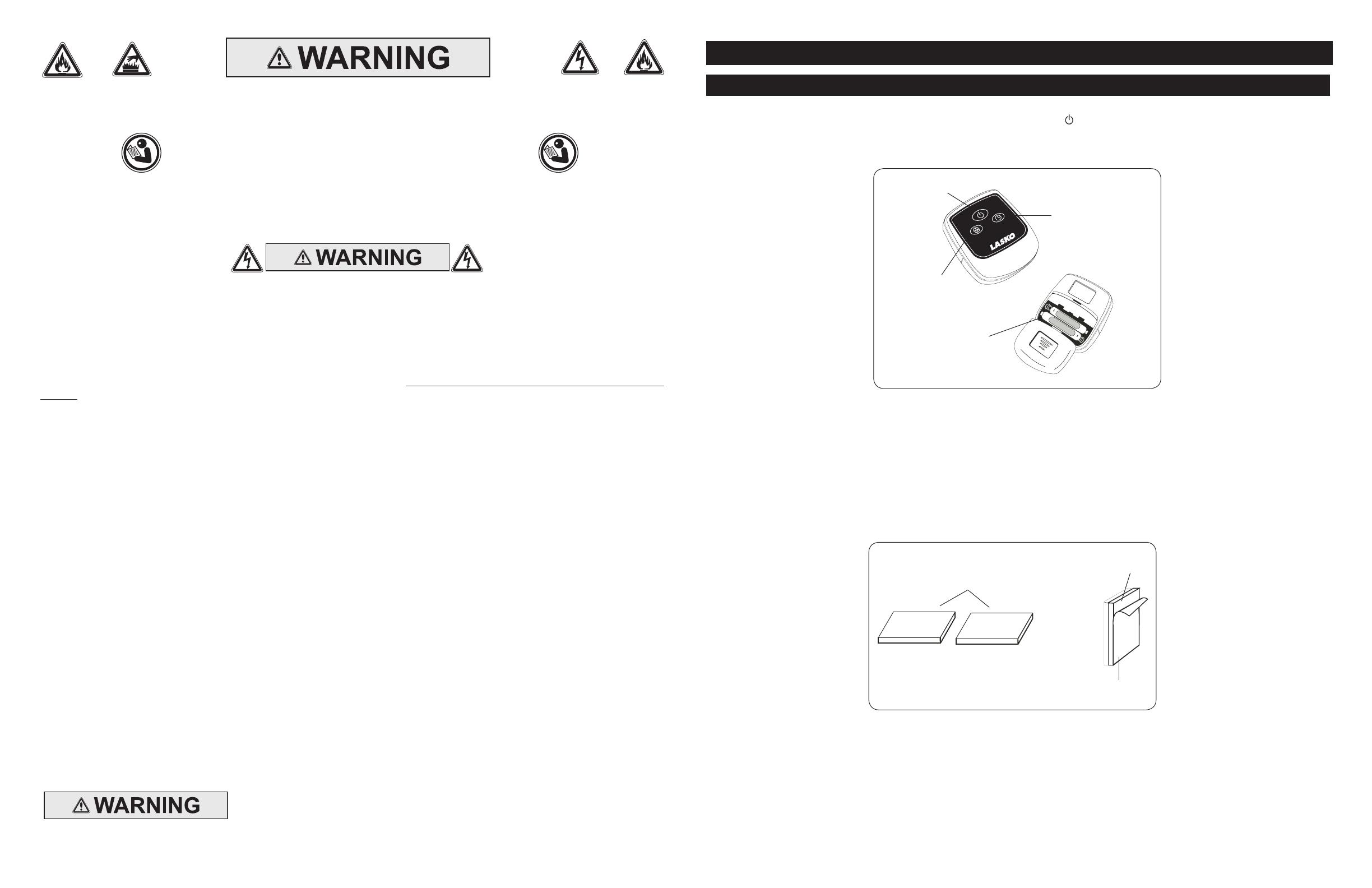
MODELO 1850
Figura 13
Botón
Temporizador
Botón
Alimentación
Botón
Velocidad
Baterías
AAA
Su ventilador de pedestal con control remoto tiene, además, Tiras de Fijacíon. Quite la Película Protectora del dorso de la
pieza cuadrada de Tiras de Fijacíony adhiérala al control remoto. Quite la película protectora del dorso de la otra pieza cuadrada
de Tiras de Fijacíon y adhiérala a su ventilador. Ahora puede guardar su control remoto cuando no lo esté usando. (Figura 14)
Si usted pierde su mando a distancia, por favor Cliente de llamada Serive para ordenar un reaplacement en 1-800 -233-0268,
de lunes a viernes, entre las 8 a.m. y las 5 p.m. (Horario Estándar del Este de los Estados Unidos).
CONTROL REMOTO
Figura 14
Tiras De Fijacíon
Película
Protectora
Adhesivo
1. Instale la baterías (no suministró) como mostrado en la Figura 13. La batería es el tipo “AAA”.
2. El Botón De Encendido del Control Remoto está identicado como ( ).
3. Todas las funciones realizadas con el Control Remoto pueden realizarse de igual forma con los Controles Manuales.
4. No mezcle baterías viejas y nuevas. No mezcle baterías alcalinas, estándar (carbono-cinc) o recargables (níquel-cadmio).
5. No se deshága de baterías en el fuego. baterías pueden estallar o pueden salirse.
MODEL 5132
GENERAL SAFETY INFORMATION
When using electrical appliances, basic precautions should always be followed to re-
duce the risk of re, electrical shock and injury to persons, including the following:
SAVE THESE INSTRUCTIONS
Read all instructions before using this Fan.
1. Make certain the power source conforms to the electrical requirements of the Fan.
2. Make certain that the room is equipped with a working smoke detector.
3. Use this Fan only as described in this manual. Any other use not recommended by the manufacturer may cause re, electrical shock, or
injury to persons.
4. To reduce the risk of personal injury and electric shock, the Fan should not be played with or placed where small children can reach it.
5. Unplug power cord before installing, servicing, or moving the Fan.
DO NOT DEPEND ON THE ON/OFF SWITCH AS THE SOLE MEANS OF DISCONNECTING POWER WHEN SERVICING
OR MOVING THE FAN. ALWAYS UNPLUG THE POWER CORD. ALWAYS TURN OFF AND UNPLUG FAN BEFORE
LEAVING THE AREA. NEVER LEAVE CHILDREN UNATTENDED WHEN THE FAN IS ON OR PLUGGED IN.
6. This Fan must NOT be used in potentially dangerous locations such as ammable, explosive, chemical-laden or wet atmospheres where
gasoline, paint or ammable liquids are used or stored.
7. DO NOT use Fan in or near a window. Rain may create an electrical hazard.
8. Completely assemble Fan, according to instructions, before connecting to power supply.
REDUCE THE RISK OF FIRE OR ELECTRIC SHOCK - DO NOT USE THIS FAN
WITH ANY SOLID STATE SPEED CONTROL DEVICES.
9. Where possible, avoid the use of extension cords because the extension cord may overheat and cause a re. If you must use an extension
cord, minimize the risk of overheating by using the shortest cord possible and ensuring that it is UL listed. NEVER use a single extension
cord to operate more than one Fan. Do not plug Fan into any other cord connected device, such as a power strip, cord reel, surge protec-
tor, multiple outlet adapters or outlet-type air fresheners. The use of such devices may create a re hazard.
10. NEVER operate any Fan with a damaged cord or plug or after the Fan malfunctions, has been dropped or damaged in any manner. There
are no user serviceable parts. Return Fan to an authorized service facility for examination, electrical or mechanical adjustment or repair.
11. NEVER insert or allow ngers or foreign objects to enter any ventilation or exhaust opening as it may cause an electric shock or re, or
damage the Fan. To reduce the risk of re, DO NOT block or tamper with the Fan in any manner while it is in operation.
12. Always place the Fan on a stable, at, level surface when operating, to avoid the chance of the Fan overturning. Locate the Power Cord
so the Fan or other objects are not resting on it. DO NOT run Power Cord under carpeting. DO NOT cover Power Cord with throw rugs,
runners or the like. Arrange Power Cord away from room trafc and where it will not be tripped over.
13. This Fan is not intended for use in wet or damp locations. NEVER locate a Fan where it may fall into a bathtub or other water container.
NEVER use Fan where ammable liquids are used or stored.
14. NEVER use Fan outdoors.
15. Remote controls for other appliances or electronic equipment can sometimes interfere with the operation of this Fan. If this occurs, move
the Fan to another location.
16. Keep Fan remote control unit away from chairs and your bed where it may be sat or laid upon and inadvertently turn on the Fan.
17. This Fan is not suitable for use in agricultural facilities including areas where livestock, poultry or other animals are conned. Please refer
to National Electric Code (NEC) Article 547-7 (2002), or applicable state or local codes or standards relating to electrical requirements for
Agricultural Buildings. THIS FAN DOES NOT MEET THE REQUIRMENTS OF NEC ARTICLE 547-7 (2002).
18. This Fan is not suitable for use in hazardous locations. Please refer to National Electric Code (NEC) Article 500 or applicable state or local
codes or standards relating to electrical requirements for Hazardous locations. THIS FAN DOES NOT MEET THE REQUIRMENTS OF
NEC ARTICLE 500 (2002).
This appliance has a polarized plug (one blade is wider than the other). To reduce the risk of electric shock,
this plug is intended to t in a polarized outlet only one way. Match wide blade of plug to wide slot. Fully
insert. If the plug does not t fully in the outlet, reverse the plug. If it still does not t, contact a qualied
electrician. DO NOT attempt to defeat this safety feature.
This plug is a safety feature, to reduce the risk of re, electric shock and personal injury. DO NOT remove,
replace, repair or tamper with the originally supplied plug. If the Fan does not function properly, it may be due
to the safety device incorporated in this plug. Return to an authorized service center or call 800-233-0268,
Monday - Friday, between 8:00 a.m. and 5:00 p.m. Eastern. If the plug warning label is missing or damaged,
call the toll free number for a replacement label.


