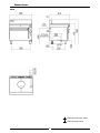
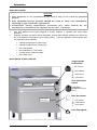
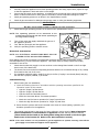
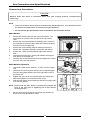
Blue Seal G576 is a Gas Target Top Range Convection Oven that combines a high output, two stage double-ring iron cast burner with a heavy duty motor and 200 mm diameter heavy duty circulation fan. Thanks to that, the appliance has accurate temperature control, is infinitely variable with the heat radiating out from the center of the Target Top, and has a 100watt heavy duty motor. It has a 50 to 320ºC thermostat, an indicator light for power and heating, and automatically cuts off when the oven door is opened.
Blue Seal G576 is a Gas Target Top Range Convection Oven that combines a high output, two stage double-ring iron cast burner with a heavy duty motor and 200 mm diameter heavy duty circulation fan. Thanks to that, the appliance has accurate temperature control, is infinitely variable with the heat radiating out from the center of the Target Top, and has a 100watt heavy duty motor. It has a 50 to 320ºC thermostat, an indicator light for power and heating, and automatically cuts off when the oven door is opened.


-
 1
1
-
 2
2
-
 3
3
-
 4
4
-
 5
5
-
 6
6
-
 7
7
-
 8
8
-
 9
9
-
 10
10
-
 11
11
-
 12
12
-
 13
13
-
 14
14
-
 15
15
-
 16
16
-
 17
17
-
 18
18
-
 19
19
-
 20
20
-
 21
21
-
 22
22
-
 23
23
-
 24
24
-
 25
25
-
 26
26


Blue Seal G576 is a Gas Target Top Range Convection Oven that combines a high output, two stage double-ring iron cast burner with a heavy duty motor and 200 mm diameter heavy duty circulation fan. Thanks to that, the appliance has accurate temperature control, is infinitely variable with the heat radiating out from the center of the Target Top, and has a 100watt heavy duty motor. It has a 50 to 320ºC thermostat, an indicator light for power and heating, and automatically cuts off when the oven door is opened.
Ask a question and I''ll find the answer in the document
Finding information in a document is now easier with AI
Related papers
-
Blue Seal G570 Operating instructions
-
Blue Seal G750-6-N (N_CM603) Owner's manual
-
-
-
-
-
Blue Seal G504D Owner's manual
-
Blue Seal G504D Operating instructions
-
Blue Seal GE56B Operating instructions
-
Blue Seal G506A Specification
Other documents
-
Moffat G576 Operating instructions
-
-
-
Moffat, Inc. VELA90 Datasheet
-
-
 Cafe CXFCHHKPMBZ Installation guide
-
-
-
-
