Craftsman 486.242112 Owner's manual

Category
Garden tools
Type
Owner's manual

This manual is also suitable for

Craftsman 486.242112 is a high-performance 42-inch Lawnsweeper designed to keep your lawn clean and tidy. It boasts a durable construction with a steel housing and hitch tubes, ensuring longevity and reliability. This sweeper's generous 42-inch sweeping width allows you to cover more ground in less time, maximizing efficiency.

Craftsman 486.242112 is a high-performance 42-inch Lawnsweeper designed to keep your lawn clean and tidy. It boasts a durable construction with a steel housing and hitch tubes, ensuring longevity and reliability. This sweeper's generous 42-inch sweeping width allows you to cover more ground in less time, maximizing efficiency.

Owner's Manuat
®
42" HIGH PERFORMANCE
LAWNSWEEPER
Model No, 48&242112
CAUTION:
Before using this product, read this
manuaU and follow aH Safety RuUes
and Operating Instructions.
mMPORTANT o READ THINSFIRST!!!
For Missing Parts or AssembUy Questions
PUease Call 866-576-8388
Mon.-Fri. 7 am - 5 pm CST.
FAX 217-728°2032 or e-maiU [email protected]
Missing parts will be sent UPS in 24 hours directly to your home.
Safety
AssembLy
Operation
Maintenance
Parts
Sears, Roebuck and Co., Hoffman Estates, IL 60179 U.S.A.
wwwasearsacom/craftsman
PRINTED IN U.S.A. FORM NO. 49535 (REV. 1/05)
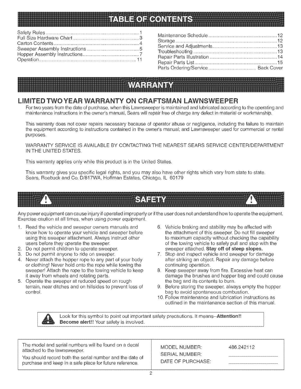
Maintenance Schedule .................................................. 12
Storage .......................................................................... 12
Service and Adjustments ............................................... 13
Troubleshooting ............................................................. 13
Repair Parts Illustration ................................................. 14
Repair Parts List ............................................................ 15
Parts Ordering/Service ................................... Back Cover
LIMITED TWO YEAR WARRANTY ON CRAFTSMAN LAWNSWEEPER
For two years from the date of purchase, when this Lawnsweeper is maintained and lubricated according to the operating and
maintenance instructions in the owner's manual, Sears wil! repair free of charge any defect in material or workmanship.
This warranty does not cover repairs necessary because of operator abuse or negligence, including the failure to maintain
the equipment according to instructions contained in the owner's manual; and Lawnsweeper used for commercia! or rental
purposes.
WARRANTY SERVICE IS AVAILABLE BY CONTACTING THE NEAREST SEARS SERVICE CENTER/DEPARTMENT
IN THE UNITED STATES.
This warranty applies only while this product is in the United States.
This warranty gives you specific legal rights, and you may also have other rights which vary from state to state.
Sears, Roebuck and Co. D/817WA, Hoffman Estates, Chicago, IL 60179
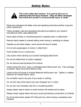
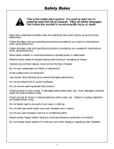
Any power equipment can cause injury ifoperated improperly or ifthe user does not understand how to operate the equipment.
Exercise caution at a!l times, when using power equipment.
1. Read the vehicle and sweeper owners manuals and
know how to operate your vehicle and sweeper before
using this sweeper attachment. Always instruct other
users before they operate the sweeper.
2. Do not permit children to operate sweeper.
3. Do not permit anyone to ride on sweeper.
4. Never attach the hopper rope to any part of your body
or clothing! Never hold onto the rope while towing the
sweeper! Attach the rope to the towing vehicle to keep
it away from wheels and rotating parts.
5. Operate the sweeper at reduced speed on rough
terrain, near ditches and on hillsides to prevent loss of
control.
6. Vehicle braking and stability may be affected with
the attachment of this sweeper. Do not fill sweeper
to maximum capacity without checking the capability
of the towing vehicle to safely pull and stop with the
sweeper attached. Stay off of steep slopes°
7. Stop and inspect vehicle and sweeper for damage
after striking an object. Repair any damage before
continuing operation.
8. Keep sweeper away from fire. Excessive heat can
damage the brushes and hopper bag and could cause
the bag and its contents to burn.
9. Before storing the sweeper, always empty the hopper
bag to avoid spontaneous combustion.
10. Follow maintenance and lubrication instructions as
outlined in the maintenance section of this manual.
Look for this symbol to point out important safety precautions. It means°-Attention!!
Become alert!! Your safety is involved.
The mode! and serial numbers will be found on a decal
attached to the lawnsweeper.
You should record both the serial number and the date of
purchase and keep in a safe place for future reference.
MODEL NUMBER:
SERIAL NUMBER:
DATE OF PURCHASE:
486.242112
.... A .... B .... O
SHOWN FULL SIZE
_,.-m
.... J
I I
\
' ' J 1 I
\
\
M
N
J
I
oi
o
J
NOT SHOWN FULL SIZE
.... R .... S
RER QTY.
A 2
B 2
C 4
D 1
E 8
F 2
G 1
H 1
] 1
DESCRtPTmON
Hex Bolt, 5/16-18 x 3" Lg.
Hex Bolt, 5/16-18 x 2-1/2" Lg.
Hex Bolt, 5/16-18 x 1-3/4" Lg.
Carriage Bolt, 5/16-18 x 1" Lg.
Nylock Nut, 5/16"
Palnut, 3/8"
Flat Washer, 5/16" Standard
Washer, Tooth Lock 5/16"
Spacer Bushing,
RER QT_
J 2
K 1
L 6
M 2
N 2
O 2
P 2
Q 4
R 1
S 1
DESCRtPTmON
Hitch Spacer, 3/4"
Hairpin Cotter, 1/8"
Hairpin Cotter, 3/32"
Clevis Pin, 3/8" x 1/2"
Clevis Pin, 1/4" x 1-1/8"
Clevis Pin, 1/4" x 1-3/4"
Vinyl Cap
Plastic Plug
Grip
Knob, Plastic
CARTONCONTENTS(LoosePartsinCarton)
1, SweeperHousingAssembly
2, BagArmTube(2)
3, HitchTube,L,H,(LeftHand)
4, HitchBracketAssembly
5, HitchBracket,Bent
6, HeightAdjustmentStrap
7, HeightAdjustmentHandle
8, HitchTube,R,H,(RightHand)
9, Rope
10,HopperBag
11,RearHopperTube(2)
12,UpperHopperTube(2)
13,LowerHopperTube(2)
14,HopperBagPivotRod
15,HopperSupportRod(2)
16,BagFrameStrap
CARTONCONTENTS
12
12
3
TOOLS REQUIRED FOR ASSEMBLY
(1) Pliers
(1) Screwdriver
(1) Hammer
(1) Adjustable Wrench
(1) 1/2" Open End or Box End Wrench
(1) 3/8" Open End or Box End Wrench
STEP 1 - REMOVE PARTS FROM CARTON
, To protect painted parts, lay them on cardboard or a
mat,
, Remove the sweeper housing, the loose parts and the
hardware package from the carton, Lay out the parts
and hardware as shown on pages 3 and 4,
STEP 2 - ASSEMBLE HITCH TUBES
The hitch tubes are stamped with a "77L" for the
left tube and a "76R" for the right tube. The sweeper
housing is marked with and "L" on the left with side
and an "R" on the right side. See figure 1.
Hold the left hitch tube against the left side of the
sweeper so that the "77L" on the tube faces away from
the sweeper. Attach the hitch tube using two hex bolts
(C) and nylock nuts (E). Repeat for the right hitch tube,
but with the "76R" facing in toward the right side of the
sweeper. Do not tighten yet. See figure 1.
STEP 3 - REMOVE PLASTmC TiE
. Remove the plastic tie that fastens the height
adjustment tube to the front of the sweeper housing.
See figure 1.
HE× BOLT (C)
l
PLASTIC TIE
/
HInTeRTUBE (LH.)
FIGURE 1
STEP 5 - MEASURE TRACTOR HITCH
. Use the mark beside this paragraph to measure the
height of the tractor hitch. The mark is 10" from the
bottom of the page. If the tractor hitch is less than 10"
above the ground, go to STEP 6a. If the tractor hitch
is 10" or more above the ground, go to STEP 6b.
STEP 6a - ASSEMBLE HITCH BRACKETS
. if the tractor hitch is less than 10" above the ground,
place the bent hitch bracket underneath the hitch
tubes and place the hitch bracket assembly on top of
the hitch tubes, insert two hex bolts (B) through the
brackets, with the rear hex bolt between the cross
bolts in the hitch tubes. Secure the hex bolts (B) with
two nyJock nuts (E). See figure 3. Do not tighten yet.
. AssembJe the two spacers (J) onto the hitch pin and
secure the pin with the hairpin cotter (K). See figure 3.
HEX BOLTS (B)_._
Y'_ _ NYLOBK NUTS (E)
BRACKET
4J.
'_:_" HAIRPmNCOTTER (K}
FIGURE 3
10"
STEP 4 - ASSEMBLE HEIGHT ADJ. STRAP
. Place the spacer bushing (I) into the hole in the
height adjustment strap=Place the strap and bushing
between the hitch tubes, aligning them with the rear
hole. Fasten the hitch tubes together, with the strap
and bushing between them, using two hex bolts (A)
and nyiock nuts (E). Do not tighten yet. See figure 2.
HEX BOLT (A)
NYLOCKNUT(E)
FIGURE 2
STEP 6b - ASSEMBLE HUTCH BRACKETS
. If the tractor hitch is 10" or more above the ground,
place the bent hitch bracket on top of the hitch tubes
and place the hitch bracket assembly underneath
the hitch tubes. Insert two hex bolts (B) through the
brackets, with the rear hex bolt between the cross
bolts in the hitch tubes. Secure the hex bolts (B) with
two nylock nuts (E). See figure 4. Do not tighten yet.
. Assemble the two spacers (J) onto the hitch pin and
secure the pin with the hairpin cotter (K). See figure 4.
NEX BOLTS (B) __._\_
COTTER (K) _ _,//
BENT H|TCH _ '
I
BRACKET
SPACERS (J)/_ ) , '
N'TCNBRACKETi I
NYLOCK NUTS (E)
FIGURE 4
STEP 7 - TIGHTEN BOLTS
, At this time tighten the four bolts in figure 1 that
fasten the hitch tubes to the sweeper housing. Next,
tighten the two bolts in figure 2 that fasten the ends
of the hitch tubes together. Finally, tighten the two
bolts in figure 3 or 4 that fasten the hitch brackets to
the hitch tubes.
STEP 9 - ATTACH KNOB
, Place the tooth=!ock washer (H) between the height
adjustment handle and the height adjustment strap.
insert the carriage bolt (D) through the handle, the
tooth=!ock washer and the strap. Assemble the flat
washer (G) and the plastic knob (S) onto the end of
the bolt and tighten. See figure 6.
STEP 8 - ATTACH HANDLE
, Assemble the height adjustment handle to the height
adjustment tube on the front of the sweeper housing.
Use the curved head bolts, bowed washers, lock
washers and hex nuts which come pre=assembled to
the tube. Position the height adjustment handle side to
side so that the height adjustment strap will align up
against the outside of the handle and then tighten the
nuts. See figure 5.
Assemble the grip (R) onto the end of the height
adjustment handle as shown in figure 5.
HEmGHT
ADJUSTMENT
HANDLE
CURVED
HEAD BOLT /
__ HEmGHT
MENT ADJUSTMENT
STRAP
FIGURE 5
HEIGHT
ADJUSTMENT
HANDLE BOLT (D)
KNOB (S)
FLAT WASHER (G)
FIGURE 6
ASSEMBLY OF HOPPER BAG
STEP 10- ASSEMBLE UPPER TUBES
, Fit the ends of the two upper hopper tubes into the
ends of a rear hopper tube. Align the holes in the ends
of the tubes and insert plastic plugs (Q). See figure 7.
NOTE: Either side of the tubes can face up.
REAR
HOPPER
TUBE
FIGURE 7
STEP 12 - ASSEMBLE TUBES TO BAG
, Unfold the hopper bag, reverse the fold of the mesh
wind screen and then lay the bag out flat with the wind
screen on top and the Craftsman logo facing down.
, insert the ends of the assembled upper hopper tubes
down through the stitched sleeves in the sides of the
hopper bag and then slide the tubes back underneath
the wind screen. See figure 9.
STITCHED SLEEVE
UPPER
HOPPER
TUBE
FIGURE 9
STEP 11 - ASSEMBLE LOWER TUBES
, Fit the ends of the two tower hopper tubes into the
ends of a rear hopper tube. Align the holes in the ends
of the tubes and insert ptastic ptugs (Q). See figure 8.
NOTE: Either side of the rear hopper tube can face up.
LOWER
TUBE
FIGURE 8
Place the assembled !ower hopper tubes into the
bottom of the hopper bag and then slide the tubes to
the back of the bag. See figure 10.
Attach the ends of the lower hopper tubes to the
inside of the upper hopper tubes using two clevis pins
(M) inserted from the inside, and two hair cotter pins
(L). See figure 10.
HAmRCOTTER
PUN(L)
LOWER HOPPER TUBE j
FIGURE 10
HOPPER BAG
BOTTOM
STEP 13 - ATTACH BAG BOTTOM
, insert the bag frame strap into the stitched sleeve at
the front edge of the bag bottom, See figure 11,
Fold the bag flaps around the lower hopper tubes and
attach to the bag bottom using the snaps, See figure
13,
BAG FRAME STRAP
STITCHED
SLEEVE
SNAP
FIGURE 11
FIGURE 13
Assemble the bag frame strap to the holes in the
lower hopper tubes using two clevis pins (N) and hair
cotter pins (L), See figure 12,
BAG FRAME STRAP
STEP 14 - ASSEMBLE SUPPORT RODS
IMPORTANT: Do not over bend the support rods
during the following step, Over bending wil! decrease the
supporting tension of the rods,
Assemble the two hopper support rods as shown in
figure 14, Place the ends of the rods into the holes in
the upper and lower hopper tubes, flexing the rod just
enough to fit into the holes in the tubes,
NOTE: The hopper's mesh wind screen is not shown in
figure 14 in order to better show the hopper support
rods,
CLEVIS PiN [NI
\
FIGURE 12
FIGURE 14
STEP 15 - ASSEMBLE PIVOT ROD
, Slide the hopper bag pivot rod through the upper hole
in the upper hopper tubes and through the stitched
sleeve at the front edge of the mesh wind screen,
assembling a bag arm tube on each side as shown in
figure 15,
UPPER HOLE
STEP 16 -ATTACH ROPE
, Secure the rope to the center of the upper rear hopper
tube as shown in figure 17,
HOPPER BAG
PIVOT ROD FIGURE 17
FIGURE 15
Assemble a vinyl cap (P) onto each bag arm tube as
shown in figure 17,
Assemble two palnuts (F) by lightly tapping them onto
the ends of the pivot rod with a hammer, See figure
16,
HINT: To ease assembly of the palnuts, place the bag
on its side on a solid surface, With the bottom end of
the pivot rod against the surface, tap a palnut onto the
top end of the rod, Repeat for other end of rod,
CAP (P}
PALNUT (F}
STEP 17 - ATTACH HOPPER BAG
To attach the hopper bag to the sweeper, slide the
ends of the bag arm tubes into the ends of the hitch
tubes and secure with two clevis pins (O) and hairpin
cotters (L), See figure 18,
\
FIGURE 18
/
FIGURE 16
ATTACHINGSWEEPERHITCHTO TRACTOR BRUSH HEIGHT ADJUSTED
APPROXUMATELYMInD°WAY
Place the tractor and sweeper on a fiat level sutlace,
Set the sweeper height adjustment handle to about the
middle of its adjustment range,
Attach the sweeper hitch to the tractor hitch, arranging
the 3/4" spacers in one of six possible combinations as
shown in GROUP A and GROUP B diagrams below,
IMPORTANT: To obtain the best performance from your
sweeper, arrange the spacers so that the sweeper bag is
approximately level with the ground and approximately 5"
to 7" off the ground as shown in figure 19,
APPROXUMATELY LEVEL
(5" to 7" FROM SURFACE)
\
FIGURE 19
GROUP "A" - For vehicles with hitches
having 8" to 10" ground clearance.
GROUP "B" o For vehicles with hitches
having 10" to 13" ground clearance.
\
\
\
\
\
HUTCH BRACKET MOUNTED
BELOW HITCH TUBES
BLACK LiNE mSTRACTOR HmTCR
X
\\\
\
HUTCHBRACKET MOUNTED
ABOVE HITCH TUBES
]
\
I
BLACK LiNE mSTRACTOR HmTCR
10
KNOW YOUR SWEEPER
HOPPER BAG
WINDSCREEN
HOPPER
PIVOT ROD ROPE
BAG ARM
TUBE
\ \
L
Hopper Bag
Hopper Rope
Windscreen
Bag Arm Tubes
Pivot Rod
Height Adjustment Handle
Height Adjustment Strap
Knob
Hitch Bracket
Collects grass clippings, leaves and debris,
Permits dumping of hopper bag from driver's seat,
Helps prevent collected material from being blown out of hopper bag,
Connects the hopper bag to the sweeper housing,
Allows hopper bag to tilt forward to dump material,
Adjusts the operating height of the sweeper,
Holds the height adjustment handle in position when locked,
Locks the height adjustment handle to the height adjustment strap,
Connects the sweeper to the towing vehicle, Adjusts for various height tractor hitches,
HOW TO USE YOUR SWEEPER
BRUSH HEIGHT ADJUSTMENT
To adjust your sweeper brushes to the best operating
height, loosen the adjustment knob and push down
on the height adjustment lever to raise the brush, or
push up on the lever to lower the brush, See figure
19, Best adjustment is when the brush setting is 1/2"
down into the grass, Always mow the grass to an
even height before sweeping,
SWEEPING SPEED
Try a starting speed of approximately 3 m,p,h, (third
gear on most tractors), Depending on the conditions,
it may be necessary to adjust the sweeping speed in
order to achieve best results,
DUMPING OF SWEEPER
Your sweeper can be dumped easily without getting
off of the rider or tractor, Simply pu!! the rope forward
to dump the hopper, Always empty hopper after each
use,
CAUTION: Never attach the hopper rope to
any part of your body or clothing! Never hold
onto the rope while towing the sweeper! Attach
the rope to the towing vehicle to keep it away
from wheels and rotating parts,
CAUTION: Keep sweeper away from fire,
Excessive heat can damage the brushes and
hopper bag and could cause the bag and its
contents to burn,
11
CUSTOMER RESPONSIBILmTmES
Read and fo!!ow the maintenance schedule and the
procedures listed in the maintenance section.
MAINTENANCE SCHEDULE __
F,,,,ndatesasyou
complete regular service.
Service
Dates
Checkfor loose fasteners X
Checkfor worn or damaged parts X X
Lubricate brush shaft bearings _ X ....................
Lubricate wheel bearings X
CleanSweeper -- _ X
Clean/Lubricate chain and sprockets X
SCHEDULED MAINTENANCE
, Clean the sweeper after each use.
inspect for worn or damaged parts, such as brushes
and wheels.
Lubricate the brush shaft bearing twice a year with a
few drops of light weight oil. See figure 20.
HEIGHT ADJUSTMENT SLOT
COVER
I<f. _
CLEAN S
AND
S GREASE
OraLBEARINGS HERE
FLAT WASHER
FIGURE 20
HE× BOLT
FIGURE 21
HEX
LOCK
NUT
FLAT i//
WASHER
_HUB CAP/_
Every two years, remove the wheels and clean the
sprockets, chains and gears found inside the wheel
housing. After cleaning, lubricate with an even coat of
light grease. To remove the wheel, pop off the hub cap
using a screwdriver and remove the lock nut and fiat
washer. See figure 21.
CLEANING
Clean sweeper housing with a soft brush or cloth.
Clean debris from hopper bag with a brush or broom.
Remove any material which has wrapped around
brushes or ends of brush shaft.
CAUTION: Before storing the sweeper,
always empty the hopper bag to avoid
spontaneous combustion.
Clean the sweeper and hopper bag thoroughly to help
prevent rust and mildew.
To collapse the hopper bag for storage, remove the two
hopper support rods from the rear of the hopper.
Store in a dry area.
12
BRUSH REPLACEMENT
NOTE: Brush replacement should be done one brush at
a time.
, Remove the hopper bag from the sweeper.
Loosen the hex bolts and lock nuts on two single
brush retainers which clamp one brush to the double
brush retainers. Do Not loosen or remove the bolts
which fasten the double brush retainers to the brush
shaft. See figure 22.
, Slide the brush out of the retainers, noting on which
side of the brush the bristles overlap. See figure 22.
, Install new brush, making sure the bristles overlap on
the same side of the brush as before. See figure 22.
BRUSH ROTATION
BRUSH
SHAFT
OVERLAP
BRmSTLES
SINGLE
BRUSH
RETARNERS
DOUBLE BRUSH BETAmNER
OVERLAP
BBmSTLES
FIGURE 22
BRUSH ROTATION
SPROCKET, CHAIN AND PAWL SERVICE
IMPORTANT: Do not remove both wheels at the same
time to avoid mixing of parts. (The R.R. and LH. ratchet
sprockets are not interchangeable.) Make notes on the
position of washers and snap rings during disassembly.
, Remove the dust cover by removing the two rivets
which fasten it to the wheet housing. (It is not
necessary to remove the dust cover if you are only
cleaning and lubricating the chain and sprockets.)
, Remove the retaining rings and washers which hold
the sprockets onto the shafts.
, Remove the chain and both sprockets, holding them in
position and sliding them off both of the shafts. (Look
for the drive pin, which may fall out of the brush shaft
when the ratchet sprocket is removed.) See figure 23.
, To reassemble, insert the drive pin through the hole
at the end of the brush shaft. Make sure the pin slides
back and forth easily in the shaft.
Lightly grease both shafts and the chain, and fill the
ratchet sprocket with grease. Assemble the chain with
both sprockets back onto the shafts.
, Lightly grease the axle and then reassemble the wheel.
The brushes should rotate onty during forward rotation
of the wheel. If the brushes are driven (rotated) by both
forward and reverse rotation of the wheel, the drive pin
is jamming in the ratchet gear. Disassemble and dean
and lubricate the drive pin and ratchet gear.
FIGURE 23
Wheels skid when sweeping.
Brushes set too low.
, Brushes are jammed
Wheels are jammed.
13
, Adjust height till brushes are 1/2"
down into grass.
, Stop sweeper. Remove obstruction.
Remove one wheel ata time to check
for obstruction or damage. Refer to
Service and Adjustments section.
REPAIR PARTS FOR MODEL 48&242112 -42" HUGH PERFORMANCE LAWNSWEEPER
71
43
70
/
42
54
47
56 14
/55 44
56 3
41 \
/
48
20
52
14
16
/
18
81
4O 28
229 / 30
4 25 B._ / 31
&/26 (_Lr_ /
REPAUR PARTS LiST FOR MODEL 48&242112 - 42" HUGH PERFORMANCE LAWNSWEEPER
REF, PART QTY DESCRIPTION RER
NO. NO. NO.
1 46776
2 46777
3 63467
4 46778
5 24186
6 63468
7 44947
8 44695
9 43086
10 43083
11 62489
12 44232
13 1629-56
14 24198
15 46780
16 43012
17 47189
18 23580
19 23581
20 44008
21 62490
22 23573
23 47046
24 43655
25 1650-21
26 44007
27 43182
28 141
29 1540-31
30 1038
31 2674-32
32 43894
33 43932
34 23400
35 43890
36 43889
37 44137
38 44542
39 43661
40 62791
41 62792
42 48926
1 Hitch Tube, R.H. 43
1 Hitch Tube, LH. 44
1 Housing Assembly 45
1 Skirt, 42" 46
1 Retainer, Skirt 47
1 Height Adjustment Tube Ass'y. 48
2 Bolt, Cvd. Hd. 5/16-18 x 1o5/8" Lg. 49
2 Washer, Bowed 1" x .32" x .06" 50
6 Lock Washer, 5/16" 51
2 Nut, Hex 5/16-18 Thread 52
2 Brush Bushing Ass'y. 53
2 Ball Bearing 54
2 Retainer, Dust Cover 55
1 Brush Shaft 56
4 Brush, 42" 57
8 Bolt, Hex 1/4-20 x 3/4" Lg. 58
12 Nut, Nylock 1/4-20 Thread 59
4 Retainer, Brush (Double) 60
8 Retainer, Brush (Single) 61
2 Washer, Flat 1-1/8" x .78" x .025" 62
2 Sprocket / Gear 63
2 Dust Cover 64
2 Dowel Pin (Drive) 65
2 Ring, Retaining 3/4" 66
4 Ring, Retaining .594" 67
6 Washer, Shim 1-1/8" x .594" x .025" 68
4 Bolt, Hex 5/16-18 x 3/4" Lg. 69
4 Washer, Flat 1-1/2" x .375" x .062" 70
4 Washer, Flat .78" x 1.25" x .06" 71
2 Nut, Nylock 3/8-24 Thread 72
2 Hub Cap 73
2 Ring, Retaining 1/2" 74
2 Bolt, Hex 3/8-24 x 3ol/2" Lg. 75
2 Bushing, Spacer 76
1 Sprocket, Ratchet R.H. (not shown) 77
1 Sprocket, Ratchet LH. 78
4 Washer, 1/2" x 1" x .02" 79
2 Chain, Roller 80
4 Bolt, Hex 1/4-20 x 1" Lg. 81
1 Housing, Wheel Drive Ass'y. LH.
1 Housing, Wheel Drive Ass'y. R.H.
2 Tube, Upper Hopper Frame
PART
NO.
47477
48726
24189
43938
43737
48401
24191
23687
24192
24193
46781
46823
44985
45088
46782
43224
47810
46847
43720
44326
43081
43084
43943
44732
49493
23368
43343
44917
48402
48365
48366
44481
43055
46867
44230
142
49102
43070
C-9M5732
49535
QTY,
2
2
1
2
1
1
1
1
1
1
2
1
2
4
2
2
8
1
1
1
1
4
1
1
1
2
1
2
4
2
2
2
6
2
1
1
4
1
14
1
DESCRIPTION
Tube, Rear Hopper Frame
Tube, Lower Hopper Frame
Strap, Bag Frame
Rod, Hopper Support 34"
Hopper Rope
Hopper Bag
Strap, Height Adjustment
Bracket, Hitch
Bracket, Hitch (Straight)
Handle, Height Adjustment
Tube, Bag Arm
Rod, Hopper Bag Pivot
Wheel & Tire Ass'y. (with bearings)
Wheel Bearing
Bolt, Hex 5/16-18 x 3" Lg.
Bolt, Hex 5/16-18 x 2ol/4" Lg.
Nut, Nylock 5/16-18 Thread
Bushing, Spacer
Knob, Wing 5/16-18 Thread
Bolt, Carriage 5/16-18 x 1" Lg.
Washer, Flat 5/16" Std. Wrt.
Bolt, Hex 5/16-18 x 1-3/4" Lg.
Grip, Height Adjust
Washer, Tooth Lock 5/16"
Pin, Hitch
Tube, Hitch Spacer
Hairpin Cotter, 1/8"
Palnut, 3/8"
Plug, 1/4"
Pin, Clevis 1/4" x 1-1/8"
Pin, Clevis 3/8" x 1/2"
Cap, Viny!
Hairpin Cotter, 3/32" #3
Pin, Clevis 1/4" x 1ol/2" Lg.
Spring, Hitch Pin
Pin, Cotter 1/8" x 3/4" Lg.
Screw, #12 x 1/2" Hex Head
Washer, 3/8" Flat
Rivet, Pop
Owners Manual
15
® Registered Trademark / TM Trademark of Sears, Roebuck and CO.
© Sears Roebuck and Co ® Marca Registrada / TMMarca de Fabrica de Sears Roebuck and Co
  • Page 1 1
  • Page 2 2
  • Page 3 3
  • Page 4 4
  • Page 5 5
  • Page 6 6
  • Page 7 7
  • Page 8 8
  • Page 9 9
  • Page 10 10
  • Page 11 11
  • Page 12 12
  • Page 13 13
  • Page 14 14
  • Page 15 15
  • Page 16 16

Craftsman 486.242112 Owner's manual

Category
Garden tools
Type
Owner's manual
This manual is also suitable for

Craftsman 486.242112 is a high-performance 42-inch Lawnsweeper designed to keep your lawn clean and tidy. It boasts a durable construction with a steel housing and hitch tubes, ensuring longevity and reliability. This sweeper's generous 42-inch sweeping width allows you to cover more ground in less time, maximizing efficiency.

Ask a question and I''ll find the answer in the document

Finding information in a document is now easier with AI