Page is loading ...

C-1
Cisco 7100 Series VPN Router Installation and Configuration Guide
78-6341-03
APPENDIX
C
Cable Specifications
This appendix provides the following cabling and pinout information for the Cisco 7100 series routers:
• Console and Auxiliary Port Cables and Pinouts, page C-1
• Fast Ethernet Port Cables and Pinouts, page C-4
• Cisco 7120-4T1 and Cisco 7140-8T Cables and Pinouts, page C-5
• Cisco 7120-T3, Cisco 7120-E3, Cisco 7140-2T3, and Cisco 7140-2E3 Cables, page C-18
• Cisco 7120-AT3, Cisco 7140-2AT3, Cisco 7120-AE3, Cisco 7140-2AE3, Cisco 7120-SMI3, and
Cisco 7140-2MM3 Cables, page C-19
Note This appendix specifies pinouts only for the pins used. Pins not listed in the tables in this appendix are
not connected.
Console and Auxiliary Port Cables and Pinouts
The router arrives with a console and auxiliary cable kit, which contains the cable and adapters you need
to connect a console (an ASCII terminal or PC running terminal emulation software) or modem to the
router. The console and auxiliary cable kit includes:
• RJ-45-to-RJ-45 rollover cable
• RJ-45-to-DB-9 female data terminal equipment (DTE) adapter labeled TERMINAL
• RJ-45-to-DB-25 female DTE adapter labeled TERMINAL
• RJ-45-to-DB-25 male data communications equipment (DCE) adapter labeled MODEM

C-2
Cisco 7100 Series VPN Router Installation and Configuration Guide
78-6341-03
Appendix C Cable Specifications
Console and Auxiliary Port Cables and Pinouts
Identifying a Rollover Cable
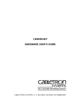
You can identify a rollover cable by comparing the two modular ends of the cable. Holding the cables
side-by-side, with the tab at the back, the wire connected to the pin on the outside of the left plug should
be the same color as the wire connected to the pin on the outside of the right plug. (See Figure C-1.) If
your cable was purchased from Cisco Systems, pin 1 will be white on one connector, and pin 8 will be
white on the other connector (a rollover cable reverses pins 1 and 8, 2 and 7, 3 and 6, and 4 and 5).
Figure C-1 Identifying a Rollover Cable
Console Port Cables and Pinouts
Use the RJ-45-to-RJ-45 rollover cable and RJ-45-to-DB-9 female DTE adapter (labeled TERMINAL) to
connect the console port to a PC running terminal emulation software. Table C-1 lists the signals and
pinouts for the asynchronous serial console port, the RJ-45-to-RJ-45 rollover cable, and the
RJ-45-to-DB-9 female DTE adapter (labeled TERMINAL).
H5663
Table C-1 Console Port Signaling and Cabling Using a DB-9 Adapter
Console Port (DTE) RJ-45-to-RJ-45 Rollover Cable
RJ-45-to-DB-9
Terminal Adapter Console Device
Signal RJ-45 Pin RJ-45 Pin DB-9 Pin Signal
RTS 1
1
1. Pin 1 is connected internally to pin 8.
8 8 CTS
DTR 2 7 6 DSR
TxD 3 6 2 RxD
GND 4 5 5 GND
GND 5 4 5 GND
RxD 6 3 3 TxD
DSR 7 2 4 DTR
CTS 8
1
17 RTS

C-3
Cisco 7100 Series VPN Router Installation and Configuration Guide
78-6341-03
Appendix C Cable Specifications
Console and Auxiliary Port Cables and Pinouts
Use the RJ-45-to-RJ-45 rollover cable and RJ-45-to-DB-25 female DTE adapter (labeled TERMINAL)
to connect the console port to a terminal. Table C-2 lists the signals and pinouts for the asynchronous
serial console port, the RJ-45-to-RJ-45 rollover cable, and the RJ-45-to-DB-25 female DTE adapter
(labeled TERMINAL).
Auxiliary Port Cables and Pinouts
Use the RJ-45-to-RJ-45 rollover cable and RJ-45-to-DB-25 male DCE adapter (labeled MODEM) to
connect the auxiliary port to a modem. Table C-3 lists the signals and pinouts for the asynchronous serial
auxiliary port, the RJ-45-to-RJ-45 rollover cable, and the RJ-45-to-DB-25 male DCE adapter (labeled
MODEM).
Table C-2 Console Port Signaling and Cabling Using a DB-25 Adapter
Console Port
(DTE)
1
1. You can use the same cabling to connect a console to the auxiliary port.
RJ-45-to-RJ-45 Rollover Cable
RJ-45-to-DB-25
Terminal Adapter Console Device
Signal RJ-45 Pin RJ-45 Pin DB-25 Pin Signal
RTS 1
2
2. Pin 1 is connected internally to pin 8.
8 5 CTS
DTR 2 7 6 DSR
TxD 3 6 3 RxD
GND 4 5 7 GND
GND 5 4 7 GND
RxD 6 3 2 TxD
DSR 7 2 20 DTR
CTS 8
1
14RTS
Table C-3 Auxiliary Port Signaling and Cabling Using a DB-25 Adapter
AUX Port (DTE)
RJ-45-to-RJ-45
Rollover Cable
RJ-45-to-DB-25
Modem Adapter Modem (DCE)
Signal RJ-45 Pin RJ-45 Pin DB-25 Pin Signal
RTS 1 8 4 RTS
DTR 2 7 20 DTR
TxD 3 6 3 TxD
GND 4 5 7 GND
GND 5 4 7 GND
RxD 6 3 2 RxD
DSR 7 2 8 DCD
CTS 8 1 5 CTS

C-4
Cisco 7100 Series VPN Router Installation and Configuration Guide
78-6341-03
Appendix C Cable Specifications
Fast Ethernet Port Cables and Pinouts
Fast Ethernet Port Cables and Pinouts
The 10BaseT/100BaseTX Fast Ethernet ports support IEEE 802.3 and IEEE 802.3u specifications for
10-Mbps and 100-Mbps transmission over unshielded twisted-pair (UTP) cables. Each Fast Ethernet
port on the router has an RJ-45 connector to attach to Category 3 or Category 5 UTP cables.
Cisco Systems does not supply Category 3 or Category 5 UTP RJ-45 cables; these cables are available
commercially.
Use a Category 3 UTP crossover cable when connecting 10BaseT port to a hub or use a Category 3 UTP
straight-through cable when connecting to an end station.
Use a Category 5 UTP crossover cable when connecting 100BaseTX to a hub or use a Category 5 UTP
straight-through cable when connecting to an end station.
To determine the type of RJ-45 cable, examine the sequence of colored wires as follows:
• Straight-through—Colored wires are in the same sequence at both ends of the cable.
• Crossover—The first (far left) colored wire at one end of the cable is the third colored wire at the
other end of the cable, and the second colored wire at one end of the cable is the sixth colored wire
at the other end of the cable.
Table C-4 lists the 10BaseT pinouts and Table C-5 lists the 100BaseTX pinouts for the two Fast Ethernet
ports.
Table C-4 10BaseT RJ-45 Connector Pinouts
RJ-45 Pin Description
1 Tx+
2 Tx–
3 Rx+
6 Rx–
Table C-5 100BaseTX RJ-45 Connector Pinouts
RJ-45 Pin Description
1 Tx+
2 Tx–
3 Rx+
6 Rx–

C-5
Cisco 7100 Series VPN Router Installation and Configuration Guide
78-6341-03
Appendix C Cable Specifications
Cisco 7120-4T1 and Cisco 7140-8T Cables and Pinouts
Figure C-2 shows the RJ-45 cable connectors.
Figure C-2 RJ-45 Plug and Receptacle
Cisco 7120-4T1 and Cisco 7140-8T Cables and Pinouts
The four T1 ports on the Cisco 7120-4T1 and the eight T1 ports on the Cisco 7140-8T and adapter cables
allow a high density of interface ports, regardless of the size of the connectors typically used with each
electrical interface type. All ports use an identical 60-pin D-shell receptacle that supports all interface
types:
• EIA/TIA-232
• V.35
• EIA/TIA-449
• X.21
• EIA-530
Each port requires a serial adapter cable, which provides the interface between the high-density serial
port and the standard connectors that are commonly used for each electrical interface type.
Note The adapter cable determines the electrical interface type and mode of the port (DTE or DCE) to which
it is connected.
The network end of the cable is an industry-standard connector for the type of electrical interface that
the cable supports. For most interface types, the adapter cable for DTE mode uses a plug at the network
end, and the cable for DCE mode uses a receptacle at the network end. Exceptions are V.35 adapter
cables, which are available with either a V.35 plug or a receptacle for either mode, and the EIA-530
adapter cable, which is available only in DTE mode with a DB-25 plug at the network end. The mode is
labeled on the molded plastic connector shell at the ends of all cables except V.35 (which uses the
standard Winchester block-type connector instead of a molded plastic D shell).
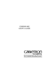
Caution Serial interface cables must be attached correctly, or damage to the cable plug will result. Attempting to
force a cable plug on the 60-pin receptacle can damage the plug. (See Figure C-3.)
H2936
8 7 6 5 4 3 2 1
RJ-45 connector

C-6
Cisco 7100 Series VPN Router Installation and Configuration Guide
78-6341-03
Appendix C Cable Specifications
Cisco 7120-4T1 and Cisco 7140-8T Cables and Pinouts
Figure C-3 Correct Serial Cable Orientation
Table C-6 lists the available interface cable options (and product numbers) for the mode and
network-end connectors.
22138
Router port
Router port
Interface cable
Interface cable
Correct
Incorrect, cable upside down
Table C-6 Serial Cable Product Numbers
Interface Type Description Product Number
EIA/TIA-232 DTE mode with a DB-25 plug CAB-232MT=
DCE mode with a DB-25 receptacle CAB-232FC=
EIA/TIA-449 DTE mode with a 37-pin D-shell plug CAB-449MT=
DCE mode with a 37-pin D-shell receptacle CAB-449C=
V.35 DTE mode or DCE mode with a 34-pin
Winchester-type V.35 plug
CAB-V35MT= or
CAB-V35MC=
DTE mode or DCE mode with a 34-pin
Winchester-type V.35 receptacle
CAB-V35FT= or
CAB-V35FC=
Male DB-60 plug on the router end and a male
DB-34 shielded plug on the network end
CAB-V35MTS=
X.21 DTE mode with a DB-15 plug CAB-X21MT=
DCE mode with a DB-25 receptacle CAB-X21FC=
EIA-530 DTE mode with a DB-25 plug CAB-530MT=

C-7
Cisco 7100 Series VPN Router Installation and Configuration Guide
78-6341-03
Appendix C Cable Specifications
Cisco 7120-4T1 and Cisco 7140-8T Cables and Pinouts
Figure C-4 shows the supported serial cables.
Figure C-4 T1 Serial Cables
Metric (M3) thumbscrews are included with each cable to allow connections to devices that use metric
hardware. Because the T1 ports use a special, high-density port that requires special adapter cables for
each electrical interface type, we recommend that you obtain serial interface cables from the factory.
Serial signals can travel a limited distance at any given bit rate; generally, the slower the baud rate, the
greater the distance. All serial signals are subject to distance limits beyond which a signal degrades
significantly or is completely lost.
Table C-7 lists the recommended (standard) maximum speeds and distances for each serial interface
type. The recommended maximum rate for V.35 is 2.048 Mbps.
Router connections
EIA/TIA-449 V.35 X.21
Network connections at the modem or CSU/DSU
23975
EIA/TIA-232 EIA-530
Table C-7 Recommended (Standard) Maximum Speeds and Distances for Serial Interfaces
EIA/TIA-232 Distances EIA/TIA-449, X.21, V.35, EIA-530 Distances
Rate (bps) Feet Meters Feet Meters
2400 200 60 4,100 1,250
4800 100 30 2,050 625
9600 50 15 1,025 312
19200 25 7.6 513 156
38400 12 3.7 256 78

C-8
Cisco 7100 Series VPN Router Installation and Configuration Guide
78-6341-03
Appendix C Cable Specifications
Cisco 7120-4T1 and Cisco 7140-8T Cables and Pinouts
Balanced drivers allow EIA/TIA-449 signals to travel greater distances than EIA/TIA-232 signals. The
recommended distance limits for EIA/TIA-449 shown in Table C-7 are also valid for V.35, X.21, and
EIA-530. EIA/TIA-449 and EIA-530 support 2.048-Mbps rates, and V.35 supports 2.048-Mbps rates
without any problems; we do not recommend exceeding published specifications for transmission speed
versus distance. Do so at your own risk.
EIA/TIA-232 Connections
The router end of all EIA/TIA-232 adapter cables is a high-density 60-pin plug. The network end of the
adapter cable is a standard 25-pin D-shell connector (known as a DB-25) that is commonly used for
EIA/TIA-232 connections. Figure C-5 shows the connectors at the network end of the adapter cable.
Do not use the Cisco Systems-provided EIA/TIA-232 adapter cable product number CAB-232MT= to
connect a T1 interface that is configured for DTE mode directly to an NEC - NEXTSTAR 1E model
C4969 MD/SAC unit interface that is configured for DCE mode. Doing so will keep transmit and receive
data signals from being properly exchanged between the two interfaces.
Instead, you must connect an additional, intermediate adapter cable—with standard EIA/TIA-232
DB-25 connectors at both ends—from the network end of product number CAB-232MT= to the standard
EIA/TIA-232 DB-25 connector (the DCE interface) on the NEC - NEXTSTAR 1E model C4969
MD/SAC unit. Cisco Systems does not provide this additional cable; however, its signals and pin
assignments are listed in Table C-8.
You can use the Cisco Systems-provided EIA/TIA-232 adapter cable product number CAB-232FC= to
connect a T1 interface that is configured for DCE mode directly to an NEC - NEXTSTAR 1E model
C4969 MD/SAC unit interface that is configured for DTE mode. This cable’s pin assignments are listed
in Table C-9.
Figure C-5 EIA/TIA-232 Adapter Cable Connectors
56000 8.6 2.6 102 31
1544000 (T1) – – 50 15
Table C-7 Recommended (Standard) Maximum Speeds and Distances for Serial Interfaces (continued)
EIA/TIA-232 Distances EIA/TIA-449, X.21, V.35, EIA-530 Distances
Table C-8 EIA/TIA-232 Adapter Cable Signals (DTE)
DTE Cable (CAB-232MT=)
Router End, HD
1
60-Position Plug
Network End,
DB-25 Plug
Signal Pin Pin Signal
H1343a
DTE
DCE

C-9
Cisco 7100 Series VPN Router Installation and Configuration Guide
78-6341-03
Appendix C Cable Specifications
Cisco 7120-4T1 and Cisco 7140-8T Cables and Pinouts
Shield ground 46 – 1 Shield ground
TxD/RxD 41 —> 2 TxD
RxD/TxD 36 <— 3 RxD
RTS/CTS 42 —> 4 RTS
CTS/RTS 35 <— 5 CTS
DSR/DTR 34 <— 6 DSR
Circuit ground 45 – 7 Circuit ground
DCD/LL 33 <— 8 DCD
TxC/NIL 37 <— 15 TxC
RxC/TxCE 38 <— 17 RxC
LL/DCD 44 —> 18 LTST
DTR/DSR 43 —> 20 DTR
TxCE/TxC 39 —> 24 TxCE
Mode 0
Ground
Mode_DCE
50
51
52
– – Shorting group
1. HD = high-density.
Table C-9 EIA/TIA-232 Adapter Cable Signals (DCE)
DCE Cable (CAB-232FC=)
Router End, HD
1
60-Position Plug
Network End,
DB-25 Receptacle
Signal Pin Pin Signal
Shield ground 46 – 1 Shield ground
RxD/TxD 36 <— 2 TxD
TxD/RxD 41 —> 3 RxD
CTS/RTS 35 <— 4 RTS
RTS/CTS 42 —> 5 CTS
DTR/DSR 43 —> 6 DSR
Circuit ground 45 – 7 Circuit ground
LL/DCD 44 —> 8 DCD
TxCE/TxC 39 —> 15 TxC
NIL/RxC 40 —> 17 RxC
DCD/LL 33 <— 18 LTST
DSR/DTR 34 <— 20 DTR
Table C-8 EIA/TIA-232 Adapter Cable Signals (DTE) (continued)
DTE Cable (CAB-232MT=)

C-10
Cisco 7100 Series VPN Router Installation and Configuration Guide
78-6341-03
Appendix C Cable Specifications
Cisco 7120-4T1 and Cisco 7140-8T Cables and Pinouts
EIA/TIA-449 Connections
The router end of all EIA/TIA-449 adapter cables is a high-density 60-pin plug. The network end of the
adapter cable provides a standard 37-pin D-shell connector, which is commonly used for EIA/TIA-449
connections. Figure C-6 shows the connectors at the network end of the adapter cable. EIA/TIA-449
cables are available as either DTE (DB-37 plug) or DCE (DB-37 receptacle). See Table C-10 and
Table C-11 for pinouts.
Figure C-6 EIA/TIA-449 Adapter Cable Connectors
RxC/TxCE 38 <— 24 TxCE
Mode 0
Ground
50
51
– – Shorting group
1. HD = high-density.
Table C-9 EIA/TIA-232 Adapter Cable Signals (DCE) (continued)
DCE Cable (CAB-232FC=)
Table C-10 EIA/TIA-449 Adapter Cable Signals (DTE)
DTE Cable (CAB-449MT=)
Router End, HD
1
60-Position Plug
Network End,
DB-37 Plug
Signal Pin Pin Signal
Shield ground 46 – 1 Shield ground
TxD/RxD+ 11 —> 4 SD+
TxD/RxD– 12 —> 22 SD–
TxC/RxC+ 24 <— 5 ST+
TxC/RxC– 23 <— 23 ST–
RxD/TxD+ 28 <— 6 RD+
RxD/TxD– 27 <— 24 RD–
RTS/CTS+ 9 —> 7 RS+
RTS/CTS– 10 —> 25 RS–
RxC/TxCE+ 26 <— 8 RT+
RxC/TxCE– 25 <— 26 RT–
CTS/RTS+ 1 <— 9 CS+
CTS/RTS– 2 <— 27 CS–
H1344a
DTE
DCE

C-11
Cisco 7100 Series VPN Router Installation and Configuration Guide
78-6341-03
Appendix C Cable Specifications
Cisco 7120-4T1 and Cisco 7140-8T Cables and Pinouts
LL/DCD 44 —> 10 LL
Circuit ground 45 – 37 SC
DSR/DTR+ 3 <— 11 ON+
DSR/DTR– 4 <— 29 ON–
DTR/DSR+ 7 —> 12 TR+
DTR/DSR– 8 —> 30 TR–
DCD/DCD+ 5 <— 13 RR+
DCD/DCD– 6 <— 31 RR–
TxCE/TxC+ 13 —> 17 TT+
TxCE/TxC– 14 —> 35 TT–
Circuit ground 15 – 19 SG
Circuit ground 16 – 20 RC
Mode 1
Ground
49
48
– – Shorting group
Ground
Mode_DCE
51
52
– – Shorting group
1. HD = high-density.
Table C-11 EIA/TIA-449 Adapter Cable Signals (DCE)
DCE Cable (CAB-449C=)
Router End, HD
1
60-Position Plug
Network End,
DB-37 Receptacle
Signal Pin Pin Signal
Shield ground 46 – 1 Shield ground
RxD/TxD+ 28 <— 4 SD+
RxD/TxD– 27 <— 22 SD–
TxCE/TxC+ 13 —> 5 ST+
TxCE/TxC– 14 —> 23 ST–
TxD/RxD+ 11 —> 6 RD+
TxD/RxD– 12 —> 24 RD–
CTS/RTS+ 1 <— 7 RS+
CTS/RTS– 2 <— 25 RS–
TxC/RxC+ 24 —> 8 RT+
TxC/RxC– 23 —> 26 RT–
RTS/CTS+ 9 —> 9 CS+
RTS/CTS– 10 —> 27 CS–
Table C-10 EIA/TIA-449 Adapter Cable Signals (DTE) (continued)
DTE Cable (CAB-449MT=)

C-12
Cisco 7100 Series VPN Router Installation and Configuration Guide
78-6341-03
Appendix C Cable Specifications
Cisco 7120-4T1 and Cisco 7140-8T Cables and Pinouts
V.35 Connections
The router end of all V.35 adapter cables is a high-density 60-pin plug. The network end of the adapter
cable provides a standard 34-pin Winchester-type connector commonly used for V.35 connections.
Figure C-7 shows the connectors at the network end of the V.35 adapter cable. V.35 cables are available
with a standard V.35 plug for DTE mode (CAB-V35MT=) or a V.35 receptacle for DCE mode
(CAB-V35FC=). See Table C-12 and Table C-13 for pinouts.
Figure C-7 V.35 Adapter Cable Connectors
Also available,but not shown in Figure C-7, are CAB-V35MC=, a V.35 cable with a plug on the network
end for DCE mode, and CAB-V35FT=, a V.35 cable with a receptacle on the network end for DTE mode.
These cables are used for connecting V.35-equipped systems back to back.
NIL/LL 29 —> 10 LL
Circuit ground 30 – 37 SC
DTR/DSR+ 7 —> 11 ON+
DTR/DSR– 8 —> 29 ON–
DSR/DTR+ 3 <— 12 TR+
DSR/DTR– 4 <— 30 TR–
DCD/DCD+ 5 —> 13 RR+
DCD/DCD– 6 —> 31 RR–
RxC/TxCE+ 26 <— 17 TT+
RxC/TxCE– 25 <— 35 TT–
Circuit ground 15 – 19 SG
Circuit ground 16 – 20 RC
Mode 1
Ground
49
48
– – Shorting group
1. HD = high-density.
Table C-11 EIA/TIA-449 Adapter Cable Signals (DCE) (continued)
DCE Cable (CAB-449C=)
H1616a
DTE
DCE

C-13
Cisco 7100 Series VPN Router Installation and Configuration Guide
78-6341-03
Appendix C Cable Specifications
Cisco 7120-4T1 and Cisco 7140-8T Cables and Pinouts
Table C-12 V.35 Adapter Cable Signals (DTE)
DTE Cable (CAB-V35FT= or CAB-V35MT=)
Router End, HD
1
60-Position Plug
1. HD = high-density.
Network End, 34-Position Plug
Signal Pin Pin Signal
Shield ground 46 – A Frame ground
Circuit ground 45 – B Circuit ground
RTS/CTS 42 —> C RTS
CTS/RTS 35 <— D CTS
DSR/DTR 34 <— E DSR
DCD/LL 33 <— F RLSD
DTR/DSR 43 —> H DTR
LL/DCD 44 —> K LT
TxD/RxD+ 18 —> P SD+
TxD/RxD– 17 —> S SD–
RxD/TxD+ 28 <— R RD+
RxD/TxD– 27 <— T RD–
TxCE/TxC+ 20 —> U SCTE+
TxCE/TxC– 19 —> W SCTE–
RxC/TxCE+ 26 <— V SCR+
RxC/TxCE– 25 <— X SCR–
TxC/RxC+ 24 <— Y SCT+
TxC/RxC– 23 <— AA SCT–
Mode 1
Ground
49
48
– – Shorting group
Mode 0
Ground
Mode_DCE
50
51
52
– – Shorting group
TxC/NIL
RxC/TxCE
RxC/TxD
Ground
53
54
55
56
– – Shorting group
Table C-13 V.35 Adapter Cable Signals (DCE)
DCE Cable (CAB-V35FC= or CAB-V35MC=)
Router End, HD
1
60-Position Plug
Network End, 34-Position
Receptacle
Signal Pin Pin Signal

C-14
Cisco 7100 Series VPN Router Installation and Configuration Guide
78-6341-03
Appendix C Cable Specifications
Cisco 7120-4T1 and Cisco 7140-8T Cables and Pinouts
Shield ground 46 – A Frame ground
Circuit ground 45 – B Circuit ground
CTS/RTS 35 <— C RTS
RTS/CTS 42 —> D CTS
DTR/DSR 43 —> E DSR
LL/DCD 44 —> F RLSD
DSR/DTR 34 <— H DTR
DCD/LL 33 <— K LT
RxD/TxD+ 28 <— P SD+
RxD/TxD– 27 <— S SD–
TxD/RxD+ 18 —> R RD+
TxD/RxD– 17 —> T RD–
RxC/TxCE+ 26 <— U SCTE+
RxC/TxCE– 25 <— W SCTE–
NIL/RxC+ 22 —> V SCR+
NIL/RxC– 21 —> X SCR–
TxCE/TxC+ 20 —> Y SCT+
TxCE/TxC– 19 —> AA SCT–
Mode 1
Ground
49
48
– – Shorting group
Mode 0
Ground
50
51
– – Shorting group
TxC/NIL
RxC/TxCE
RxC/TxD
Ground
53
54
55
56
– – Shorting group
1. HD = high-density.
Table C-13 V.35 Adapter Cable Signals (DCE) (continued)
DCE Cable (CAB-V35FC= or CAB-V35MC=)

C-15
Cisco 7100 Series VPN Router Installation and Configuration Guide
78-6341-03
Appendix C Cable Specifications
Cisco 7120-4T1 and Cisco 7140-8T Cables and Pinouts
X.21 Connections
The router end of all X.21 adapter cables is a high-density 60-pin plug. The network end of the adapter
cable is a standard DB-15 connector. Figure C-8 shows the connectors at the network end of the X.21
adapter cable. X.21 cables are available as either DTE (DB-15 plug) or DCE (DB-15 receptacle). See
Table C-14 and Table C-15 for pinouts.
Figure C-8 X.21 Adapter Cable Connectors
Table C-14 X.21 Adapter Cable Signals (DTE)
DTE Cable (CAB-X21MT=)
Router End, HD
1
60-Position Plug
1. HD = high-density.
Network End,
DB-15 Plug
Signal Pin Pin Signal
Shield ground 46 – 1 Shield ground
TxD/RxD+ 11 —> 2 Transmit+
TxD/RxD– 12 —> 9 Transmit–
RTS/CTS+ 9 —> 3 Control+
RTS/CTS – 10 —> 10 Control–
RxD/TxD+ 28 <— 4 Receive+
RxD/TxD– 27 <— 11 Receive–
CTS/RTS+ 1 <— 5 Indication+
CTS/RTS – 2 <— 12 Indication–
RxC/TxCE+ 26 <— 6 Timing+
RxC/TxCE– 25 <— 13 Timing–
Circuit ground 15 – 8 Circuit ground
Ground
Mode_2
48
47
– – Shorting group
Ground
Mode_DCE
51
52
– – Shorting group
1
8
15
9
DCE
DTE
H1346a

C-16
Cisco 7100 Series VPN Router Installation and Configuration Guide
78-6341-03
Appendix C Cable Specifications
Cisco 7120-4T1 and Cisco 7140-8T Cables and Pinouts
EIA-530 Connections
The EIA-530 adapter cable is available in DTE mode only. The router end of the EIA-530 adapter cable
is a high-density 60-pin plug. The network end of the adapter cable is a standard DB-25 plug commonly
used for EIA/TIA-232 connections. Figure C-9 shows the DB-25 connector at the network end of the
adapter cable.
Figure C-9 EIA-530 Adapter Cable Connector
Table C-15 X.21 Adapter Cable Signals (DCE)
DCE Cable (CAB-X21FC=)
Router End, HD
1
60-Position Plug
1. HD = high-density.
Network End,
DB-15 Receptacle
Signal Pin Pin Signal
Shield ground 46 – 1 Shield ground
RxD/TxD+ 11 —> 2 Transmit+
RxD/TxD– 12 —> 9 Transmit–
CTS/RTS+ 9 —> 3 Control+
CTS/RTS – 10 —> 10 Control–
TxD/RxD+ 28 <— 4 Receive+
TxD/RxD– 27 <— 11 Receive–
RTS/CTS+ 1 <— 5 Indication+
RTS/CTS– 2 <— 12 Indication–
TxC/RxC+ 26 <— 6 Timing+
TxC/RxC – 25 <— 13 Timing–
Circuit ground 15 – 8 Circuit ground
Ground
Mode_2
48
47
– – Shorting group
Ground
Mode_DCE
51
52
–––
Table C-16 EIA-530 DTE Adapter Cable Signals (CAB-530MT=)
Router End, HD
1
60-Position Plug
Network End,
DB-25 Plug
Signal Pin Pin Signal
Shield ground 46 – 1 Shield ground
DTE
H1615a

C-17
Cisco 7100 Series VPN Router Installation and Configuration Guide
78-6341-03
Appendix C Cable Specifications
Cisco 7120-4T1 and Cisco 7140-8T Cables and Pinouts
TxD/RxD+ 11 —> 2 TxD+
TxD/RxD– 12 —> 14 TxD–
RxD/TxD+ 28 <— 3 RxD+
RxD/TxD– 27 <— 16 RxC–
RTS/CTS+ 9 —> 4 RTS+
RTS/CTS– 10 —> 19 RTS–
CTS/RTS+ 1 <— 5 CTS+
CTS/RTS– 2 <— 13 CTS–
DSR/DTR+ 3 <— 6 DSR+
DSR/DTR– 4 <— 22 DSR–
DCD/DCD+ 5 <— 8 DCD+
DCD/DCD– 6 <— 10 DCD–
TxC/RxC+ 24 <— 15 TxC+
TxC/RxC– 23 <— 12 TxC–
RxC/TxCE+ 26 <— 17 RxC+
RxC/TxCE– 25 <— 9 RxC–
LL/DCD 44 —> 18 LL
Circuit ground 45 – 7 Circuit ground
DTR/DSR+ 7 —> 20 DTR+
DTR/DSR– 8 —> 23 DTR–
TxCE/TxC+ 13 —> 24 TxCE+
TxCE/TxC– 14 —> 11 TxCE–
Mode_1
Ground
Mode_2
49
48
47
– – Shorting group
Ground
Mode_DCE
51
52
– – Shorting group
1. HD = high-density.
Table C-16 EIA-530 DTE Adapter Cable Signals (CAB-530MT=)
Router End, HD
1
60-Position Plug
Network End,
DB-25 Plug

C-18
Cisco 7100 Series VPN Router Installation and Configuration Guide
78-6341-03
Appendix C Cable Specifications
Cisco 7120-T3, Cisco 7120-E3, Cisco 7140-2T3, and Cisco 7140-2E3 Cables
Cisco 7120-T3, Cisco 7120-E3, Cisco 7140-2T3, and
Cisco 7140-2E3 Cables
The T3 or E3 serial interface cable on the Cisco 7120 and Cisco 7140 series, which is a 75-ohm coaxial
cable, is used to connect your router to a T3 or E3 serial network. Serial cables conform to EIA/TIA-612
and EIA/TIA-613 specifications. The serial ports are considered to be DTE devices.
The T3 or E3 serial port has two connectors (receive and transmit) where you connect the Cisco 75-ohm
coaxial cable. The 75-ohm coaxial cable (Cisco product number CAB-ATM-DS3/E3), is available only
from Cisco Systems; it is not available from outside commercial cable vendors.
Figure C-10 shows the Cisco 75-ohm coaxial cable, which is available in 10-foot (3.05-meter) lengths
only. The typical maximum distance between stations for T3 or E3 transmissions is 1300 feet (396
meters).
Note For E3 (75-ohm) connections, you must have ferrite beads on the 75-ohm coaxial cable and
electromagnetic interference (EMI) decoupling clips on the receiver end of the cable (see Figure C-10)
if compliance with Europeancertification standards for emission control is required (EN55022/CISPR22
Class B for radiated emission levels).
Figure C-10 T3 and E3 Serial Port Adapter Cables
The T3 and E3 ports support several types of integrated data service units (DSUs). Table C-17 lists the
features supported.
XMTRRCVR
XMTRRCVR
EN
RCLK
FERF
RL
AIS OOF LL
RCLK
FERF
RL
AIS OOF LL
5
I
To T3 network
equipment
Ferrite bead
22139
75-ohm coaxial cabling
BNC plugBNC plug
EMI decoupler clip
Table C-17 Feature Compatibilities of T3 and E3 Serial Port DSUs
Device Full Rate Scrambling Subrate MDL
1
T3 DSU
DL3100 Yes Yes Yes No
Kentrox Yes Yes
2
Yes
2
No
Larscom Yes Yes Yes No
E3 DSU

C-19
Cisco 7100 Series VPN Router Installation and Configuration Guide
78-6341-03
Appendix C Cable Specifications
Cisco 7120-AT3, Cisco 7140-2AT3, Cisco 7120-AE3, Cisco 7140-2AE3, Cisco 7120-SMI3, and Cisco 7140-2MM3 Cables
Cisco 7120-AT3, Cisco 7140-2AT3, Cisco 7120-AE3,
Cisco 7140-2AE3, Cisco 7120-SMI3, and Cisco 7140-2MM3
Cables
The AT3, AE3, MM3 (OC-3c/STM-1 multimode), and SMI3 (OC-3c/STM-1 single-mode intermediate
reach) interfaces in Cisco 7120 series and Cisco 7140 series routers are full duplex. You must use the
appropriate ATM interface cable to connect the interface with an external ATM network. These
interfaces are considered DTE devices.
Table C-18 summarizes the interface types, connectors, and cables.
Note The ATM port is considered a DTE device.
DL3100E Yes No
3
Yes
3
No
Kentrox Yes Yes
2
Yes
2
No
1. MDL = Maintenance Digital Link.
2. T3 and E3 serial ports support either scrambling or Kentrox subrate, not both at the same time.
3. DL3100E does not support scrambling. However, the E3 serial port can turn on scrambling in DSU mode 0 for connecting
to another E3 serial port. The E3 serial port supports either scrambling (in mode 0) or DL3100E subrate, not both at the
same time.
Table C-17 Feature Compatibilities of T3 and E3 Serial Port DSUs (continued)
Device Full Rate Scrambling Subrate MDL
1
Table C-18 AT3, AE3, MM3, and SMI3 Connector Types and Cables
Interface
Rate
(Mbps)
Connector
Type Cable Type
ITU-T G.957
Standard
Bellcore
GR-253
Standard
Wave-
length
Maximum
Distance
AT3 44.736 BNC Coaxial – – – 450 ft
(137.2 m)
AE3 34.368 BNC Coaxial – – – 1250 ft
(381 m)
MM3 155.52 SC 62.5/125
microns
multimode
Intra-office
STM-1 I-1
Short reach
OC3
1310 nm 1.2 mi
(2 km)
SMI3 155.52 SC 9 microns
single mod
e
Short-haul
STM-1 S-1.1
Intermediat
e reach
OC3
1310 nm 9.3 mi
(15 km)

C-20
Cisco 7100 Series VPN Router Installation and Configuration Guide
78-6341-03
Appendix C Cable Specifications
Cisco 7120-AT3, Cisco 7140-2AT3, Cisco 7120-AE3, Cisco 7140-2AE3, Cisco 7120-SMI3, and Cisco 7140-2MM3 Cables
AT3 and AE3 Cables and Receptacles
The AT3 and AE3 interfaces provide an interface to ATM switching fabrics for the bidirectional
transmission and reception of data at rates of up to 45 Mbps (for T3) and 34 Mbps (for E3).
The AT3 and AE3 interfaces use a 75-ohm coaxial interface cable to connect your router to an ATM T3
or E3 network. The AT3 and AE3 cables (see Figure C-11) conform to EIA/TIA-612 and EIA/TIA-613
specifications. The AT3 and AE3 ports are considered DTE devices.
Figure C-11 AT3 and AE3 Cables
AT3 or AE3 ports consist of two connectors, transmit and receive. The 75-ohm coaxial cable (Cisco
product number CAB-ATM-DS3/E3) is available only from Cisco Systems; it is not available from
outside commercial cable vendors.
The Cisco 75-ohm coaxial cable is available only in 10-foot (3.05-meter) lengths. The typical maximum
distance between stations for T3 and E3 transmissions is 1300 feet (396 meters).
Note To ensure compliance with EMI and European certification standards for emission control
(EN55022/CISPR22 Class B for radiated emission levels), the transmit and receive cables should be tied
together along their entire length, and ferrite beads should be installed on each cable near the transmit
and receive connectors.
75-ohm coaxial cabling
BNC plugBNC plug
22878
5
I
To ATM network
equipment
RX
TX
DS3
RX
EN
CEL CAR ALM
Ferrite bead
/