Page is loading ...

D
Fordern Sie weitere Informationen zur umfangreichen Produktpalette aus dem Hau-
se WAECO an. Bestellen Sie einfach unsere Kataloge kostenlos und unverbindlich
unter der Internetadresse: www.waeco.de
GB
We will be happy to provide you with further information about WAECO products.
Please order our free catalogue with no obligation to buy on our homepage:
www.waeco.com
F
Demandez d’autres informations relatives à la large gamme de produits de la
maison WAECO. Commandez tout simplement notre catalogue gratuitement et
sans engagement à l’adresse internet suivante : www.waeco.com
E
Solicite más información sobre la amplia gama de productos de la empresa WAE-
CO. Solicite simplemente nuestros catálogos de forma gratuita y sin compromiso en
la dirección de Internet: www.waeco.com
I
Per ottenere maggiori informazioni sull’ampia gamma di prodotti WAECO è possibi-
le ordinare una copia gratuita e non vincolante del nostro Catalogo all’indirizzo In-
ternet: www.waeco.com
NL
Maak kennis met het omvangrijke productscala van de firma WAECO. Bestel onze
catalogus gratis en vrijblijvend onder het internetadres: www.waeco.com
DK
Bestil yderligere information om det omfattende produktudvalg fra WAECO.
Bestil vores katalog gratis og uforpligtende på internetadressen: www.waeco.com
S
Inhämta mer information om den omfattande produktpaletten från WAECO:
Beställ våra kataloger gratis och utan förpliktelser under vår Internetadress:
www.waeco.com
N
Be om mer informasjon om det rikholdige produktutvalget fra WAECO. Bestill vår
katalog gratis uforbindtlig på Internettadressen: www.waeco.com
FIN
Pyytäkää lisää tietoja WAECOn kattavista tuotevalikoimista. Tilatkaa tuotekuvastom-
me maksutta ja sitoumuksetta internet-osoitteesta: www.waeco.com
CA-800-Install.book Seite 2 Freitag, 6. Juli 2007 4:16 16

3
CoolAi
r
1
209
401 291
2
1
6
4
5
1
2
3
3
CA-800-Install.book Seite 3 Freitag, 6. Juli 2007 4:16 16

CoolAi
r
4
4
1
5
1
2
3
4
CA-800-Install.book Seite 4 Freitag, 6. Juli 2007 4:16 16
Page is loading ...

CoolAi
r
6
9
1562 3 4 7
8
CA-800-Install.book Seite 6 Freitag, 6. Juli 2007 4:16 16
Page is loading ...
Page is loading ...
Page is loading ...
Page is loading ...
Page is loading ...
Page is loading ...
Page is loading ...
Page is loading ...
Page is loading ...
Page is loading ...
Page is loading ...
Page is loading ...
Page is loading ...
Page is loading ...
Page is loading ...

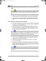
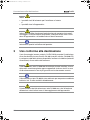
Safety instructions
CoolAi
r
22
Contents
1 Safety instructions. . . . . . . . . . . . . . . . . . . . . . . . . . . . . . . . . . . . . . . . . . . . . . . . . . . .22
1.1 Using the device . . . . . . . . . . . . . . . . . . . . . . . . . . . . . . . . . . . . . . . . . . . . . . . .23
1.1.1 Handling electrical cables. . . . . . . . . . . . . . . . . . . . . . . . . . . . . . . . . . . . . . . . . . . . 23
2 Conventions in this manual . . . . . . . . . . . . . . . . . . . . . . . . . . . . . . . . . . . . . . . . . . . .24
2.1 General information on the installation manual . . . . . . . . . . . . . . . . . . . . . . . . .24
2.2 Target group . . . . . . . . . . . . . . . . . . . . . . . . . . . . . . . . . . . . . . . . . . . . . . . . . . .24
2.3 Symbols and formats. . . . . . . . . . . . . . . . . . . . . . . . . . . . . . . . . . . . . . . . . . . . .24
3 Intended use. . . . . . . . . . . . . . . . . . . . . . . . . . . . . . . . . . . . . . . . . . . . . . . . . . . . . . . . .25
4 Scope of delivery . . . . . . . . . . . . . . . . . . . . . . . . . . . . . . . . . . . . . . . . . . . . . . . . . . . . .26
5 Accessories . . . . . . . . . . . . . . . . . . . . . . . . . . . . . . . . . . . . . . . . . . . . . . . . . . . . . . . . .26
6 Installation . . . . . . . . . . . . . . . . . . . . . . . . . . . . . . . . . . . . . . . . . . . . . . . . . . . . . . . . . .26
6.1 Installation instructions . . . . . . . . . . . . . . . . . . . . . . . . . . . . . . . . . . . . . . . . . . .26
6.2 Installation steps . . . . . . . . . . . . . . . . . . . . . . . . . . . . . . . . . . . . . . . . . . . . . . . .27
6.2.1 Make the roof hatch . . . . . . . . . . . . . . . . . . . . . . . . . . . . . . . . . . . . . . . . . . . . . . . . 28
6.2.2 Prepare the system . . . . . . . . . . . . . . . . . . . . . . . . . . . . . . . . . . . . . . . . . . . . . . . . 28
6.2.3 Secure the balance plate . . . . . . . . . . . . . . . . . . . . . . . . . . . . . . . . . . . . . . . . . . . . 28
6.2.4 Attach the sealing compound to the roof of the driver's cabin . . . . . . . . . . . . . . . . 29
6.2.5 Install the system in the roof hatch. . . . . . . . . . . . . . . . . . . . . . . . . . . . . . . . . . . . . 29
6.2.6 Lay the supply lines . . . . . . . . . . . . . . . . . . . . . . . . . . . . . . . . . . . . . . . . . . . . . . . . 30
6.2.8 Attach the cover frame . . . . . . . . . . . . . . . . . . . . . . . . . . . . . . . . . . . . . . . . . . . . . . 30
6.3 Configuration of system software . . . . . . . . . . . . . . . . . . . . . . . . . . . . . . . . . . .31
6.3.1 Start and end configuration mode . . . . . . . . . . . . . . . . . . . . . . . . . . . . . . . . . . . . . 31
6.3.2 Menu level 1: Set temperature . . . . . . . . . . . . . . . . . . . . . . . . . . . . . . . . . . . . . . . . 32
6.3.3 Menu level 2: Low-voltage cut-off. . . . . . . . . . . . . . . . . . . . . . . . . . . . . . . . . . . . . . 32
6.3.4 Menu level 3: Operating mode . . . . . . . . . . . . . . . . . . . . . . . . . . . . . . . . . . . . . . . . 33
6.3.5 Menu level 4: Default setting . . . . . . . . . . . . . . . . . . . . . . . . . . . . . . . . . . . . . . . . . 34
7 Technical data . . . . . . . . . . . . . . . . . . . . . . . . . . . . . . . . . . . . . . . . . . . . . . . . . . . . . . .34
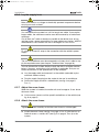
1 Safety instructions
You must read the entire manual thoroughly and carefully.
We can only guarantee reliability of the roof air conditioner if the instruc-
tions are adhered to. The same applies to the prevention of injury and da-
mage to property.
WAECO International assumes no liability for damage resulting from the
following:
Installation errors
Damage to the system resulting from mechanical influences or
overvoltage
Alterations to the roof air conditioner made without the explicit
permission of WAECO International
Use for purposes other than those described in the installation manual
CA-800-Install.book Seite 22 Freitag, 6. Juli 2007 4:16 16

23
Safety instructions
CoolAi
r
1.1 Using the device
Only use the roof air conditioner for the purpose specified by the
manufacturer and do not make any alterations or structural changes to
the device.
Only operate the roof air conditioner if you are certain that the housing
and the cables are not damaged.
The roof air conditioner must be installed safely so that it cannot tip over
or fall down.
Installation, maintenance and repair work may only be carried out by
qualified personnel from a specialist company who are familiar with the
risks involved and the relevant regulations.
Do not use the roof air conditioner near flammable fluids or in closed
rooms.
Do not reach into air grilles or ventilation nozzles or insert any foreign
objects in the system.
Do not undo the upper cover of the roof air conditioner in the event of a
fire. Use approved extinguishing agents instead. Do not use water to
extinguish fires.
Switch off the roof air conditioner before you use automatic washing
equipment (car washes, etc.) to clean the car!
Please ask your vehicle manufacturer if the height entered in your
vehicle documents needs to be altered due to the extra height of the air
conditioning roof unit (extra height 209 mm).
Disconnect all connections to the battery when carrying out work on the
device!
Always manually drain the condensation from the system before
maintenance or tilting the cab (see the section on draining the
condensation in the operating manual for the CoolAir CA-800).
1.1.1 Handling electrical cables
Use cable ducts to lay cables through walls with sharp edges.
Do not lay loose or bent cables next to electrically conductive materials
(metal).
Do not pull on the cables.
Attach and lay the cables in such a manner that they cannot be tripped
over or damaged.
The electrical power supply may only be connected by a qualified
electrician.
Fit a fuse of at least 25 amps to the connection with the vehicle's power
supply.
Never lay power supply lines (battery leads) in the vicinity of signal or
control wires.
CA-800-Install.book Seite 23 Freitag, 6. Juli 2007 4:16 16

Conventions in this manual
CoolAi
r
24
2 Conventions in this manual
2.1 General information on the installation manual
This installation manual contains the essential information and instructions
for installing the roof air conditioner. The information here is intended for
the company installing the roof air conditioner.
The following instructions are intended to help you use the installation
manual properly:
The installation manual is part of the scope of delivery and should be
stored carefully.
The installation manual provides you with important information on the
installation of the device and can also be used as reference material in
the event of repairs.
The manufacturer (WAECO) assumes no liability for non-observance of
these installation instructions. Any claims are excluded in this case.
The operating manual for the CoolAir CA-800 can be found in the scope of
delivery for the roof air conditioner.
2.2 Target group
The installation and configuration information in this manual is intended for
qualified personnel at installation workshops who are familiar with the gui-
delines and safety precautions to be applied during the installation of ve-
hicle accessory parts.
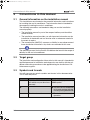
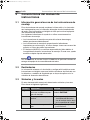
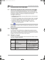
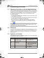
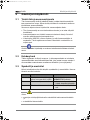
2.3 Symbols and formats
You will come across certain symbols and formats in this documentation.
This is what they mean:
Format Meaning Example
Bold Important information in the
text which may not be misun-
derstood
Set the switch (3) to the COO-
LING symbol.
➤
Instruction text
➤ Lay the roof air conditioner
on a work surface with the
housing facing downwards.
✓ Results of an action ✓ The device is now ready for
operation.
CA-800-Install.book Seite 24 Freitag, 6. Juli 2007 4:16 16

25
Intended use
CoolAi
r
Indication of:
Possible risks of injury to the fitter or user
and
Possible damage to the device
Indicates a potentially dangerous situation which could arise during the in-
stallation or operation of the product and cause damage to the device or
environmental or economic damage.
Special information on handling the product
3 Intended use
The installation kit (item number CA-EK-UNI3) enables you to install a roof
air conditioner CoolAir CA-800 (item number CA-0800-DC) in the already
existing roof hatch (ventilation hatch) of an HGV driver's cabin.
The roof air conditioner CA-800 is not suitable for installation in construc-
tion machines, agricultural machines or similar equipment. It does not work
properly in the event of strong vibrations.
The CA-800 roof air conditioner is only designed for ambient temperatures
of up to 43 °C.
Operating the roof air conditioner CA-800 with voltages other than those
specified can result in damage to the device.
CA-800-Install.book Seite 25 Freitag, 6. Juli 2007 4:16 16

Scope of delivery
CoolAi
r
26
4 Scope of delivery
CA-800 mounting kit for universal installation (existing roof opening)
Item no. CA-EK-UNI3
5 Accessories
6 Installation
The roof air conditioner may only be installed by qualified personnel from a
specialist company. The following information is intended for technicians
who are familiar with the guidelines and safety precautions to be applied.
6.1 Installation instructions
These installation instructions must be read completely prior to the installa-
tion of the roof air conditioner.
The following tips and instructions must be observed while installing the
roof air conditioner:
Make sure that all electrical components are electrically discharged before
carrying out work on them!
Part designation Quantity Item number
Cover frame 1 4443000160
2.5 m insulating tape (profile: 25 x 25 mm) 1 –
2 m insulating tape (profile: 25 x 10 mm) 1 –
Balance plate 1 4442500347
Spacer sleeve L=3 mm 4 4443900170
Rubber buffer M8 4 4445200005
Self-locking nut M8 8 –
Washer M8 8 –
Washer M7 4 –
Cylindrical screws with hexagon socket M6 x 100 4 –
Installation manual 1 4445100302
Part designation Item number
Roof air conditioner CoolAir CA-800 CA-0800-DC
Hood for roof air conditioner CoolAir CA-800 CA-SH1
CA-800-Install.book Seite 26 Freitag, 6. Juli 2007 4:16 16

27
Installation
CoolAi
r
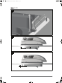
You should always check whether any vehicle components could be
damaged or their function impaired by installing the roof air conditioner
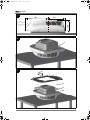
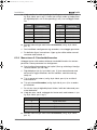
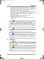
before doing so. Using Fig. 1 on page 3 you can check the dimensions
of the installed system. The broken line here shows the middle of the
roof hatch.
Before installation, find out (by consulting the manufacturer of the
vehicle) whether the construction is designed for the static weight and
the loads of the air conditioner when the vehicle is in motion. The
manufacturer of the roof air conditioner (WAECO) assumes no liability
whatsoever.
The roof inclination of the mounting surface may not be more than 8° to
the front and 0° to the rear.
The supplied assembly parts may not be modified by the customer
when installing them.
Improper installation of the roof air conditioner can result in irreparable da-
mage to the device and put the safety of the user at risk.
If the roof air conditioner is not installed according to the manufacturer's in-
structions, WAECO does not assume any liability. Waeco assumes no lia-
bility for malfunctions or for the safety of the roof air conditioner, especially
for personal injury and/or damage to property.
All connections to the battery of the vehicle should be disconnected before
installing the roof air conditioner.
Non-observance of this regulation can result in danger of electrocution.
After installing the system, the specified parameters of the system soft-
ware must be checked (see chapter "Configuration of system software" on
page 31).
6.2 Installation steps
WAECO International only assumes liability for parts included in the scope
of delivery. The validity of the warranty expires if the device is installed to-
gether with third-party parts.
Check whether the roof of the vehicle is able to support the weight of a
person before climbing onto it. Ask the vehicle manufacturer about the per-
mitted roof loads.
CA-800-Install.book Seite 27 Freitag, 6. Juli 2007 4:16 16

Installation
CoolAi
r
28
6.2.1 Make the roof hatch
➤ Remove all screws and fixtures of the existing sunroof.
➤ Take out the sunroof.
➤ Remove the sealing material from around the opening so that the sur-
face is clean and free of grease.
Dispose of all waste material, glue, silicone and seals separately. Observe
the disposal guidelines.
6.2.2 Prepare the system
While preparing the system on the work surface, make sure it does not fall.
Make sure that the surface is even and clean so that the system is not da-
maged.
➤ Lay the roof air conditioner on a work surface with the housing facing
downwards.
➤ Remove the four M8 bolts, spring washers and washers from the four
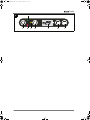
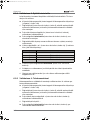
threaded bolts (see fig. 2 on page 3, Pos. 1).
➤ Place the four spacer sleeves L= 3 mm (see fig. 3 on page 3, Pos. 4)
on the four threaded bolts (see fig. 3 on page 3, Pos. 6).
➤ Stick the 2 m long insulation tape (25 x 10 mm, see fig. 3 on page 3,
Pos. 5) into the existing cavity in the system. Apply a plastic, non-har-
dening sealing compound (for example, SikaLastomer-710) to the im-
pact edge and the top edge of the insulation tape.
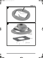
6.2.3 Secure the balance plate
➤ Position the balance plate on the system. To do this, place the four
thread bolts through the four slots in the balance plate.
The balance plate adjusts the roof air conditioner to the specific require-
ments of each vehicle.
➤ Screw one M8 nut each + spring washer + washer (see fig. 3 on
page 3, Pos. 1-3) on to the four thread bolts.
Turn the nuts by hand. The nuts are tightened at a later stage.
CA-800-Install.book Seite 28 Freitag, 6. Juli 2007 4:16 16

29
Installation
CoolAi
r
6.2.4 Attach the sealing compound to the roof of the driver's
cabin
Make sure that the surface for sticking sealing compound between the ba-
lance plate and the roof of the driver's cabin is clean (free from dust, oil,
etc.).
➤ Stick the 2.5 m long insulating tape (25 x 25 mm) along the contour of
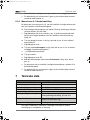
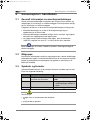
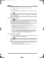
the roof hatch on the roof of the driver's cabin (see fig. 4 on page 4).
➤ Apply a plastic, non-hardening sealing compound (for example, Sika-
Lastomer-710) to the impact edge and the top edge of the insulation
tape.
6.2.5 Install the system in the roof hatch
➤ If necessary, enlarge the two existing ∅ 6.5 mm holes for fastening the
roof hatch (see fig. 4 on page 4, pos. 1, the arrow points to the front of
the vehicle) to a diameter of 8.5 mm.
➤ Position the system in the sunroof opening centrally and in the direc-
tion of travel (see fig. 1 on page 3). The eight fastening bolts for the
balance plate must be put into the drill holes positioned by the manuf-
acturer around the sunroof opening.
Make sure the roof air conditioner is centred perfectly. The seal must be
applied continuously around the roof air conditioner after placing it on the
roof of the vehicle. This is the only way to ensure a tight seal.
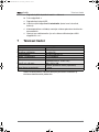
➤ Screw one self-locking M8 nut each + washer (see fig. 5 on page 4,
Pos. 2 and 1) on to the eight fastening bolts. Tighten the nuts with a
torque of 10 Nm to attach the system.
➤ Tighten the four M8 nuts on the thread bolts (see fig. 3 on page 3,
Pos. 6) by hand again.
➤ Screw the four rubber buffers on to the four thread bolts. The space
between the upper edge of the rubber buffer and the roof interior (con-
tact surface of the cover frame) must be calculated using the following
formula: (see fig. 7 on page 5): y = x - 7
The rubber buffers serve as a stop limit for the cover frame and you can
influence the installation position of the cover frame by turning the buffers
up or down.
CA-800-Install.book Seite 29 Freitag, 6. Juli 2007 4:16 16

Installation
CoolAi
r
30
6.2.6 Lay the supply lines
Make sure there is no voltage at electrically operated components before
carrying out work on them!
It is standard that the system has a 3.5 m long 4 mm
2
cable. If you require
longer cables, the cable cross section must be increased by an authorised
workshop:
Cut off the 4 mm
2
cable as closely as possible to the device (max. 0.5 m)
and then make a proper connection to a larger cable cross section. WAECO
recommends a cross section of 6 mm
2
from lengths of 3.5 m to 6 m.
Fit a fuse of at least 25 amps to the connection with the vehicle's power
supply.
The roof air conditioner must be connected to a battery that is able to sup-
ply the required current (see chapter "Technical data" on page 34).
You can connect the system directly to both the HGV's multiplier and the
battery. However, connection to the multiplier is preferable. Ask your ve-
hicle manufacturer for the specifications of the multiplier.
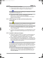
➤ Lay the supply cable and connect it to the vehicle (red cable to plus
and black cable to minus).
➤ Plug the supply line plug into the socket in the roof air conditioner.
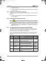
➤ Secure the supply line with a cable binder (see fig. 6 on page 5,
Pos. 1).
6.2.7 Adjust the cover frame
When the system is installed, the outlet unit must be approx. 5 mm above
the cover frame:
➤ Cut the cover frame to suit the specific conbditions of the vehicle (see
fig. 8 on page 5).
6.2.8 Attach the cover frame
Tighten the screws carefully so that the cover frame is not damaged.
➤ Attach the cover frame (see fig. 5 on page 4, Pos. 5) with the four cy-
lindrical screws + washers M7 (see fig. 5 on page 4, Pos. 6) to the
system.
CA-800-Install.book Seite 30 Freitag, 6. Juli 2007 4:16 16

31
Installation
CoolAi
r
6.3 Configuration of system software
Before you first start up the system, adapt the controls according to the in-
stallation conditions. This must be done by the person installing the sys-
tem.
In configuration mode, the following system software parameters must be
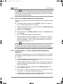
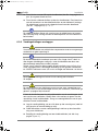
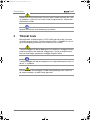
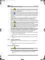
set on the control panel (see fig. 9 on page 6):
The configuration mode can also be called if the undervoltage protection
has switched off the system and there is only residual voltage.
6.3.1 Start and end configuration mode
The adjustable parameters can be altered in edit mode:
➤ With the system switched off, press the ON/OFF button (see fig. 9 on
page 6, Pos. 1) and hold it down for 2-4 seconds.
➤ Additionally press the operating mode button (see fig. 9 on page 6,
Pos. 4) within these 2-4 seconds.
➤ Let go of the ON/OFF button.
➤ Hold the operating mode button pressed until the LED compressor
flashes.
✓ You are now in configuration mode.
✓ The first digit of the display (see fig. 9 on page 6, Pos. 5) shows the
menu level and the second and third show the parameter which can
be set – for example, 1.17 for menu level 1 and a set value of 17 °C.
If you make no entry on the control panel for 60 seconds, the system quits
configuration mode and switches off.
➤ Press the ON/OFF button to quit configuration mode.
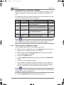
Menu
level
Parameter Meaning
Default
setting
1 Set temperature The system starts with the tempe-
rature defined here.
20 °C
2 Low-voltage
cut-off
The battery monitor switches the
system off at the defined voltage.
ID number
4 = 23.5
Volt
3 Operating mode The system starts with the opera-
ting mode defined here.
0 =
Automatic
mode
4 Default
settings
The parameters 1-3 can be retur-
ned to the default settings.
--
CA-800-Install.book Seite 31 Freitag, 6. Juli 2007 4:16 16

Installation
CoolAi
r
32
6.3.2 Menu level 1: Set temperature
The system always starts with a defined value for the room temperature.
This parameter can be configured between 17 and 30 °C:
➤ Start configuration mode (see chapter "Start and end configuration
mode" on page 31).
✓ The first digit of the display (see fig. 9 on page 6, Pos. 5) shows the
menu level and the second and third show the parameter which can
be set.
➤ Press the operating mode button (see fig. 9 on page 6, Pos. 4) to
change the parameter.
➤ Use the +
or
-
buttons (
see fig. 9 on page 6
, Pos. 6 and 7)
to select the
temperature (in °C) with which the system starts.
✓ The digits in the display flash until the parameter you enter is confir-
med.
➤ Press the operating mode button (see fig. 9 on page 6, Pos. 4) to
confirm your entry.
✓ The set value is saved and is then used when the system is restarted.
✓ You are now in menu level 1 and can use the + and - buttons to switch
between menu levels.
6.3.3 Menu level 2: Low-voltage cut-off
The battery monitor protects the battery from discharging too low.
When the the battery monitor switches the device off, the battery only has
a proportion of its charging capacity. Avoid starting repeatedly or operating
electrical consumers. Ensure that the battery is recharged. As soon as the
required voltage is available, you can restart the system.
If the roof air conditioner only has the supply voltage set here, the system
is switched off.
➤ Start configuration mode (see chapter "Start and end configuration
mode" on page 31).
✓ The first digit of the display (see fig. 9 on page 6, Pos. 5) shows the
menu level and the second and third show the parameter which can
be set.
➤ Press the
+
button (
see fig. 9 on page 6
, 6) once to switch to menu le-
vel
2
.
➤ Press the operating mode button (see fig. 9 on page 6, Pos. 4) to
change the parameter.
✓ The digits in the display flash until the parameter you enter is confir-
med.
➤ Press the +
or
-
buttons
(see fig. 9 on page 6
, Pos. 6 and 7)
to select
the value for the low voltage cut-off. The ID number displayed in the
CA-800-Install.book Seite 32 Freitag, 6. Juli 2007 4:16 16

33
Installation
CoolAi
r
second and third place of the digital display stands for the voltage at
which the system is switched off.
➤ Press the operating mode button (see fig. 9 on page 6, Pos. 4) to
confirm your entry.
✓ The set value is saved and is then used when the system is restarted.
✓ You are now in menu level 2 and can use the + and - buttons to switch
between menu levels.
6.3.4 Menu level 3: Operating mode
The system always starts with a defined operating mode for room tempe-
rature. This parameter can be configured:
➤ Start configuration mode (see chapter "Start and end configuration
mode" on page 31).
✓ The first digit of the display (see fig. 9 on page 6, Pos. 5) shows the
menu level and the second and third show the parameter which can
be set.
➤ Press the
+
button (
see fig. 9 on page 6
, 6) twice to switch to menu le-
vel
3
.
➤ Press the operating mode button (see fig. 9 on page 6, Pos. 4) to
change the parameter.
✓ The digits in the display flash until the parameter you enter is confir-
med.
➤ Use the
buttons
+
or
-
(
see fig. 9 on page 6
, Pos. 6 and 7)
to select the
operating mode with which the system starts.
➤ Press the operating mode button (see fig. 9 on page 6, Pos. 4) to
confirm your entry.
✓ The set value is saved and is then used when the system is restarted.
ID
number
Low-voltage
cut-off
ID
number
Low-voltage
cut-off
1
23,2
6
23,7
2
23,3
7
23,8
3
23,4
8
23,9
4
23,5
9
24,0
5
23,6
10
24,1
ID number Operating mode
0
Automatic mode
1
Operating mode 1
2
Operating mode 2
3
Operating mode 3
CA-800-Install.book Seite 33 Freitag, 6. Juli 2007 4:16 16

Technical data
CoolAi
r
34
✓ You are now in menu level 3 and can use the + and - buttons to switch
between menu levels.
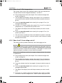
6.3.5 Menu level 4: Default setting
You can return the parameters you set in configuration mode on menu le-
vels 1 to 3 to the default settings:
➤ Start configuration mode (see chapter "Start and end configuration
mode" on page 31).
✓ The first digit of the display (see fig. 9 on page 6, Pos. 5) shows the
menu level and the second and third show the parameter which can
be set.
➤ Press the
+
button (
see fig. 9 on page 6
, 6) three times to switch to
menu level
4
.
✓ The digital display shows --.
➤ Press the operating mode button (see fig. 9 on page 6, Pos. 4) to re-
turn the system to its default settings.
✓ The digits in the display -- flash.
➤ Press the
+
button.
✓ The digital display shows 00.
➤ Press the operating mode button (see fig. 9 on page 6, Pos. 4) to
confirm your entry.
✓ The parameters set in configuration mode are returned to the default
setting.
✓ You are now in menu level 4 and can use the + and - buttons to switch
between menu levels.
7 Technical data
Versions, technical modifications and delivery options reserved.
Roof air conditioner CoolAir CA-800
Item number CA-0800-DC
Cooling capacity: 800 W
Rated input voltage: 24 V DC
Input voltage range: 20 V DC – 30 V DC
Average current consumption: 12 – 22 A
Low-voltage cut-off: Configurable (see chapter "Menu level 2: Low-
voltage cut-off" on page 32)
Dimensions (L x W x H in mm): 690 x 565 x 209
(Height above vehicle roof)
Weight (without balance plate): 20 kg
CA-800-Install.book Seite 34 Freitag, 6. Juli 2007 4:16 16
Page is loading ...
Page is loading ...
Page is loading ...
Page is loading ...
Page is loading ...
Page is loading ...
Page is loading ...
Page is loading ...
Page is loading ...
Page is loading ...
Page is loading ...
Page is loading ...
Page is loading ...
Page is loading ...
Page is loading ...
Page is loading ...
Page is loading ...
Page is loading ...
Page is loading ...
Page is loading ...
Page is loading ...
Page is loading ...
Page is loading ...
Page is loading ...
Page is loading ...
Page is loading ...
Page is loading ...
Page is loading ...
Page is loading ...
Page is loading ...
Page is loading ...
Page is loading ...
Page is loading ...
Page is loading ...
Page is loading ...
Page is loading ...
Page is loading ...
Page is loading ...
Page is loading ...
Page is loading ...
Page is loading ...
Page is loading ...
Page is loading ...
Page is loading ...
Page is loading ...
Page is loading ...
Page is loading ...
Page is loading ...
Page is loading ...
Page is loading ...
Page is loading ...
Page is loading ...
Page is loading ...
Page is loading ...
Page is loading ...
Page is loading ...
Page is loading ...
Page is loading ...
Page is loading ...
Page is loading ...
Page is loading ...
Page is loading ...
Page is loading ...
Page is loading ...
Page is loading ...
Page is loading ...
Page is loading ...
Page is loading ...
Page is loading ...
Page is loading ...
Page is loading ...
Page is loading ...
Page is loading ...
Page is loading ...
Page is loading ...
Page is loading ...
Page is loading ...
Page is loading ...
Page is loading ...
Page is loading ...
Page is loading ...
Page is loading ...
Page is loading ...
Page is loading ...
Page is loading ...
Page is loading ...
Page is loading ...
Page is loading ...
Page is loading ...
Page is loading ...
Page is loading ...
Page is loading ...
Page is loading ...
Page is loading ...
Page is loading ...
Page is loading ...
Page is loading ...
Page is loading ...
Page is loading ...
Page is loading ...
Page is loading ...
Page is loading ...
Page is loading ...
Page is loading ...
Page is loading ...
Page is loading ...
Page is loading ...
Page is loading ...
Page is loading ...

Europe
WAECO Schweiz AG
Riedackerstrasse 7a
CH-8153 Rümlang (Zürich)
℡ +41 44 8187171
+41 44 8187191
Mail: [email protected]
WAECO Danmark A/S
Tværvej 2
DK-6640 Lunderskov
℡ +45 75585966
+45 75586307
Mail: [email protected]
WAECO Ibérica S.A.
Camí del Mig, 106
Poligono Industrial Les Corts
E-08349 Cabrera de Mar
(Barcelona)
℡ +34 93 7502277
+34 93 7500552
Mail: [email protected]
WAECO Distribution SARL
ZAC 2 · Les Portes de L‘Oise
Rue Isaac Newton
F-60230 Chambly (Paris)
℡ +33 1 30282020
+33 1 30282010
Mail: [email protected]
WAECO Finland OY
Mestarintie 4
FIN-01730 Vantaa
℡ +358 20 7413220
+358 9 7593700
Mail: [email protected]
WAECO Italcold SRL
Via dell’Industria 4/0
I-40012 Calderara di Reno (BO)
℡ +39 051 727094
+39 051 727687
Mail: sales@waeco.it
WAECO Norge AS
Leif Weldingsvei 16
N-3208 Sandefjord
℡ +47 33428450
+47 33428459
Mail: firmapost@waeco.no
WAECO Benelux B.V.
Ecustraat 3
NL-4879 NP Etten-Leur
℡ +31 76 5029000
+31 76 5029090
Mail: verkoop@waeco.nl
WAECO Svenska AB
Gustaf Melins gata 7
S-42131 Västra Frölunda
(Göteborg)
℡ +46 31 7341100
+46 31 7341101
Mail: [email protected]
WAECO UK Ltd.
Dorset DT2 8LY · Unit G
Roman Hill Business Park
UK-Broadmayne
℡ +44 1305 854000
+44 1305 854288
Mail: sales@waeco.co.uk
CH
DK
E
F
FIN
I
N
NL
S
UK
Overseas + Middle East
WAECO Pacific Pty. Ltd.
1 John Duncan Court
Varsity Lakes QLD 4227
℡ +61 7 55076000
+61 7 55076001
Mail: [email protected]
WAECO Impex Ltd.
Suites 3210-12 · 32/F · Tower 2
The Gateway · 25 Canton Road
Tsim Sha Tsui · Kowloon
Hong Kong
℡ +852 24632750
+852 24639067
Mail: [email protected]
WAECO Impex Ltd.
Taipei Office
2 FL-3 · No. 56 Tunhua South Rd, Sec 2
Taipei 106, Taiwan
℡ +886 2 27014090
+886 2 27060119
Mail: [email protected]
WAECO Middle East FZCO
R/A 8, SD 6
Jebel Ali, Dubai
℡ +971 4 8833858
+971 4 8833868
Mail: [email protected]
WAECO USA, Inc.
8 Heritage Park Road
Clinton, CT 06413
℡ +1 860 6644911
+1 860 6644912
Mail: customercare@waecousa.com
AUS
HK
ROC
UAE
USA
Headquarters
WAECO International GmbH · Hollefeldstraße 63 · D-48282 Emsdetten
℡ +49 2572 879-195 · +49 2572 879-322 · Mail: [email protected] · Internet: www.waeco.de
D
www.waeco.com
4445100302 07/2007
CA-800-Install.book Seite 144 Freitag, 6. Juli 2007 4:16 16
-
 1
1
-
 2
2
-
 3
3
-
 4
4
-
 5
5
-
 6
6
-
 7
7
-
 8
8
-
 9
9
-
 10
10
-
 11
11
-
 12
12
-
 13
13
-
 14
14
-
 15
15
-
 16
16
-
 17
17
-
 18
18
-
 19
19
-
 20
20
-
 21
21
-
 22
22
-
 23
23
-
 24
24
-
 25
25
-
 26
26
-
 27
27
-
 28
28
-
 29
29
-
 30
30
-
 31
31
-
 32
32
-
 33
33
-
 34
34
-
 35
35
-
 36
36
-
 37
37
-
 38
38
-
 39
39
-
 40
40
-
 41
41
-
 42
42
-
 43
43
-
 44
44
-
 45
45
-
 46
46
-
 47
47
-
 48
48
-
 49
49
-
 50
50
-
 51
51
-
 52
52
-
 53
53
-
 54
54
-
 55
55
-
 56
56
-
 57
57
-
 58
58
-
 59
59
-
 60
60
-
 61
61
-
 62
62
-
 63
63
-
 64
64
-
 65
65
-
 66
66
-
 67
67
-
 68
68
-
 69
69
-
 70
70
-
 71
71
-
 72
72
-
 73
73
-
 74
74
-
 75
75
-
 76
76
-
 77
77
-
 78
78
-
 79
79
-
 80
80
-
 81
81
-
 82
82
-
 83
83
-
 84
84
-
 85
85
-
 86
86
-
 87
87
-
 88
88
-
 89
89
-
 90
90
-
 91
91
-
 92
92
-
 93
93
-
 94
94
-
 95
95
-
 96
96
-
 97
97
-
 98
98
-
 99
99
-
 100
100
-
 101
101
-
 102
102
-
 103
103
-
 104
104
-
 105
105
-
 106
106
-
 107
107
-
 108
108
-
 109
109
-
 110
110
-
 111
111
-
 112
112
-
 113
113
-
 114
114
-
 115
115
-
 116
116
-
 117
117
-
 118
118
-
 119
119
-
 120
120
-
 121
121
-
 122
122
-
 123
123
-
 124
124
-
 125
125
-
 126
126
-
 127
127
-
 128
128
-
 129
129
-
 130
130
-
 131
131
-
 132
132
-
 133
133
-
 134
134
-
 135
135
-
 136
136
-
 137
137
-
 138
138
-
 139
139
-
 140
140
-
 141
141
-
 142
142
-
 143
143
-
 144
144


Waeco CA-800 (Uni3) Installation guide
- Type
- Installation guide
- This manual is also suitable for
Ask a question and I''ll find the answer in the document
Finding information in a document is now easier with AI
in other languages
- italiano: Waeco CA-800 (Uni3) Guida d'installazione
- français: Waeco CA-800 (Uni3) Guide d'installation
- español: Waeco CA-800 (Uni3) Guía de instalación
- Deutsch: Waeco CA-800 (Uni3) Installationsanleitung
- Nederlands: Waeco CA-800 (Uni3) Installatie gids
- dansk: Waeco CA-800 (Uni3) Installationsvejledning
- svenska: Waeco CA-800 (Uni3) Installationsguide
- suomi: Waeco CA-800 (Uni3) Asennusohje
Related papers
-
Waeco CA-800 (Uni1) Operating instructions
-
-
-
-
-
-
-
-
-
Other documents
-
Dometic CA1000 Installation guide
-
-
-
Dometic RCD10.5X Operating instructions
-
-
Dometic CoolAir SP950T Installation guide
-
-
-
Dometic RT780 for Volvo L2H2 Installation guide
-