
SinePower MSI2312T, MSI3512T,
MSI2324T, MSI3524T
NEG -
LCM
CAN1
CAN2
RESET
S1
S2
S3
S4
S5
S6
S7
S8
ENB
ENB
JUMP
1 2
POS +
DE 9 Sinus Wechselrichter
Montage- und Bedienungsanleitung
EN 34 Sine wave inverter
Installation and Operating Manual
FR 57 Onduleur sinusoïdal
Instructions de montage et de service
ES 81 Convertidor de ondas seno
Instrucciones de montaje y de uso
IT 105 Inverter sinusoidale
Istruzioni di montaggio e d’uso
NL 129 Sinus ondulator
Montagehandleiding en gebruiks-
aanwijzing
DA 153 Sinus ensretter
Monterings- og betjeningsvejledning
SV 175 Sinus växelriktare
Monterings- och bruksanvisning
NO 198 Sinus vekselretter
Monterings- og bruksanvisning
FI 221 Sinus -vaihtosuuntaaja
Asennus- ja käyttöohje
PT 243 Conversor sinusoidal
Instruções de montagem e manual de
instruções
RU 266 Синусоидальный инвертор
Инструкция по монтажу и
эксплуатации
PL 292 Przetwornica sinusoidalna
Instrukcja montażu i obsługi
CS 316 Sinusový měnič
Návod k montáži a obsluze

Fordern Sie weitere Informationen zur umfangreichen Produktpalette aus dem Hause
Dometic WAECO an. Bestellen Sie einfach unsere Kataloge kostenlos und
unverbindlich unter der Internetadresse: www.dometic-waeco.de
We will be happy to provide you with further information about Dometic WAECO
products. Please order our free catalogue with no obligation to buy on our homepage:
www.dometic-waeco.com
Demandez d’autres informations relatives à la large gamme de produits de la maison
Dometic WAECO. Commandez tout simplement notre catalogue gratuitement et sans
engagement à l’adresse internet suivante : www.dometic-waeco.com
Solicite más información sobre la amplia gama de productos de la empresa Dometic
WAECO. Solicite simplemente nuestros catálogos de forma gratuita y sin compromiso
en la dirección de Internet: www.dometic-waeco.com
Per ottenere maggiori informazioni sull’ampia gamma di prodotti Dometic WAECO è
possibile ordinare una copia gratuita e non vincolante del nostro Catalogo all’indirizzo
Internet: www.dometic-waeco.com
Maak kennis met het omvangrijke productscala van de firma Dometic WAECO. Bestel
onze catalogus gratis en vrijblijvend onder het internetadres:
www.dometic-waeco.com
Bestil yderligere information om det omfattende produktudvalg fra Dometic WAECO.
Bestil vores katalog gratis og uforpligtende på internetadressen:
www.dometic-waeco.com
Inhämta mer information om den omfattande produktpaletten från Dometic WAECO:
Beställ våra kataloger gratis och utan förpliktelser under vår Internetadress:
www.dometic-waeco.com
Be om mer informasjon om det rikholdige produktutvalget fra Dometic WAECO. Bestill
vår katalog gratis uforbindtlig på Internettadressen: www.dometic-waeco.com
Pyytäkää lisää tietoja Dometic WAECOn kattavista tuotevalikoimista. Tilatkaa
tuotekuvastomme maksutta ja sitoumuksetta internet-osoitteesta:
www.dometic-waeco.com
Peça mais informação sobre a ampla gama de produtos da empresa Dometic
WAECO. Peça simplesmente os nossos catálogos de forma gratuita e sem qualquer
compromisso, disponível no site: www.dometic-waeco.com
Запросите дальнейшую информацию об обширном ассортименте продукции
компании Dometic WAECO. Просто закажите наши каталоги на сайте
www.dometic-waeco.com; эта услуга предоставляется бесплатно и ни к чему не
обязывает.
Proszę się zapoznać z informacjami na temat szerokiej gamy produktów Dometic
WAECO. Proszę zamówić nasz bezpłatny katalog i zapoznać się zniewiążącą ofertą
pod adresem: www.dometic-waeco.com
Žádejte další informace o rozsáhlé nabídce výrobků firmy Dometic WAECO. Stač
í
zdarma a nezávazně objednat naše katalogy na internetové adrese:
www.dometic-waeco.com
DE
EN
FR
ES
IT
NL
DA
SV
NO
FI
PT
RU
PL
CS
Page is loading ...

SinePower
4
3
NEG -
LCM
CAN1
CAN2
RESET
S1
S2
S3
S4
S5
S6
S7
S8
EN
B
ENB
JU
M
P
1 2
POS +
AB
NEG -
LCM
CAN1
CAN2
RESET
S1
S2
S3
S4
S5
S6
S7
S8
ENB
ENB
JUMP
1 2
POS +
1
2
3
4
4
AC OUTPUT
AC
INPUT
AC
OUTPUT
CAN1
BREAKER
NEG -
LCM CAN2
RESET
ON OFF
S1
S2
S3
S4
S5
S6
S7
S8
GND
ENB
ENB
JUMP
1 2
POS +
3
2
9
4
1
5
7
8
10
13
14
1112
6
5
Page is loading ...

SinePower
6
AC
OUTPUT
AC
INPUT
LL
GND
GND
AC INPUT / L
AC INPUT / N
AC OUTPUT / N
AC OUTPUT / L
NN
gr/ge
bk
wt
br
bl
7
ENB
GND
OFF
ON
OFF:INV.
ON:INV.
8
OFF
ON
LOW:INV.
HI:INV.
GND
ENB
(TR ON)
(TR OFF)
TR
9
ENB
BAT+
BAT–
OFF
ON
OFF:INV.
ON:INV.
0
DC POWER
GND
ENB
+
–
OFF
ON
OFF:INV.
ON:INV.
a

SinePower
7
AC OUTPUT
AC
INPUT
AC
OUTPUT
AC OUTPUT
AC
INPUT
AC
OUTPUT
AC OUTPUT
AC
INPUT
AC
OUTPUT
CAN1 CAN2
CAN2
NEG(-) POS(+)
NEG(-) POS(+)
NEG(-) POS(+)
CAN1
rtsw
rtsw rtsw
A
BC
rt
rt
1
1
b

SinePower
8
AC OUTPUT
AC
INPUT
AC
OUTPUT
CAN1
BREAKER
NEG -
LCM CAN2
RESET
ON OFF
S1
S2
S3
S4
S5
S6
S7
S8
GND
ENB
ENB
JUMP
1 2
POS +
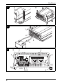
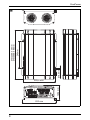
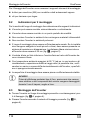
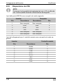
268,6 mm
Ø8,5 mm
283 mm
MSI2300: 436 mm
MSI3500: 496 mm
240 mm
128,4 mm
c
Page is loading ...
Page is loading ...
Page is loading ...
Page is loading ...
Page is loading ...
Page is loading ...
Page is loading ...
Page is loading ...
Page is loading ...
Page is loading ...
Page is loading ...
Page is loading ...
Page is loading ...
Page is loading ...
Page is loading ...
Page is loading ...
Page is loading ...
Page is loading ...
Page is loading ...
Page is loading ...
Page is loading ...
Page is loading ...
Page is loading ...
Page is loading ...
Page is loading ...

EN
SinePower
34
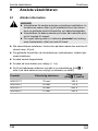
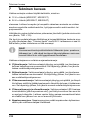
Please read this instruction manual carefully before installation and
first use, and store it in a safe place. If you pass on the product to an-
other person, hand over this instruction manual along with it.
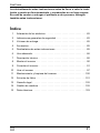
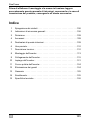
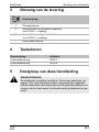
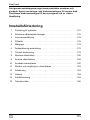
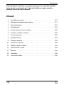
Table of contents
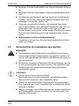
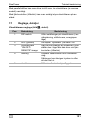
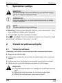
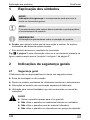
1 Explanation of symbols . . . . . . . . . . . . . . . . . . . . . . . . . . . . . . . . . . 35
2 General safety instructions . . . . . . . . . . . . . . . . . . . . . . . . . . . . . . . 35
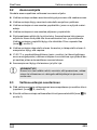
3 Scope of delivery . . . . . . . . . . . . . . . . . . . . . . . . . . . . . . . . . . . . . . . 37
4 Accessories . . . . . . . . . . . . . . . . . . . . . . . . . . . . . . . . . . . . . . . . . . . 38
5 Target group for this manual . . . . . . . . . . . . . . . . . . . . . . . . . . . . . . 38
6 Intended use . . . . . . . . . . . . . . . . . . . . . . . . . . . . . . . . . . . . . . . . . . 38
7 Technical description . . . . . . . . . . . . . . . . . . . . . . . . . . . . . . . . . . . . 39
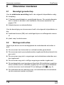
8 Fitting the inverter . . . . . . . . . . . . . . . . . . . . . . . . . . . . . . . . . . . . . . 42
9 Connecting the inverter . . . . . . . . . . . . . . . . . . . . . . . . . . . . . . . . . . 43
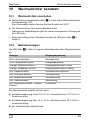
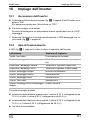
10 Using the inverter. . . . . . . . . . . . . . . . . . . . . . . . . . . . . . . . . . . . . . . 49
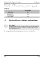
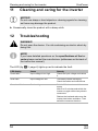
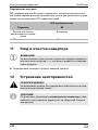
11 Cleaning and caring for the inverter. . . . . . . . . . . . . . . . . . . . . . . . . 52
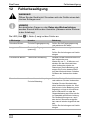
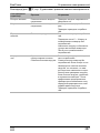
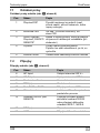
12 Troubleshooting . . . . . . . . . . . . . . . . . . . . . . . . . . . . . . . . . . . . . . . . 52
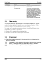
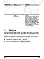
13 Warranty . . . . . . . . . . . . . . . . . . . . . . . . . . . . . . . . . . . . . . . . . . . . . 53
14 Disposal . . . . . . . . . . . . . . . . . . . . . . . . . . . . . . . . . . . . . . . . . . . . . . 53
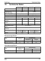
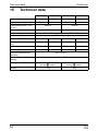
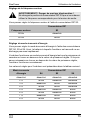
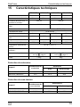
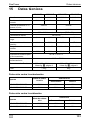
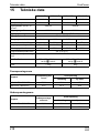
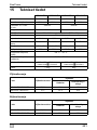
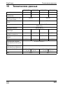
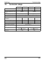
15 Technical data . . . . . . . . . . . . . . . . . . . . . . . . . . . . . . . . . . . . . . . . . 54

EN
SinePower Explanation of symbols
35
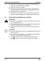
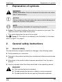
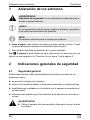
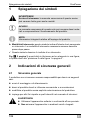
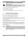
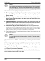
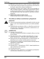
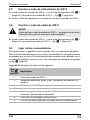
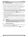
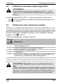
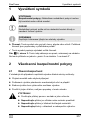
1 Explanation of symbols
!
A
I
➤ Action: This symbol indicates that action is required on your part. The
required action is described step-by-step.
✓ This symbol describes the result of an action.
Fig. 1 5, page 3: This refers to an element in an illustration. In this case,
item 5 in figure 1 on page 3.
2 General safety instructions
2.1 General safety
The manufacturer accepts no liability for damage in the following cases:
Faulty assembly or connection
Damage to the product resulting from mechanical influences and excess
voltage
Alterations to the product without express permission from the manu-
facturer
Use for purposes other than those described in the operating manual
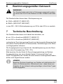
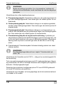
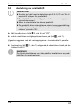
!
WARNING!
Only use the device as intended.
Do not operate the device in a damp or wet environment.
Do not operate the device near any flammable materials.
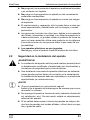
WARNING!
Safety instruction: Failure to observe this instruction can cause
fatal or serious injury.
NOTICE!
Failure to observe this instruction can cause material damage and
impair the function of the product.
NOTE
Supplementary information for operating the product.

EN
General safety instructions SinePower
36
Do not operate the device in areas that are potentially explo-
sive.
Maintenance and repair work may only be carried out by quali-
fied personnel who are familiar with the risks involved and the
relevant regulations.
People (including children) whose physical, sensory or mental
capacities or whose lack of experience or knowledge prevent
them from using this product safely should not use it without the
supervision or instruction of a responsible person.
Electrical devices are not toys
Always keep and use the device out of the reach of children.
2.2 Safety when installing the device
!
WARNING!
Installing the device may only be performed by qualified person-
nel who are familiar with the guidelines and safety precautions
to be applied.
If electrical devices are incorrectly installed on boats, corrosion
damage might occur. The device should be installed by a spe-
cialist (marine) electrician.
A
NOTICE!
Ensure that the device is standing firmly.
The device must be set up and fastened in such a way that it
cannot tip over or fall down.
Do not expose the device to a heat source (such as direct sun-
light or heating). Avoid additional heating of the device in this
way.
If cables have to be fed through metal walls or other walls with
sharp edges, use ducts or tubes to prevent damage.
Do not lay cables which are loose or bent next to electrically
conductive material (metal).
Do not pull on the cables.
Do not lay the 230 V mains cable and the 12/24 V DC cable in
the same duct.
Fasten the cables securely.
Lay the cables so that they cannot be tripped over or damaged.

EN
SinePower Scope of delivery
37
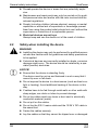
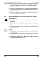
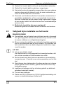
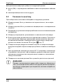
2.3 Operating the device safely
!
WARNING!
Operate the device only if you are certain that the housing and
the cables are undamaged.
Even after the fuse triggers, parts of the inverter remain live.
Always disconnect the power supply when working on the de-
vice.
A
NOTICE!
Make sure the air inlets and outlets of the device are not cov-
ered.
Ensure good ventilation. The inverter produces dissipated heat
which has to be diverted.
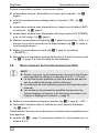
Do not connect the 230 V output of the inverter (fig. 5 7,
page 4) to a different 230 V source.
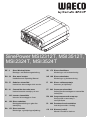
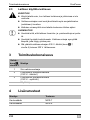
3 Scope of delivery
No. in
fig. 1,
page 3
Designation
1 Sine wave inverter
2 Connection cable with safety coupling
(for 230 Vw output)
3 Connection cable with safety plug
(for 230 Vw supply)
– Operating manual

EN
Accessories SinePower
38
4 Accessories
5 Target group for this manual
!
6 Intended use
!
The wave inverter converts direct current of
12 Vg (MSI2312T, MSI3512T)
24 Vg (MSI 2324T, MSI3524T)
into a 200 – 240 V AC supply of 50 Hz or 60 Hz.
Designation Item no.
Remote control MCR-7
Remote control MCR-9
WARNING!
The electrical installation (chapter “Connecting the inverter” on
page 43) is intended for professionals who are familiar with the
applicable regulations of the country in which the equipment is to
be installed and/or used.
WARNING!
Never use the inverter on vehicles where the positive terminal of
the battery is connected to the chassis.

EN
SinePower Technical description
39
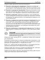
7 Technical description
The inverters can be operated wherever
a 12 Vg connection (MSI2312T, MSI3512T)
a 24 Vg connection (MSI2324T, MSI3524T)
is available. The light-weight and compact construction of this device allows
for easy installation in mobile homes, commercial vehicles or motor and sail-
ing yachts.
The output voltage corresponds to the household voltage from the socket
(pure sine wave, THD < 3%).
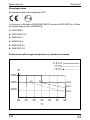
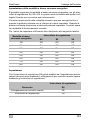
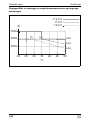
Please observe the values for constant output power and peak output power
as indicated in chapter “Technical data” on page 54 . Never connect devices
that have a higher power requirement.
I
The inverter has various protective mechanisms.
Overvoltage shutdown: The inverter shuts itself off when the voltage ex-
ceeds the cut-off value. It restarts when the voltage returns to the restart
value.
Undervoltage shutdown: The inverter shuts itself off when the voltage
sinks below the cut-off value. It restarts when the voltage rises to the re-
start value.
Excess temperature shutdown: The inverter switches off when the tem-
perature inside the device or the temperature on the cooling element ex-
ceeds a cut-off value. It restarts when the voltage rises to the restart
value.
Overloading and short circuit shutdown: The LED on the inverter indi-
cates an operating fault (constant red light) when an excess load is con-
nected or a short circuit has occurred. The fuse in the device must be
pressed in again by hand after it is triggered by excess current.
Incorrect polarity protection: The incorrect polarity protection prevents
the wrong polarity when connecting the inverter.
NOTE
Note when connecting devices with an electrical drive (such as
power drills and refrigerators), that they often require more power
than is indicated on the type plate.

EN
Technical description SinePower
40
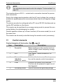
I
The inverters have a 230 Vw socket and a connection terminal for perma-
nent connection.
Due to the voltage synchronisation with the AC input voltage, the inverter is
suitable for operating sensitive consumers which react to an irregular voltage
supply.
The device can also be configured with a PC via an RS 232 interface and us-
ing the DIP switches on the device.
The inverter can be switched to an energy-saving mode to prevent the con-
nected battery from discharging too quickly.
Parallel operation allows up to three inverters (of the same model) to run at
the same time.
The inverter can be easily controlled using the remote control (accessory).
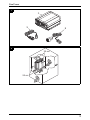
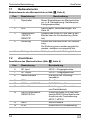
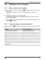
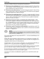
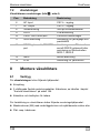
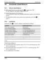
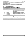
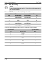
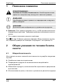
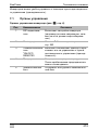
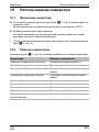
7.1 Control elements
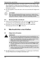
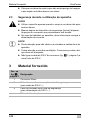
Control elements of the inverter (fig. 5, page 4)
NOTE
The individual values are found in the chapter “Technical data” on
page 54.
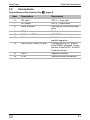
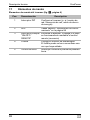
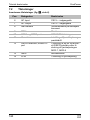
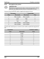
Item Description Description
1 Dip switch Makes settings on the inverter (such as
mains voltage, mains frequency, energy-
saving mode).
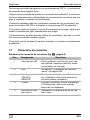
2 LED See chapter “Status indications” on
page 49
3 Main switch
“ON/OFF/
REMOTE” switch:
Switches the device on, off or to opera-
tion via the remote control (accessory)
4 Fuse Protects the inverter from overload.
The fuse can be pressed in again once it
has triggered.
5 Grounding screw Sets or removes the grounding bridge

EN
SinePower Technical description
41
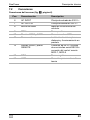
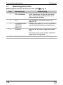
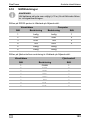
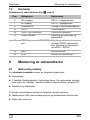
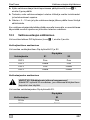
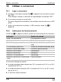
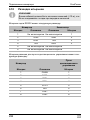
7.2 Connections
Connections of the inverter (fig. 5, page 4)
Item Description Description
6 AC input 230 Vw input jack
7 AC output 230 Vw output jack
8 Earth terminal Earthing on the vehicle body-
work
9 POS+ Positive terminal
10 CAN1 and CAN2 port CAN BUS connections
11 Green terminal Setup of remote switch and
parallel operation
12 RS232 port, REMOTE port Connection of a PC using a
serial RS232 interface or con-
nection of the MCR-7 or MCR-
9 remote control
13 NEG– Negative terminal
14 LCM Remote control connection

EN
Fitting the inverter SinePower
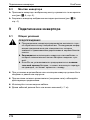
42
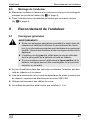
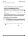
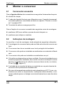
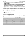
8 Fitting the inverter
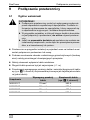
8.1 Tools required
For the electrical connection you will need the following tools:
Crimping tool
3multi-coloured, flexible connection cables. Determine the necessary
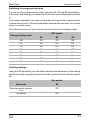
thickness from the table in chapter “Connecting the inverter” on page 43.
Cable lugs and conductor sleeves
For fastening you will require the following tools:
Machine bolts (M4) with washers and self-locking nuts or
self-tapping screws or wood screws.
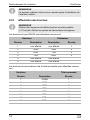
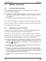
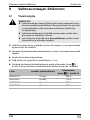
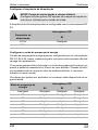
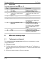
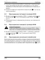
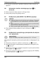
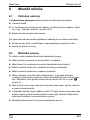
8.2 Mounting instructions
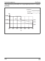
When selecting the installation location, observe the following instructions:
The inverter can be mounted horizontally or vertically.
The inverter must be installed in a place that is protected from moisture.
The inverter may not be installed in the presence of flammable materials.
The inverter may not be installed in a dusty environment.
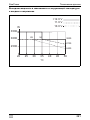
The place of installation must be well ventilated. A ventilation system must
be available for installations in small, enclosed spaces. The minimum
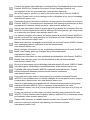
clearance around the inverter must be at least 25 cm (fig. 2, page 3).
The air intake on the underside or the air outlet on the back of the inverter
must remain clear.
For ambient temperatures higher than 50 °C (such as in engine or heating
compartments, or direct sunlight), the heat from the inverter under load
can lead to automatic shutdown.
The device must be installed on a level and sufficiently sturdy surface.

EN
SinePower Connecting the inverter
43
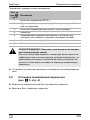
A
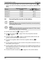
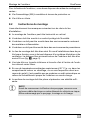
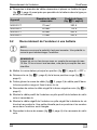
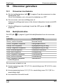
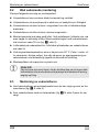
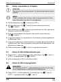
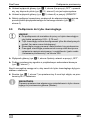
8.3 Mounting the inverter
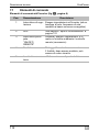
➤ Hold the inverter against the installation location and mark the fastening
points (fig. 3 A, page 4).
➤ Attach the inverter using your chosen fastening method (fig. 3 B,
page 4).
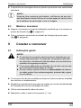
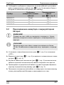
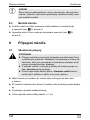
9 Connecting the inverter
9.1 General instructions
!
When installed in vehicles or boats, the inverter must be connected to the
chassis or earth.
When setting up a socket distribution circuit (mains setup), comply with
the applicable regulations.
Only use copper cables.
Keep the cables as short as possible (< 1 m).
NOTICE!
Before drilling any holes, make sure that no electrical cables or
other parts of the vehicle can be damaged by drilling, sawing and
filing.
WARNING!
The inverter may only be connected by a qualified workshop.
The following information is intended for technicians who are
familiar with the guidelines and safety precautions to be ap-
plied.
Never use the inverter on vehicles where the positive terminal
of the battery is connected to the chassis.
If you do not fit a fuse to the positive cable, the cables can
overload, which might result in a fire.

EN
Connecting the inverter SinePower
44
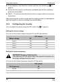
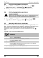
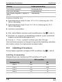
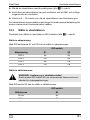
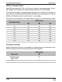
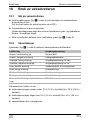
Keep to the specified cable cross section and fit a cable fuse (fig. 4 3,
page 4) as close to the battery as possible on the positive cable (see the
table).
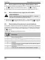
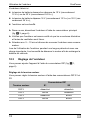
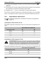
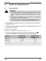
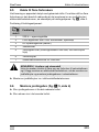
9.2 Connecting the inverter to the battery
A
I
➤ Set the main switch (fig. 5 3, page 4) to “OFF”.
➤ Loosen the screw (fig. 4 1, page 4) from the red positive terminal
(fig. 4 2, page 4).
➤ Push the cable lug (fig. 4 2, page 4) of the positive cable into the red
positive terminal and fasten it with the bolt.
➤ Connect the negative cable to the black negative cable (fig. 4 4,
page 4).
➤ Lay the positive cable from the inverter to the positive terminal of the ve-
hicle battery and connect it.
➤ Lay the negative cable from the inverter to the negative terminal of the ve-
hicle battery and connect it. A small spark can occur if the capacitors are
being charged in the inverter.
➤ Connect the earth terminal (fig. 5 8, page 4) to the vehicle chassis.
Device
Required cable cross
section
Cable fuse
(fig. 4 3, page 4)
MSI2312T 70 mm² 350 A
MSI2324T 50 mm² 175 A
MSI3512T 95 mm² 400 A
MSI3524T 70 mm² 200 A
NOTICE!
Make sure that you do not reverse the polarity. Incorrect polarity
can damage the inverter.
NOTE
Tighten the nuts and bolts to a maximum torque of 15 Nm. Loose
connections may cause overheating.

EN
SinePower Connecting the inverter
45
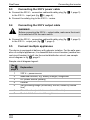
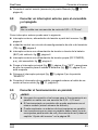
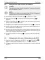
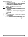
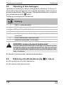
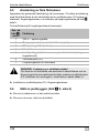
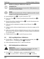
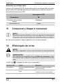
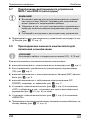
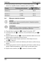
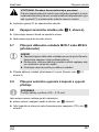
9.3 Connecting the 230 V power cable
➤ Connect the 230 Vw connection cable with safety plug (fig. 1 3, page 3)
to the 230 Vw input jack (fig. 5 6, page 4).
➤ Connect the safety plug to the 230 Vw mains.
9.4 Connecting the 230 V output cable
!
➤ Connect the 230 Vw connection cable with safety plug (fig. 1 2, page 3)
to the 230 Vw output jack (fig. 5 7, page 4).
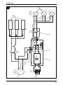
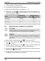
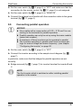
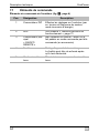
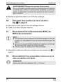
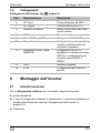
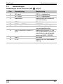
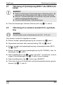
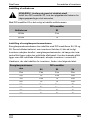
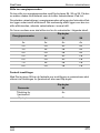
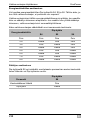
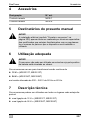
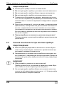
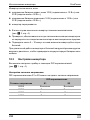
9.5 Connect multiple appliances
The device is equipped at delivery with galvanic isolation. For the safe oper-
ation of multiple appliances, it is essential that a circuit breaker (residual cur-
rent circuit breaker) is built into the socket distribution circuit, see sample
circuit diagram in fig. 6, page 5.
Sample circuit diagram legend:
WARNING!
Before connecting the 230 Vw output cable, make sure the invert-
er is switched off at the main switch.
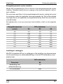
No. in
fig. 6,
page 5
Explanation
1 230 Vw power source
2 additional devices, e.g. battery charger, refrigerator
3 DC power source (battery)
4 Inverter
5 Set grounding bridge (At delivery: not set, shown by dotted
line)
6 Circuit breaker (residual current circuit breaker)
7 Socket distribution circuit for appliances

EN
Connecting the inverter SinePower
46
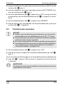
!
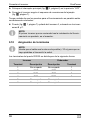
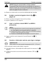
➤ Install a residual current circuit breaker in the socket distribution circuit.
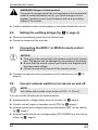
9.6 Setting the earthing bridge (fig. 5 5, page 4)
➤ Remove the earthing screw from the bottom hole.
➤ Screw the screw into the top hole.
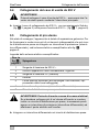
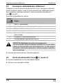
9.7 Connecting the MCR-7 or MCR-9 remote control
(accessory)
A
➤ Connect the remote control (accessory) to the remote port (fig. 5 12,
page 4).
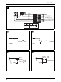
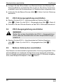
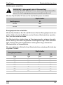
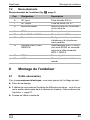
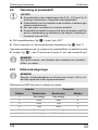
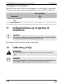
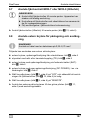
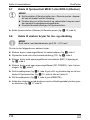
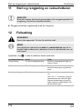
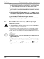
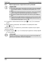
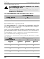
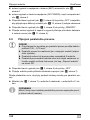
9.8 Connect external switch to turn device on and off
I
You can use the following as an external switch:
external switch, voltage supply from the inverter: fig. 8, page 6
Control unit with relay or transistor circuit (TR): fig. 9, page 6
external switch with voltage supply from the battery (BAT) of the vehicle:
fig. 0, page 6
external switch with its own voltage supply (DC POWER) e.g. from the ig-
nition: fig. a, page 6
WARNING! Danger of electrocution!
If you wish to connect more than one appliance to the inverter and
install a socket distribution circuit, you must arrange a circuit
breaker (residual current circuit breaker) and set a grounding
bridge in the inverter.
NOTICE!
Only plug in the connection to the remote control in the remote
port. The device can be damaged by connecting it incorrectly.
Ensure that the remote control and inverter are supplied with
the same input voltage.
Follow the instruction manual of the remote control.
NOTE
Use cables with a cable cross section of 0.25 – 0.75 mm².

EN
SinePower Connecting the inverter
47
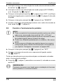
➤ Set the main switch (fig. 5 3, page 4) to “OFF” and make sure that the
connection for the remote control (fig. 5 12, page 4) is not assigned.
➤ Set the main switch (fig. 5 3, page 4) to “REMOTE”.
➤ Connect the external on/off switch with the connection cable to the green
terminal (fig. 5 11, page 4).
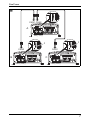
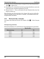
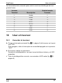
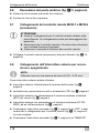
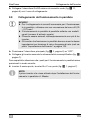
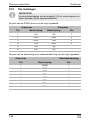
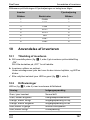
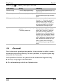
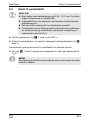
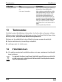
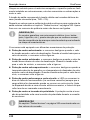
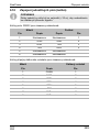
9.9 Connecting parallel operation
A
➤ Set the main switch (fig. 5 3, page 4) to “OFF”.
➤ Connect the inverter according to the sample circuit diagram (fig. b,
page 7).
In particular, make sure that the bridges for parallel operation are set
correctly:
Bridge removed (fig. b 1, page 7) for inverter A and set for inverter B and
C.
I
NOTICE!
Use a cable with a cross section of 0.25 – 0.75 mm² for con-
necting to the terminals for parallel operation.
Parallel operation can only be set up using the same models
(same item number).
A maximum of three inverters can be operated in parallel.
The inverters operating in parallel must have the same set-
tings for mains voltage and mains frequency. (see chapter
“Configuring the inverter” on page 50.
NOTE
The first inverter which is switched on after installing parallel
operation is the master.
Page is loading ...
Page is loading ...
Page is loading ...
Page is loading ...
Page is loading ...
Page is loading ...
Page is loading ...
Page is loading ...
Page is loading ...
Page is loading ...
Page is loading ...
Page is loading ...
Page is loading ...
Page is loading ...
Page is loading ...
Page is loading ...
Page is loading ...
Page is loading ...
Page is loading ...
Page is loading ...
Page is loading ...
Page is loading ...
Page is loading ...
Page is loading ...
Page is loading ...
Page is loading ...
Page is loading ...
Page is loading ...
Page is loading ...
Page is loading ...
Page is loading ...
Page is loading ...
Page is loading ...
Page is loading ...
Page is loading ...
Page is loading ...
Page is loading ...
Page is loading ...
Page is loading ...
Page is loading ...
Page is loading ...
Page is loading ...
Page is loading ...
Page is loading ...
Page is loading ...
Page is loading ...
Page is loading ...
Page is loading ...
Page is loading ...
Page is loading ...
Page is loading ...
Page is loading ...
Page is loading ...
Page is loading ...
Page is loading ...
Page is loading ...
Page is loading ...
Page is loading ...
Page is loading ...
Page is loading ...
Page is loading ...
Page is loading ...
Page is loading ...
Page is loading ...
Page is loading ...
Page is loading ...
Page is loading ...
Page is loading ...
Page is loading ...
Page is loading ...
Page is loading ...
Page is loading ...
Page is loading ...
Page is loading ...
Page is loading ...
Page is loading ...
Page is loading ...
Page is loading ...
Page is loading ...
Page is loading ...
Page is loading ...
Page is loading ...
Page is loading ...
Page is loading ...
Page is loading ...
Page is loading ...
Page is loading ...
Page is loading ...
Page is loading ...
Page is loading ...
Page is loading ...
Page is loading ...
Page is loading ...
Page is loading ...
Page is loading ...
Page is loading ...
Page is loading ...
Page is loading ...
Page is loading ...
Page is loading ...
Page is loading ...
Page is loading ...
Page is loading ...
Page is loading ...
Page is loading ...
Page is loading ...
Page is loading ...
Page is loading ...
Page is loading ...
Page is loading ...
Page is loading ...
Page is loading ...
Page is loading ...
Page is loading ...
Page is loading ...
Page is loading ...
Page is loading ...
Page is loading ...
Page is loading ...
Page is loading ...
Page is loading ...
Page is loading ...
Page is loading ...
Page is loading ...
Page is loading ...
Page is loading ...
Page is loading ...
Page is loading ...
Page is loading ...
Page is loading ...
Page is loading ...
Page is loading ...
Page is loading ...
Page is loading ...
Page is loading ...
Page is loading ...
Page is loading ...
Page is loading ...
Page is loading ...
Page is loading ...
Page is loading ...
Page is loading ...
Page is loading ...
Page is loading ...
Page is loading ...
Page is loading ...
Page is loading ...
Page is loading ...
Page is loading ...
Page is loading ...
Page is loading ...
Page is loading ...
Page is loading ...
Page is loading ...
Page is loading ...
Page is loading ...
Page is loading ...
Page is loading ...
Page is loading ...
Page is loading ...
Page is loading ...
Page is loading ...
Page is loading ...
Page is loading ...
Page is loading ...
Page is loading ...
Page is loading ...
Page is loading ...
Page is loading ...
Page is loading ...
Page is loading ...
Page is loading ...
Page is loading ...
Page is loading ...
Page is loading ...
Page is loading ...
Page is loading ...
Page is loading ...
Page is loading ...
Page is loading ...
Page is loading ...
Page is loading ...
Page is loading ...
Page is loading ...
Page is loading ...
Page is loading ...
Page is loading ...
Page is loading ...
Page is loading ...
Page is loading ...
Page is loading ...
Page is loading ...
Page is loading ...
Page is loading ...
Page is loading ...
Page is loading ...
Page is loading ...
Page is loading ...
Page is loading ...
Page is loading ...
Page is loading ...
Page is loading ...
Page is loading ...
Page is loading ...
Page is loading ...
Page is loading ...
Page is loading ...
Page is loading ...
Page is loading ...
Page is loading ...
Page is loading ...
Page is loading ...
Page is loading ...
Page is loading ...
Page is loading ...
Page is loading ...
Page is loading ...
Page is loading ...
Page is loading ...
Page is loading ...
Page is loading ...
Page is loading ...
Page is loading ...
Page is loading ...
Page is loading ...
Page is loading ...
Page is loading ...
Page is loading ...
Page is loading ...
Page is loading ...
Page is loading ...
Page is loading ...
Page is loading ...
Page is loading ...
Page is loading ...
Page is loading ...
Page is loading ...
Page is loading ...
Page is loading ...
Page is loading ...
Page is loading ...
Page is loading ...
Page is loading ...
Page is loading ...
Page is loading ...
Page is loading ...
Page is loading ...
Page is loading ...
Page is loading ...
Page is loading ...
Page is loading ...
Page is loading ...
Page is loading ...
Page is loading ...
Page is loading ...
Page is loading ...
Page is loading ...
Page is loading ...
Page is loading ...
Page is loading ...
Page is loading ...
Page is loading ...
Page is loading ...
Page is loading ...
Page is loading ...
Page is loading ...
Page is loading ...
Page is loading ...
Page is loading ...
Page is loading ...
Page is loading ...
Page is loading ...
Page is loading ...
Page is loading ...
Page is loading ...
Page is loading ...
Page is loading ...
Page is loading ...
Page is loading ...
Page is loading ...
Page is loading ...
Page is loading ...
Page is loading ...
Page is loading ...
Page is loading ...
Page is loading ...
Page is loading ...
Page is loading ...
Page is loading ...
Page is loading ...
Page is loading ...
Page is loading ...
Page is loading ...
-
 1
1
-
 2
2
-
 3
3
-
 4
4
-
 5
5
-
 6
6
-
 7
7
-
 8
8
-
 9
9
-
 10
10
-
 11
11
-
 12
12
-
 13
13
-
 14
14
-
 15
15
-
 16
16
-
 17
17
-
 18
18
-
 19
19
-
 20
20
-
 21
21
-
 22
22
-
 23
23
-
 24
24
-
 25
25
-
 26
26
-
 27
27
-
 28
28
-
 29
29
-
 30
30
-
 31
31
-
 32
32
-
 33
33
-
 34
34
-
 35
35
-
 36
36
-
 37
37
-
 38
38
-
 39
39
-
 40
40
-
 41
41
-
 42
42
-
 43
43
-
 44
44
-
 45
45
-
 46
46
-
 47
47
-
 48
48
-
 49
49
-
 50
50
-
 51
51
-
 52
52
-
 53
53
-
 54
54
-
 55
55
-
 56
56
-
 57
57
-
 58
58
-
 59
59
-
 60
60
-
 61
61
-
 62
62
-
 63
63
-
 64
64
-
 65
65
-
 66
66
-
 67
67
-
 68
68
-
 69
69
-
 70
70
-
 71
71
-
 72
72
-
 73
73
-
 74
74
-
 75
75
-
 76
76
-
 77
77
-
 78
78
-
 79
79
-
 80
80
-
 81
81
-
 82
82
-
 83
83
-
 84
84
-
 85
85
-
 86
86
-
 87
87
-
 88
88
-
 89
89
-
 90
90
-
 91
91
-
 92
92
-
 93
93
-
 94
94
-
 95
95
-
 96
96
-
 97
97
-
 98
98
-
 99
99
-
 100
100
-
 101
101
-
 102
102
-
 103
103
-
 104
104
-
 105
105
-
 106
106
-
 107
107
-
 108
108
-
 109
109
-
 110
110
-
 111
111
-
 112
112
-
 113
113
-
 114
114
-
 115
115
-
 116
116
-
 117
117
-
 118
118
-
 119
119
-
 120
120
-
 121
121
-
 122
122
-
 123
123
-
 124
124
-
 125
125
-
 126
126
-
 127
127
-
 128
128
-
 129
129
-
 130
130
-
 131
131
-
 132
132
-
 133
133
-
 134
134
-
 135
135
-
 136
136
-
 137
137
-
 138
138
-
 139
139
-
 140
140
-
 141
141
-
 142
142
-
 143
143
-
 144
144
-
 145
145
-
 146
146
-
 147
147
-
 148
148
-
 149
149
-
 150
150
-
 151
151
-
 152
152
-
 153
153
-
 154
154
-
 155
155
-
 156
156
-
 157
157
-
 158
158
-
 159
159
-
 160
160
-
 161
161
-
 162
162
-
 163
163
-
 164
164
-
 165
165
-
 166
166
-
 167
167
-
 168
168
-
 169
169
-
 170
170
-
 171
171
-
 172
172
-
 173
173
-
 174
174
-
 175
175
-
 176
176
-
 177
177
-
 178
178
-
 179
179
-
 180
180
-
 181
181
-
 182
182
-
 183
183
-
 184
184
-
 185
185
-
 186
186
-
 187
187
-
 188
188
-
 189
189
-
 190
190
-
 191
191
-
 192
192
-
 193
193
-
 194
194
-
 195
195
-
 196
196
-
 197
197
-
 198
198
-
 199
199
-
 200
200
-
 201
201
-
 202
202
-
 203
203
-
 204
204
-
 205
205
-
 206
206
-
 207
207
-
 208
208
-
 209
209
-
 210
210
-
 211
211
-
 212
212
-
 213
213
-
 214
214
-
 215
215
-
 216
216
-
 217
217
-
 218
218
-
 219
219
-
 220
220
-
 221
221
-
 222
222
-
 223
223
-
 224
224
-
 225
225
-
 226
226
-
 227
227
-
 228
228
-
 229
229
-
 230
230
-
 231
231
-
 232
232
-
 233
233
-
 234
234
-
 235
235
-
 236
236
-
 237
237
-
 238
238
-
 239
239
-
 240
240
-
 241
241
-
 242
242
-
 243
243
-
 244
244
-
 245
245
-
 246
246
-
 247
247
-
 248
248
-
 249
249
-
 250
250
-
 251
251
-
 252
252
-
 253
253
-
 254
254
-
 255
255
-
 256
256
-
 257
257
-
 258
258
-
 259
259
-
 260
260
-
 261
261
-
 262
262
-
 263
263
-
 264
264
-
 265
265
-
 266
266
-
 267
267
-
 268
268
-
 269
269
-
 270
270
-
 271
271
-
 272
272
-
 273
273
-
 274
274
-
 275
275
-
 276
276
-
 277
277
-
 278
278
-
 279
279
-
 280
280
-
 281
281
-
 282
282
-
 283
283
-
 284
284
-
 285
285
-
 286
286
-
 287
287
-
 288
288
-
 289
289
-
 290
290
-
 291
291
-
 292
292
-
 293
293
-
 294
294
-
 295
295
-
 296
296
-
 297
297
-
 298
298
-
 299
299
-
 300
300
-
 301
301
-
 302
302
-
 303
303
-
 304
304
-
 305
305
-
 306
306
-
 307
307
-
 308
308
-
 309
309
-
 310
310
-
 311
311
-
 312
312
-
 313
313
-
 314
314
-
 315
315
-
 316
316
-
 317
317
-
 318
318
-
 319
319
-
 320
320
-
 321
321
-
 322
322
-
 323
323
-
 324
324
-
 325
325
-
 326
326
-
 327
327
-
 328
328
-
 329
329
-
 330
330
-
 331
331
-
 332
332
-
 333
333
-
 334
334
-
 335
335
-
 336
336
-
 337
337
-
 338
338
-
 339
339
-
 340
340


Ask a question and I''ll find the answer in the document
Finding information in a document is now easier with AI
in other languages
- italiano: Dometic MSI2312T Manuale del proprietario
- français: Dometic MSI2312T Le manuel du propriétaire
- español: Dometic MSI2312T El manual del propietario
- Deutsch: Dometic MSI2312T Bedienungsanleitung
- русский: Dometic MSI2312T Инструкция по применению
- Nederlands: Dometic MSI2312T de handleiding
- português: Dometic MSI2312T Manual do proprietário
- dansk: Dometic MSI2312T Brugervejledning
- polski: Dometic MSI2312T Instrukcja obsługi
- čeština: Dometic MSI2312T Návod k obsluze
- svenska: Dometic MSI2312T Bruksanvisning
- suomi: Dometic MSI2312T Omistajan opas
Related papers
-
Waeco PI300S Operating instructions
-
Dometic mobitronic PI150S Operating instructions
-
-
-
 Warco SinePower MSI412 Owner's manual
-
-
-
-
-

Other documents
-
-
-
VOLTCRAFT PSW 1000 Operating Instructions Manual
-
-
-
HQ 12V-230V 75W User manual
-
Western W-HPT Owner's manual
-
Western W-HHT Owner's manual
-
 Porto HT-P-1200-12 User manual
-
Waeco Mobitronic 8100-012VS Installation And Operating Instructions Manual
