Extron FOXBOX Rx DVI Plus User manual

Category
Network media converters
Type
User manual

This manual is also suitable for

Extron FOXBOX Rx DVI Plus is a high-performance receiver that provides reliable signal transmission and flexible connectivity options for DVI video, audio, and control signals over fiber optic cabling. With its advanced features, it offers a powerful solution for various applications requiring long-distance signal extension and distribution.

Key capabilities of the Extron FOXBOX Rx DVI Plus:

  • DVI Video Transmission: The receiver accepts DVI video signals from compatible sources and transmits them over fiber optic cables, ensuring high-quality video transmission with resolutions up to 1920x1200.
This card provides quick start instructions for an experienced installer to set up and
operate an Extron® FOXBOX DVI Plus transmitter and receiver.
NOTES: • OnlytheFOXBOXRxDVIPlusreceivercanacceptinputfroma
FOXBOX Tx DVI Plus transmitter.
• TheFOXBOXRxDVIPlusreceivercanacceptinputsfromanyFOX
500 or FOXBOX transmitter, including VGA models.
Installation
Step 1 — Mounting
Turn off or disconnect all equipment power sources and mount the transmitter and receiver as required.
Step 2 — Input and Output Connections
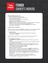
a. ConnectaDVIvideosourcetothetotheInputconnectoronthetransmitterandtheaDVIDisplaytothe
DVI-D INPUT
Ouput connectors on the receiver.
b. Connect unbalanced stereo or mono audio input and an audio output device to the 3.5 mm mini jack audio
AUDIO
ports on both units.
c. IfyouwanttheFOXBOXunitstopassserialdataorcontrolsignals,suchasforserialcontrolofaprojector,
ALARM
Tx Rx 1 2
RS-232
OVER FIBER
connectthemasterdevicetothetransmitterandtheslavedeviceusingtherstthreepolesoftheRS-232
OverFiber/Alarm5-polecaptivescrewconnectorsonbothunits.
NOTE: ForRS-232responses(fromthereceivertothetransmitter),youmustinstallthecableinstep3b and leave
the receiver in normal configuration.
d. Forremotemonitoringofthestatusoftheopticallinks,connectalocallyconstructedorobtaineddeviceto
RS-232
OVER FIBER
ALARM
Tx Rx 1 2
thetwoAlarmpolesoftheunits’RS-232OverFiber/Alarm5-polecaptivescrewconnectors.Thetwopoles
are shorted together when no light is detected.
NOTES:TheAlarmportonthetransmitterreportsthestatusoftheRxlightlink.
The Alarm port on the receiver reports the status of the Tx light link.
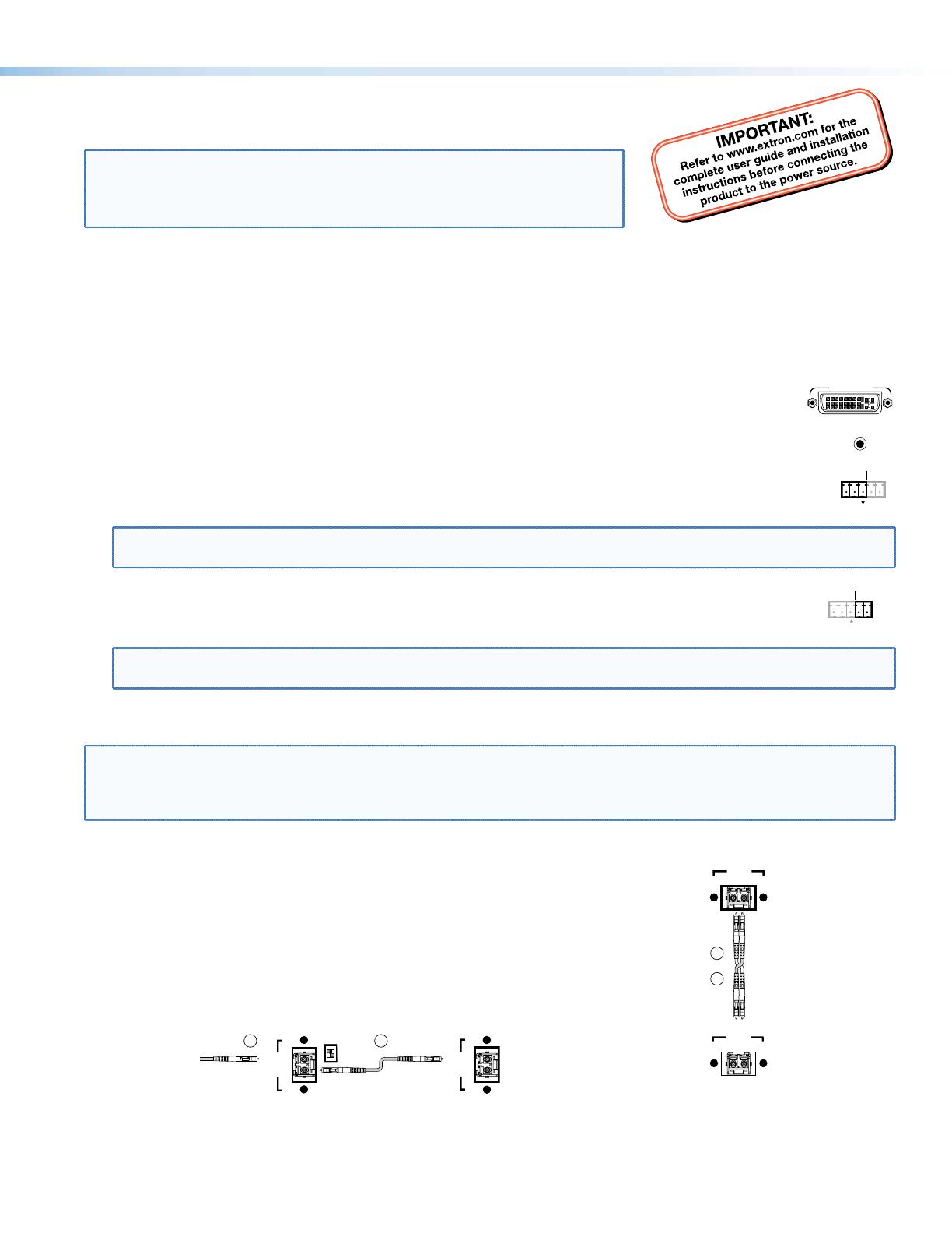
Step 3 — Throughput Connections
NOTE: Youcanconnectthetransmitterandoneormorereceiversinoneofthreeways:
• Oneway(transmittertoreceiver)only,performstep3a.
• Twoway(transmittertoreceiverandreturn),performsteps 3a and 3b.
• Oneway(transmittertoreceiver)withdaisychain(receivertoreceiver),performsteps3a and 3c.
a. ConnectabercablebetweentheTxportonthetransmitterandtheRxporton
the receiver.
OPTICAL
Tx Rx
LINK
LINK
OPTICAL
Tx Rx
LINK
LINK
and
Transmitter
Receiver
3a
3b
b. Ifyouwantthereceivertosendreturnserialdata(suchasresponsesfroma
controlleddevice)tothetransmitter,connectabercablebetweentheTxport
onthereceiverandtheRxportonthetransmitter.
c. Ifyouwantareceivertodaisychaintheopticalsignaltoanotherreceiver(upto
10receiversinadaisychain):
z ConnecttheTxportonthereceivertotheRxportonanotherreceiver.
z SettheModeDIPswitch1uponrstreceiver.
OPTICAL
Tx Rx
LINK
LINK
From Transmitter or
Daisy Chaining Receiver
MODE
12
Receiver
Receiver
3a 3c
OPTICAL
LINK
LINK
Tx Rx
1
FOXBOXDVIPlus•SetupGuide
Step 4 — Remote Connector
Connectahostdevicetoeitherunit’sfrontpanelCongurationconnectorviathe9-pinDto2.5mmminijackTRSRS-232
cablethatisincludedwiththeTXmodeloravailableseparatelyusingpart#70-335-01.RefertotheFOXBOX DVI Plus
UserGuidefordetailedinformationabouttheusingtheSimpleInstructionSet(SIS
)commandsandtheWindows
®
-based
FOX Extender program to set up and operate the transmitter and receiver and to take advantage of the various adjustments
and test patterns available on the FOXBOX units.
Step 5 — Power
Connectusinganexternalpowersupplyasshownontheright.
Control and Indications
Operation
After all receivers, the transmitter, and their connected devices are powered up,
thesystemisfullyoperational.Ifanyproblemsareencountered,verifythatthe
cablesareroutedandconnectedproperlyandthatalldisplaydeviceshaveidenticalresolutionsandrefreshrates.Ifyour
problemspersist,calltheExtronS
3
Sales&TechnicalSupportHotline.
Mode Switch
Mode switch (receiver) —Toconnectthereceivedopticalinputtoanotherreceiverinadaisychainconguration,
MODE
12
set DIP switch 1 to up as shown.
DIPswitch2isnotused.
NOTE: Upto10properly-conguredreceiverscanbeconnectedinadaisychaintoasingletransmitter.
Indications
Tx Link and Rx Link LEDs—Whenlit,thelinkisactive(lightisoutput[Tx]orreceived[Rx]). 
OPTICAL
Tx Rx
LINK
LINK
NOTE: TheLinkLEDsindicatelighttransmissiononly,notwhetherthereisdataencodedintheoptical
link.
Power LED — This LED lights to indicate that power is applied to the unit.
DVI
OVER
TEMP
AUDIO
Over Temp(erature) LED—ThisLEDlightstoindicatethattheunitisoperatingatadangerouslyhigh
temperature(approximately167°F[75°C])andthatequipmentdamageisimminent.
DVI LED — This LED lights on both units when the transmitter detects a signal on its video input. This LED lights on
the receiver when the transmitter detects a DVI video signal.
Audio LED — This LED lights on both units when the transmitter detects a low level audio signal for a short period of time.
It goes dark if the audio signal drops below the minimum threshold for a short period of time.
Power Supply
Output Cord
SECTION A–A
Ridges
Smooth
AA
Captive
Screw
Connector
Tie Wrap
3"
16 (5 mm) Max
.
Extron USA - West
Headquarters
+800.633.9876
Inside USA/Canada Only
+1.714.491.1500
+1.714.491.1517 FAX
Extron USA - East
+800.633.9876
Inside USA/Canada Only
+1.919.863.1794
+1.919.863.1797 FAX
Extron Europe
+800.3987.6673
Inside Europe Only
+31.33.453.4040
+31.33.453.4050 FAX
Extron Asia
+800.7339.8766
Inside Asia Only
+65.6383.4400
+65.6383.4664 FAX
Extron Japan
+81.3.3511.7655
+81.3.3511.7656 FAX
Extron China
+400.883.1568
Inside China Only
+86.21.3760.1568
+86.21.3760.1566 FAX
Extron Middle East
+971.4.2991800
+971.4.2991880 FAX
© 2011 Extron Electronics. All rights reserved. www.extron.com
68-1464-51
Rev B
05 11
2
FOXBOXDVIPlus•SetupGuide(Cont’d)
  • Page 1 1
  • Page 2 2

Extron FOXBOX Rx DVI Plus User manual

Category
Network media converters
Type
User manual
This manual is also suitable for

Extron FOXBOX Rx DVI Plus is a high-performance receiver that provides reliable signal transmission and flexible connectivity options for DVI video, audio, and control signals over fiber optic cabling. With its advanced features, it offers a powerful solution for various applications requiring long-distance signal extension and distribution.

Key capabilities of the Extron FOXBOX Rx DVI Plus:

  • DVI Video Transmission: The receiver accepts DVI video signals from compatible sources and transmits them over fiber optic cables, ensuring high-quality video transmission with resolutions up to 1920x1200.

Ask a question and I''ll find the answer in the document

Finding information in a document is now easier with AI