Page is loading ...

Your Power Solutions Partner
member of The Group
™
Alpha Micro Secure UPS
Installation and Operation Manual


Alpha Micro Secure UPS
Installation and Operation Manual
For technical support, contact Alpha Technologies:
Canada and USA: 1-888-462-7487
International: +1-604-436-5547
Email: [email protected]
Copyright
Copyright © 2010 Alpha Technologies Ltd. All rights reserved. Alpha is a registered trademark of Alpha Technolo-
gies.
No part of this documentation shall be reproduced, stored in a retrieval system, translated, transcribed, or trans-
mitted in any form or by any means manual, electric, electronic, electromechanical, chemical, optical, or other-
wise without prior explicit written permission from Alpha Technologies.
This document, the software it describes, and the information and know-how they contain constitute the propri-
etary, confidential and valuable trade secret information of Alpha Technologies, and may not be used for any
unauthorized purpose, or disclosed to others without the prior written permission of Alpha Technologies.
The material contained in this document is for information only and is subject to change without notice. While
reasonable efforts have been made in the preparation of this document to assure its accuracy, Alpha Technolo-
gies assumes no liability resulting from errors or omissions in this document, or from the use of the information
contained herein. Alpha Technologies reserves the right to make changes in the product design without reserva-
tion and without notification to its users.
Alpha shall not be held liable for any damage or injury involving its enclosures, power
supplies, generators, batteries, or other hardware if used or operated in any manner or
subject to any condition inconsistent with its intended purpose, or if installed or oper-
ated in an unapproved manner, or improperly maintained.
Photographs contained in this manual are for illustrative purposes only. These photo-
graphs may not match your installation.
NOTE:
Operator is cautioned to review the drawings and illustrations contained in this manual
before proceeding. If there are questions regarding the safe operation of this powering
system, contact Alpha Technologies or your nearest Alpha representative.
NOTE:
NOTE:

017-220-B0 Rev 0710
2
Table of Contents
1. Safety ....................................................................................................................................4
1.1 Safety Symbols .................................................................................................................... 4
1.2 General Warnings and Cautions .......................................................................................... 5
1.3 Certications and Compliances ............................................................................................ 6
2. General Description ..............................................................................................................7
2.1 Overview .............................................................................................................................. 7
3. Site Planning .........................................................................................................................9
3.1 Safety Precautions ............................................................................................................... 9
3.2 Electromagnetic Compatibility (EMC) Requirements ........................................................... 9
4. Unpacking Alpha Micro Secure ...........................................................................................10
5. Installation ...........................................................................................................................11
5.1 Transporting and Lifting .......................................................................................................11
5.2 Mounting Options ................................................................................................................11
5.3 Wiring the Alpha Micro Secure ........................................................................................... 15
5.4 Installing and Wiring the Batteries ...................................................................................... 16
5.5 Powering Up the Alpha Micro Secure ................................................................................ 17
6. Operation ...........................................................................................................................18
6.1 Communicating with the Alpha Micro Secure..................................................................... 19
6.2 Communicating with the RS-232 interface ......................................................................... 20
6.3 Using the Main Menu ......................................................................................................... 21
6.4 RS-232 Menu Tree ............................................................................................................. 22
6.5 Operation ........................................................................................................................... 34
6.6 Communicating Via The Intranet or Internet ...................................................................... 55
7. Maintenance .......................................................................................................................58
7.1 Updating the Software ........................................................................................................ 58
7.2 Testing and Replacing the Batteries ................................................................................... 61
7.3 Preventative Maintenance .................................................................................................. 64
8. Troubleshooting ..................................................................................................................65
9. Specications ......................................................................................................................66

3
017-220-B0 Rev 0710
10. Puekert Number and Battery Capacity .............................................................................69
10.1 Introduction ...................................................................................................................... 69
10.2 Determining the Peukert’s Number and Peukert’s Capacity ............................................ 69
10.3 Determining Peukert’s Capacity for Series Parallel Combinations .................................. 69
10.4 Example ........................................................................................................................... 70
10.5 Using the Spreadsheet..................................................................................................... 71
11. Warranty ............................................................................................................................72
11.1 Battery Warranty ............................................................................................................... 72
12. Emergency Shutdown Procedure .....................................................................................73

017-220-B0 Rev 0710
4
1. Safety
SAVE THESE INSTRUCTIONS: This manual contains important safety instructions that
must be followed during the installation, servicing, and maintenance of the product. Keep it in a safe place. Re-
view the drawings and illustrations contained in this manual before proceeding. If there are any questions regard-
ing the safe installation or operation of this product, contact Alpha Technologies or the nearest Alpha representa-
tive. Save this document for future reference.
1.1 Safety Symbols
To reduce the risk of injury or death, and to ensure the continued safe operation of this product, the following
symbols have been placed throughout this manual. Where these symbols appear, use extra care and attention.
The use of ATTENTION indicates specific regulatory/code requirements that may affect the placement of equip-
ment and /or installation procedures.
WARNING!
WARNING presents safety information to PREVENT INJURY OR DEATH to personnel.
Warnings are indicated by a shock hazard icon, the word WARNING, and a rule beneath
which the information appears.
CAUTION!
CAUTION indicates safety information intended to PREVENT DAMAGE to material or
equipment. Cautions are designated with a yellow warning triangle, the word CAUTION,
and a rule beneath which the information appears.
NOTE:
A NOTE provides additional information to help complete a specic task or procedure.
Notes are designated with a checkmark, the word NOTE, and a rule beneath which the
information appears.
HOT!
The use of HOT presents safety information to PREVENT BURNS to the technician or
user.

5
017-220-B0 Rev 0710
1.2 General Warnings and Cautions
You must read and understand the following warnings before installing the Alpha Micro Secure and its compo-
nents. Failure to do so could result in personal injury or death.
• Read and follow all instructions included in this manual.
• Do not work alone under hazardous conditions.
• Only qualified personnel are allowed to install, operate and service this system and its components.
• Use proper lifting techniques whenever handling equipment, parts, or batteries.
• Always assume electrical connections or conductors are live. Switch off all circuit breakers and double-
check connections with a voltmeter before performing installation or maintenance.
• Place warning label(s) on the utility panel to tell emergency personnel a UPS is installed.
• The Alpha Micro Secure uses more than one live circuit. AC power may be present at the outputs even if the
system is disconnected from line or battery power.
• The Alpha Micro Secure’s surface can be very hot to the touch.
• Battery installation and servicing should be done or supervised by personnel knowledgeable about batteries
and their safety procedures.
• If electrolyte splashes on your skin, immediately wash the affected area with water. If electrolyte gets into
your eyes, wash them for at least 10 minutes with clean running water or a special neutralizing eye wash
solution. Seek medical attention at once.
• Neutralize spilled electrolyte with special neutralizing solutions in a “spill kit” or a solution of 1 lb. (0.45 kg) of
baking soda (bicarbonate of soda) in 1 gallon (3.8 L) of water.
• Be extra cautious when connecting or adjusting battery cabling. An improperly connected battery cable or
an unconnected battery cable can result in arcing, fire, or explosion.
• Use new batteries when installing a new unit. Verify that all batteries are the same type with identical date
codes.
• Always replace batteries with ones of identical number, type and rating. Never install old or untested batter-
ies. One sealed lead-acid battery is rated to a maximum voltage of 12 VDC.
• A battery that shows signs of cracking, leaking or swelling must be replaced immediately by authorized per-
sonnel using a battery of identical type and rating.
• Keep the chassis area clear and dust-free during and after installation.
• Keep tools away from walk areas where you or others could fall over them.
• Wear safety glasses when working under any conditions that might be hazardous to your eyes.
• Do not work on the unit or connect or disconnect cables during periods of lightning activity.
• Do not smoke or introduce sparks in the vicinity of a battery.
• Never open or damage the batteries. Released electrolyte is harmful to the skin and eyes. It may be toxic
and hazardous to the environment.
• A battery can present a risk of electrical shock and high short-circuit current. The following precautions
should be observed when working on batteries:
a. Remove watches, rings, or other metal objects.
b. Use tools with insulated handles.
c. Wear rubber gloves and boots.
d. Do not lay tools or metal parts on top of batteries.
e. Disconnect the charging source before connecting or disconnecting battery terminals.
f. Determine if the battery is inadvertently grounded. If inadvertently grounded, remove the source from the
ground. Contact with any part of a grounded battery can result in electrical shock. The likelihood of such
shock can be reduced if the grounds are removed during installation and maintenance (applicable to
equipment and remote battery supplies not having a grounded supply circuit).

017-220-B0 Rev 0710
6
• Never let live battery wires touch the Alpha Micro Secure the enclosure or any other metal objects. This can
cause a fire or explosion.
• Never dispose of batteries in a fire. The batteries may explode. Follow the manufacturer’s directions and
check with your local jurisdictions for safe battery disposal.
• Before attaching the batteries to the Alpha Micro Secure make sure that the polarity is correct.
• If the batteries have been in storage for more than 3 months, recharge them for at least 24 hours and then
test them with a load before installation.
• Each AlphaCell™ battery has a date code, found on the warning label, which must be recorded in the main-
tenance log. If non-Alpha batteries are used, see the manufacturer’s documentation for date code type and
placement.
1.3 Certifications and Compliances
The Alpha Micro Secure has been designed, manufactured, and tested to the requirements of the following na-
tional and international safety standards:
• CAN/CSA-C22.2 No. 107.3-05 – Uninterruptible Power Systems; additional requirements (RD): CAN/CSA-
C22.2 No. 60950-1-03 - Information Technology Equipment - Safety.
• UL 1778 (Edition 4) – Uninterruptible Power Systems; additional requirements (RD): UL 60950-1 (Edition 1) -
Information Technology Equipment - Safety.
• FCC CFR47 Part 15 Class A – This equipment has been tested and found to comply with the limits for a
Class A digital device pursuant to part 15 of the FCC Rules. These limits are designed to provide reasonable
protection against harmful interference when the equipment is operated in a commercial environment. This
equipment generates, uses, and can radiate radio frequency energy and, if not installed and used in ac-
cordance with the instruction manual, may cause harmful interference to radio communications. Operation
of this equipment in a residential area is likely to cause harmful interference in which case the user will be
required to correct the interference at his own expense.

7
017-220-B0 Rev 0710
2. General Description
2.1 Overview
Figure 2 — Alpha Micro Secure Surveillance version
Figure 1 — Alpha Micro Secure Cable version
Batteries
Battery fuse
30 A standard
automotive fuse
Input circuit breaker
Output connector
Front cover LEDs
1 green, 1 red
NEMA 5-15P plug, 120 V
Input power cable not pro-
vided for 230 V application
Batteries
Battery fuse
30 A standard
automotive fuse
Input circuit breaker
RS232 connector,
LEDs, and dry contacts
Input terminal block
Output terminal block
Optional factory in-
stalled Ethernet card

017-220-B0 Rev 0710
8
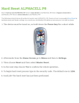
Figure 3 — Output Connectors and Monitoring LEDs
The surveillance version of the Alpha Micro Secure has a bar with monitoring LEDs, an RS-232 connector and
dry contacts for attachment of an external monitoring panel.
Dry Contacts
C2
NO NCC
4 65
C1
NO NCC
1 32
• C1 is the “On Batt” contact,
triggered when the UPS is in
Battery mode and backup battery
power is provided to the load.
• C2 is the “Low Batt” contact,
triggered when the battery voltage
falls below a pre-programmed
setting to indicate the battery is
almost discharged.
• These contacts can be changed
from these factory defaults to
suit your conditions if you have
connected a computer to the unit
Green and Red LEDs
RS-232 Connector
The dry contacts
have a maximum
rating of 1A at 250V.
Microprocessor
UPS
Interior
Normally
Closed (NC)
Normally
Open (NO)
Common (C)
Top view
Bottom View

9
017-220-B0 Rev 0710
3. Site Planning
WARNING!
The Alpha Micro Secure must be installed in a restricted area accessible only by quali-
ed service personnel.
The Alpha Micro Secure must be correctly grounded for proper operation according to
local and national electrical code.
The utility line attached to the Alpha Micro Secure input MUST be protected by a circuit
breaker certied for this use in accordance with the local electrical code.
The AC input and AC output must each have a disconnect device attached. This device
can be a listed branch circuit protection device or a disconnect switch used on AC Line
only. Neutral or ground must never be disconnected by the user except during installa-
tion or maintenance.
3.1 Safety Precautions
• Install the Alpha Micro Secure and batteries in a restricted access location, and on a structure that sup-
ports the total weight.
• The input wiring must reach a suitably grounded power outlet and the load wiring must reach the
Alpha Micro Secures output terminal blocks.
3.2 Electromagnetic Compatibility (EMC) Requirements
Observe the following EMC requirements when setting up the Alpha Micro Secure and its internal equipment:
• All AC mains and external supply conductors must be enclosed in a metal conduit or raceway when speci-
fied by local, national, and/or other applicable government codes and regulations.
• The customer facilities must provide suitable surge protection.

017-220-B0 Rev 0710
10
4. Unpacking Alpha Micro Secure
Follow these guidelines for unpacking the Alpha Micro Secure.
WARNING!
The Alpha Micro Secure is heavy, more than 45 kg (100 lb) with batteries. Use proper
lifting techniques. The lifting and moving should be done by at least two people to avoid
injury.
1. Select a suitable area for unpacking.
2. Store all the packing material and boxes for possible equipment returns.
3. Check the contents in your product package. See “Checking the Package Contents” on this page.
4. Compare the packing slip and the list of parts with the items you received. If the list of parts on your packing
slip does not match the items you received, or any items appear damaged, immediately notify your carrier
agent and the supplier who prepared your shipment.
4.2.1 Checking the Package Contents
Before starting the installation, inspect the package contents and make sure the following standard items as well
as purchased options are included.
Table A — Standard Items
Quantity Item
1
Alpha Micro Secure UPS module.
1
Alpha Micro Secure Installation & Operation manual.
2
4 Phillips-head wood screws.
2 or 4 batteries as ordered.
1
Battery fuse (Standard 30A automotive fuse).

11
017-220-B0 Rev 0710
5. Installation
Once the installation location has been planned and prepared, you are ready to install the Alpha Micro Secure.
There are three steps to setting up the Alpha Micro Secure:
1. Mounting the Alpha Micro Secure.
2. Wiring the Alpha Micro Secure.
3. Installing and wiring the external batteries.
5.1 Transporting and Lifting
WARNING!
To avoid personal injury or damage to the equipment, always use at least two installa-
tion personnel to remove the unit from its container.
Batteries must not be installed until the Alpha Micro Secure enclosure has been secure-
ly set in place at its permanent location. Transporting the unit with batteries installed
may cause a short circuit, re, explosion, and/or damage to the battery pack, enclosure
and installed equipment. Damage caused by improper shipping or transporting a unit
with batteries installed is not covered by the warranty.
5.2 Mounting Options
Choose any of the following four mounting options:
• Mounting to a wall.
• Mounting to a wooden pole.
• Mounting to a steel/concrete pole.

017-220-B0 Rev 0710
12
5.2.1 Mounting to a Wall
The Alpha Micro Secure can be mounted to a wall or to wall studs. The wall or studs should be able to hold a
weight of at least 45.0 lbs (20.4 kg) and they must be plumb and the case mounted so it is level.
Using the case as a template, secure the case to the wall with the 4 Phillips-head wood screws supplied with the
unit.
8.0 Inches (20.3 cm)
12.0 Inches (30.5 cm)
Figure 4 — Wall mounting template

13
017-220-B0 Rev 0710
5.2.2 Mounting to a Wooden Pole
The Alpha Micro Secure can be pole mounted with the optional mounting bracket (Alpha Kit# 740-751-21). It al-
lows you to mount to either a vertical or horizontal, steel, concrete or wooden pole.
Procedure
To bolt the UPS to the pole you need the optional mounting bracket and 2, ½" bolts (not provided) to fit the pole.
1. Drill holes into the pole to fit the bolts.
2. Attach the bracket to the pole.
3. Secure the UPS enclosure to the mounting bracket with the 2 mounting screws and 2 nuts provided with the
kit.
Figure 5 — Mounting to a wooden pole

017-220-B0 Rev 0710
14
5.2.3 Mounting to a steel or concrete pole
To strap mount the Alpha Micro Secure to the pole you need the optional mounting bracket and 2, ½" straps
(Band-It #C20499 straps, #C00369 Tool and #C25499 Buckle or equivalent).
1. Attach the straps to the mounting bracket.
2. Attach the bracket to the pole.
3. Secure the UPS enclosure to the mounting bracket with the 2 mounting screws and 2 nuts provided with the
kit.
Figure 6 — Mounting to a steel or concrete pole

15
017-220-B0 Rev 0710
5.3 Wiring the Alpha Micro Secure
5.3.1 Tools and Materials Required
• Slotted-tip screwdrivers for tightening screws on terminal blocks.
• DC voltmeter.
• Maximum of 12 AWG wire for wiring the input and output terminal blocks.
• If used, maximum of 16 AWG wire for wiring the dry contact terminal blocks.
Procedure
There are two different versions of the Alpha Micro Secure. For the surveillance version, you may have to connect
the dry contact terminal block outputs and the RS-232 connector depending on your requirements.
1. Connect the load wiring to the output terminal block (surveillance version) as labeled. Torque to 7.0 lb-in (0.8
Nm). For the cable TV version, connect the load cable to the output cable connector.
2. On the surveillance version, if used, connect the dry contact terminal blocks and the RS-232 or Ethernet
connectors. If using a conduit, drill a 1/2" hole to attach a matching conduit.
3. Wire the input terminal block according to its label. Torque to 7.0 lb-in (0.8 Nm).
The cable version has a 6-ft (2 m) permanently connected input power cable with a NEMA 5-15P plug for 120 V
application. For 230 V application, connect the line power to the input terminal block through the provided 1/2"
knockout hole.
The standard Alpha Micro Secure unit does not have an on/off switch. Whenever the
UPS senses battery or line power, it is active and power is present at the output. Before
starting, make sure line power is turned off and that the UPS’s battery fuse is removed.
WARNING!
To Load
Drill hole
to attach
incoming
conduit
1
3
From Line
Power
Input
terminal
block
Dry contact
terminal
block
Output
terminal
block
Figure 7 — Wiring the Alpha Micro Secure

017-220-B0 Rev 0710
16
Battery #3
Battery #1
Battery #4
Battery #2
Battery
Fuse
Figure 8 — Battery Locations
5.4 Installing and Wiring the Batteries
WARNING!
Before proceeding, verify the line wire is attached to the line terminal block, the ground
wire is attached to the ground terminal block and the neutral wire is attached to the neu-
tral terminal block to prevent accidental shocks or electrocutions.
Make sure the battery fuse is removed before wiring the batteries.

17
017-220-B0 Rev 0710
Procedure
1. Install the 4 batteries and wire them up as shown in Figure 8 and Figure 9.
If using only 2 batteries, install them in the Battery #1 and Battery #2 positions and wire them up as shown in
Figure 6.2, except the wires to Battery #3 and #4 are not used.
2. Use a DC voltmeter to verify the battery string’s polarity and voltage (24 VDC). Perform troubleshooting if
necessary.
RED
RED
BLACK
BLACK
If using only 2
batteries, ignore
these connections.
Figure 9 — Battery wiring diagram
5.5 Powering Up the Alpha Micro Secure
Make sure that the Line power is qualified but turned off and the batteries are fully charged.
Procedure
1. Install the battery fuse by snapping it quickly into its fuse holder. Make sure it is firmly secured in the mount.
You may hear a buzzing sound or see sparks when installing the fuse. This is normal and will not damage the
UPS.
2. Switch on the Line power.
3. Ensure the LEDs are working. See LED status table below.
4. When Line power is first applied, both LEDs illuminate and then only the green light remains on if the UPS is
in Line mode.
Table B — LED status description
LED Status Description
GREEN OFF The UPS’s inverter is turned off. Line power goes straight to the load.
GREEN ON The UPS is turned on. Line power is provided to the load.
GREEN FLASHING The UPS’s inverter is on. Backup battery power is provided to the load.
RED ON OR FLASHING The UPS has a malfunction. See the troubleshooting table below.

017-220-B0 Rev 0710
18
6. Operation
The following subsections describe the operation of the Alpha Micro Secure:
• Communicating with the Alpha Micro Secure.
• Communicating with the RS-232 interface.
• Adjusting and controlling the Alpha Micro Secure
• Viewing the 100-event log.
• Communicating with the Alpha UPS Monitor.
/