WOOSIM Porti-M100V Operating instructions
- Type
- Operating instructions
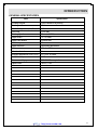
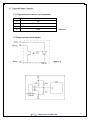
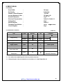
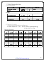
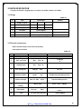
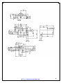
WOOSIM Porti-M100V is a high-quality thermal printing mechanism designed for industrial environments and portable applications. With a printing speed of up to 50 mm/s and a resolution of 8 dots/mm, it can produce clear and legible text and graphics. The Porti-M100V also features a paper detection photo-sensor and a long life of 100 km of printed paper.
Some potential use cases for the Porti-M100V include:
- Industrial environments: The Porti-M100V can be used in a variety of industrial settings, such as weight control systems, safety systems, and medical applications.
- Portable applications: The Porti-M100V is also well-suited for portable applications, such as mobileprinters and point-of-sale systems.


-
 1
1
-
 2
2
-
 3
3
-
 4
4
-
 5
5
-
 6
6
-
 7
7
-
 8
8
-
 9
9
-
 10
10
-
 11
11
-
 12
12
-
 13
13
-
 14
14
-
 15
15
-
 16
16
-
 17
17
-
 18
18
-
 19
19
-
 20
20
-
 21
21
-
 22
22
-
 23
23
-
 24
24
-
 25
25
-
 26
26
-
 27
27


WOOSIM Porti-M100V Operating instructions
- Type
- Operating instructions
WOOSIM Porti-M100V is a high-quality thermal printing mechanism designed for industrial environments and portable applications. With a printing speed of up to 50 mm/s and a resolution of 8 dots/mm, it can produce clear and legible text and graphics. The Porti-M100V also features a paper detection photo-sensor and a long life of 100 km of printed paper.
Some potential use cases for the Porti-M100V include:
- Industrial environments: The Porti-M100V can be used in a variety of industrial settings, such as weight control systems, safety systems, and medical applications.
- Portable applications: The Porti-M100V is also well-suited for portable applications, such as mobileprinters and point-of-sale systems.
Ask a question and I''ll find the answer in the document
Finding information in a document is now easier with AI
Related papers
-
WOOSIM Porti-M100H Operating instructions
-
-
-
-
-
-
-
-
-
Other documents
-
CableWholesale 30W1-00200 Datasheet
-
Seiko LTPD345D Technical Reference
-
BIXOLON SMP690/691 User manual
-
Fujitsu FTP-628MCL451 User manual
-
Seiko Instruments LTP F Series User manual
-
-
-
-
Citizen CL-S703 User manual
-