
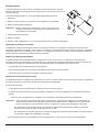
WARNING: Improper installation, adjustment, alteration, service or maintenance
can cause injury or property damage. Refer to this manual. For as-
sistance or additional information, contact a qualied installer, service
agency, or the gas supplier.
FOR YOUR SAFETY
Do not store or use gasoline or other ammable vapors and liquid in the
vicinity of this or any other appliance.
FOR YOUR SAFETY
If you smell gas:
1. Open windows
2. Don’t touch electrical switches.
3. Extinguish any open ame.
4. Immediately call your gas supplier.
NORCOLD, Inc.
P.O. Box 4248
Sidney, OH 45365-4248
Part No. 632229A (10-07)
English
Norcold Customer Support Dept.
Telephone: 800-543-1219
Fax: 937-497-3183
Web Site: www.norcold.com
Owner’s Manual
for the 2117X series of RV Refrigerators
The letter “X”, in the model numbers above, stands for a letter or numeral which means a
refrigerator option.
!

Owner’s Manual 2
Table of Contents
For dened warranty terms, please see the one page warranty statement included in the product information packet.
Safety Awareness ........................................................................................................................................................................................ 3
Safety Instructions ....................................................................................................................................................................................... 3
About Your Refrigerator ............................................................................................................................................................................... 3
Storage volume .................................................................................................................................................................................... 3
Leveling ................................................................................................................................................................................................ 3
Operation during travel .........................................................................................................................................................................
4
Food compartment ...............................................................................................................................................................................
4
Freezer compartment ........................................................................................................................................................................... 4
Door handles ........................................................................................................................................................................................
4
Moveable door seal ..............................................................................................................................................................................
4
Crispers and beverage bin ................................................................................................................................................................... 4
Adjustable cantilever shelves ...............................................................................................................................................................
6
Adjustable food fences .........................................................................................................................................................................
7
Door bins ..............................................................................................................................................................................................
7
Door alarm
........................................................................................................................................................................................... 7
Interior light
........................................................................................................................................................................................... 8
Moisture reduction heaters ...................................................................................................................................................................
8
Automatic defrost system .....................................................................................................................................................................
8
Backup operating system .....................................................................................................................................................................
8
Temperature switch monitor .................................................................................................................................................................
9
Operating the Refrigerator Controls ............................................................................................................................................................ 9
Control panel ........................................................................................................................................................................................
9
Automatic mode operation .................................................................................................................................................................
10
Removing air from the propane gas supply lines ...............................................................................................................................
10
Set the controls to automatic mode operation .....................................................................................................................................
11
Set the controls to manual mode operation
.........................................................................................................................................11
Effects of High Altitude on Propane Gas Operation ...................................................................................................................................11
Ice Maker ....................................................................................................................................................................................................11
Refrigerator Care Checklist ....................................................................................................................................................................... 13
Cleaning ....................................................................................................................................................................................................
13
Interior ................................................................................................................................................................................................ 13
Metal doors ................................................................................................................................................................................................ 13
Door Sealing .............................................................................................................................................................................................. 14
Refrigerator Storage .................................................................................................................................................................................. 14
Ice Maker Storage ..................................................................................................................................................................................... 14
Refrigerator Maintenance Checklist ......................................................................................................................................................... 15
Refrigerator Maintenance .......................................................................................................................................................................... 16
Gas ame appearance .......................................................................................................................................................................
16
Remove and clean the burner orice .................................................................................................................................................
16
Remove the Refrigerator ........................................................................................................................................................................... 17
Reinstall the Refrigerator ........................................................................................................................................................................... 18
Replacement Parts .................................................................................................................................................................................... 18
Fault Codes ............................................................................................................................................................................................... 19
Wiring Diagram and Pictorial ..................................................................................................................................................................... 20
Ice Maker Wiring Diagram and Pictorial .................................................................................................................................................... 21

Owner’s Manual 3
Safety Instructions
Safety Awareness
Read this manual carefully and understand the contents before
you use the refrigerator.
Be aware of possible safety hazards when you see the safety
alert symbol on the refrigerator and in this manual. A signal word
follows the safety alert symbol and identies the danger of the
hazard. Carefully read the descriptions of these signal words to
fully know their meanings. They are for your safety.
WARNING: This signal word means a hazard, which if
ignored, can cause dangerous personal injury, death, or
much property damage.
CAUTION: This signal word means a hazard, which if
ignored, can cause small personal injury or much property
damage.
WARNING:
- The storage of ammable materials behind or around
the refrigerator creates a re hazard. Do not use the
area behind the refrigerator to store anything, especially
ammable materials (gasoline, cleaning supplies, etc.)
- Do not remove the round ground prong from the
AC power cord of the refrigerator or the ice maker
(optional). Do not use a two prong adapter or an
extension cord with either AC power cord.
- A circuit overload can result in an electrical re if the
wires and/or fuses are not the correct size. Use only
the wire and fuse sizes as writtten in the “Installation
Manual”.
- Incorrect installation, adjustment, change to, or
maintenance of this refrigerator can cause personal
injury, property damage, or both. Have service and
maintenance work done by your dealer or by an Norcold
authorized service center.
- Disconnect both the AC and DC power sources before
doing any maintenance work on the refrigerator. All
service work on this refrigerator must be done by a
qualied service technician.
- Do not bypass or change the refrigerator’s electrical
components or features.
- When you discard an appliance, remove all doors to
prevent accidental entrapment and suffocation.
!
!
!
- Do not spray liquids near electrical outlets, connections,
or the refrigerator components. Many liquids are
electrically conductive and can cause a shock hazard,
electrical shorts, and in some cases re.
- The refrigerator cooling system is under pressure. Do
not try to repair or to recharge a defective cooling
system. The cooling system contains sodium chromate.
The breathing of certain chromium compounds can
cause cancer. The cooling system contents can cause
severe skin and eye burns, and can ignite and burn with
an intense ame. Do not bend, drop, weld, move, drill,
puncture, or hit the cooling system.
- At regular intervals, make sure that the refrigerator
ue the burner, the vent areas, and the ventilation air
pathway between the vents are completely free from
any ammable material or blockage. After a period of
storage, it is especially important to check these areas
for any ammable material or blockage caused by
animals.
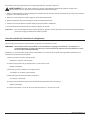
CAUTION:
- The rear of the refrigerator has sharp edges and
corners. To prevent cuts or abrasions when working on
the refrigerator, be careful and wear cut resistant gloves.
!
About Your Refrigerator
Storage Volume:
This refrigerator is made for storage of foods and frozen food and
for making ice.
Total capacity 17.0 cubic feet
Freezer Compartment 5.37 cubic feet
Fresh Food Compartment 11.67 cubic feet
Leveling:
CAUTION: The refrigerator is made to operate within
3° off level side-to-side and 6° off level front-to-back (as
looking at the front of the refrigerator). Operating it at more
than these limits can cause damage to the cooling system
and create a risk of personal injury or property damage.
Make sure the vehicle is level before you operate the
refrigerator.
Operation during travel:
While the refrigerator should be level when the vehicle is
stopped, performance during travel is not usually effected.
!

Owner’s Manual 4
Food compartment:
Start up the refrigerator (see “Operating the Refrigerator Controls”)and let it
cool for eight hours before loading with food. If the refrigerator does not start
to cool down after about two hours, contact your dealer or a Norcold authorized
service center.
For the best cooling performance:
- Do not position food items so that they cause a blockage of the openings
at the sides and the rear of the shelves. The openings allow air to circulate
freely inside the compartment.
- Cover all liquids and moist foods.
- Let all hot foods cool before putting them in the refrigerator.
- Do not open the door any longer than necessary.
Freezer compartment:
The freezer compartment is made to keep pre-frozen food frozen and not to quick freeze food.
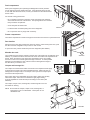
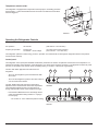
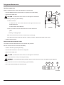
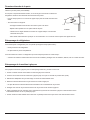
Door handles:
During travel, the door latch prevents the door from opening. When closing each door, push
the door toward the refrigerator until you hear a “click” sound.
To open each door, pull the handle away from the refrigerator (See Art0812).
Movable door seal:
The movable door seal [134] is located on the left door of the fresh food compartment (See
Art0813). It provides the correct seal when both doors of the fresh food compartment are
closed. When the left door of the fresh food compartment opens, the movable
door seal moves so that it is at against the edge of the door. To avoid possible
damage to the movable door seal, make sure that it is at against the edge of
the door before you close the door
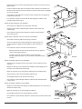
Crispers and beverage bin:
The crispers are located at the bottom of the fresh food compartment and supply
a storage area to preserve fruit and vegetable freshness. Make sure that you
always push the crispers fully in. The crisper covers open as the crispers open
and close as the crispers close.
Each crisper also has an adjustable vent that is used to adjust the humidity
inside each crisper. Move each vent toward the right (high humidity)
for most vegetables or toward the left (low humidity) for most fruits (See
Art01834).
The crispers, crisper covers, beverage bin, and beverage bin cover are
removable for cleaning.
NOTE: Do not wash the crispers, crisper covers, beverage bin, or
beverage bin cover in a dishwasher. These parts are not
dishwasher safe.
70
Art01812
134
Art01813
Art01834
Art01824
135
197
71

Owner’s Manual 5
To remove the crisper covers (See Art01824):
- With the crisper closed, lift the crisper cover[135] to the fully raised position.
- Locate the hinge pins[71] that are part of the crisper cover rails [197].
- Push the front of one of the crisper cover rails inward toward the crisper so you can
lift that side of the crisper cover off of the hinge pin.
- Slide the opposite side of the crisper cover off of the other hinge pin.
- To reinstall the crisper covers, do this procedure in the opposite order.
To remove the crispers (See Art01826):
- Pull each crisper forward until it reaches the “stop” position.
- Lift up on the front of the crisper [a] and continue to pull the crisper out [b].
- To reinstall the crispers, do this procedure in the opposite order.
To remove the beverage bin and beverage bin cover (See Art01827):
- Pull the beverage bin [198] forward [c] and remove.
- Pull the beverage bin cover [199] forward [c] until it disengages from
the bottom full shelf [200] with a “snap”.
- To reinstall the beverage bin cover:
- Align the rear of the beverage bin cover with the center brackets of
the bottom full shelf.
- Push the beverage bin cover back into the bottom full shelf until it
engages with a “snap”.
To remove the bottom full shelf (See Art012828):
- Remove the crisper covers, the crispers, the beverage bin and the
beverage bin cover.
- Locate the two (2) screws [41] that attach the bottom full shelf [200] (one screw
is on the bottom of each side).
- Remove and save the screws and the plastic spacers [201].
- Using both hands, lift the front of the bottom full shelf up [d].
- Pull the bottom full shelf up and out [e].
- To reinstall the bottom full shelf, do this procedure in the opposite order.
To remove the top full shelf (See Art01829):
- Locate the screws that attach the plastic clips [202] (one screw is on the
bottom of each side).
- Remove and save the screws and the plastic clips.
- Pul the top full shelf forward [203] to remove.
- To reinstall the top full shelf, do this procedure in the opposite order.
Art01826
a
b
Art01827
198
199
200
c
Art01828
201
41
d
e
200
A
rt01829
202
203

Owner’s Manual 6
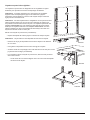
Adjustable cantilever shelves:
The cantilever shelves of the refrigerator and freezer are easily adjustable to
meet your food storage needs.
NOTE: The top shelf on the left side of the freezer holds the ice storage bin for
the automatic icemaker. Do not move or remove this shelf when the ice maker
is in use.
NOTE: The half shelves in the refrigerator are not all the same depth. They
are designed to give clearance for the items in the door bins. The upper
shelves will ONLY t into the upper area [204] of the support rails and the
lower shelves will ONLY t into the lower area [205] of the support rails (See
Art01835). DO NOT try to put a shelf where it will not t.
To remove a cantilever shelf (See Art01831):
- Locate the shelf retainer [54] on the bottom of each shelf.
NOTE: Do not remove the screw in the shelf retainer.
- Loosen the screw [41] in the shelf retainer between 2-3 turns.
- Slide the shelf retainer toward the front [f] of the shelf.
- Lift the front of the shelf up [d] and pull the shelf up and out [e] of the sup-
port rails( See Art01832).
- To reinstall the cantilever shelf, do this procedure in the opposite order.
- The round head of the screw should align with the round recess in the shelf
retainer.
Art01835
204
205
d
Art01832
e
Art01831
41
54
f

Owner’s Manual 7
Adjustable food fences:
The cantilever shelves have adjustable food fences to help keep food items
in place while the vehicle is moving. You may position the food fences from
front to back on the shelf or store them at the front of the shelf when not in use.
To change the position of a food fence (See Art01833):
- Pull up on both ends [g] of the food fence wire [188] until it is free to rotate
toward the front of the shelf.
- Holding both ends of the food fence wire, slide the food fence toward the
front or the rear [h] as you wish.
- With the food fence wire in a vertical (straight up) position, push both sides
of the food fence wire down until it “snaps” into the locked position.
To store the food fence (See Art01833):
- Pull up on both sides of the food fence wire [188] until it is free to
rotate toward the front of the shelf.
- Slide the food fence to the very front of the shelf.
- Rotate the food fence wire forward [j] so that it hangs down in
front of the cantilever shelf.
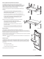
Door bins:
You may put the small door bins [52] of the freezer and fresh food
compartment in a location that best meets your needs. You must put
the large door bins in the lowest positions or else the large door bins
will touch the shelves and the doors wil not close (See Art1815).
To remove the bins, lift them over the locator and pull them forward.
To install the bins, push them onto the locator.
NOTE: Do not wash the door bins in a dishwasher. The door bins are not dishwasher safe.
Door alarm:
The refrigerator has an alarm to alert you if the fresh food compartment door is not closed. The
refrigerator continues to operate, but if the fresh food compartment door is open and the interior
light remains on for two minutes:
- An audible alarm starts.
- “dr” appears in the center display.
- The interior light automatically turns off.
Close the door to silence the alarm.
Art01815
52
Art01833
188
206
g
g
h
h
Art01836
j
j

Owner’s Manual 8
Interior light:
The interior light is at the top of the fresh food compartment. It comes on when the
refrigerator is ON and the door is open. To replace the bulb:
1. Remove the DC power supply wires from the power board at the rear of the refrigerator.
2. Remove the cover [57] by pulling it toward the front of the refrigerator (See Art00988).
3. Remove the light bulb [58] from the holder [59].
NOTE: Use only a GE#214-2 bulb as the replacement bulb. This bulb is available at most
retail automotive parts centers.
4. Install the replacement bulb.
5. Install the cover.
6. Connect the DC power supply wires to the power board at the rear of the refrigerator.
Moisture reduction heaters:
The refrigerator has heaters that prevent moisture from forming on the center divider between the two doors and the perimeter of
the freezer compartment, and on the movable door seal. The heaters operate only when the refrigerator is ON and the DC power is
sufcient. The heater in the movable door seal also only operates when both doors of the fresh food compartment are closed.
Automatic defrost system:
The automatic defrost system will defrost the refrigerator at least daily. The refrigerator controls the actual time between defrost
cycles. The time between defrost cycles depends on the temperatures inside the refrigerator compartments and on the cooling system
performance. The refrigerator will defrost more frequently with:
- higher outside temperature and humidity.
- the storage of non-sealed fresh foods or warm foods.
- longer periods of time that the door(s) are open.
Backup operating system:
This refrigerator has a backup operating system. The backup operating system allows the refrigerator to continue to cool if the
temperature sensor of the refrigerator should fail.
If this failure occurs:
- The refrigerator automatically changes to the backup operating system.
- The backup operating system can overfreeze or thaw the contents of the freezer and the fresh food compartment.
- Make sure the temperatures of the freezer and the fresh food compartment are satisfactory.
NOTE: If you open the door(s) too often, the temperatures inside the freezer and fresh food compartment do not become stable.
Allow the refrigerator to operate for about one hour after each adjustment change before you examine the contents.
The number “9” is the coldest temperature setting.
- If the temperature is too warm, push and hold the SET TEMP button to raise the temperature setting by one number.
- If the temperature is too cold, push and hold the SET TEMP button to lower the temperature setting by one number.
- Have the refrigerator serviced by your dealer or a Norcold authorized Service Center as soon as possible.
Art00988
57
58
59

Owner’s Manual 9
Operating the Refrigerator Controls
AC Operation 120 volts AC (108 volts min.-132 volts max.)
Propane gas operation: Propane gas (11 inches water column pressure)
12 volts DC - control voltage (10.5 volts min. - 15.4 volts max.)
The refrigerator operates on these energy sources. Operation out of these limits can damage the refrigerator electrical components
and will void the warranty.
Control panel:
The refrigerator control panel (See Art01809 and Art01811) is between the freezer compartment and the fresh food compartment. To
maintain the operating control functions of the refrigerator, a 12 volt DC power supply is necessary. The refrigerator receives DC power
from the 12 volt system of the vehicle; either an auxillary battery, a converter, or the vehicle engine battery.
The ON / OFF button [30] starts and shuts down the
refrigerator:
- To turn on the refrigerator, push and release the ON /
OFF button.
- To turn off the refrigerator, push the ON / OFF button for
one second and then release.
The SET TEMP button [32] controls the temperature
adjustment of the freezer and the fresh food compartment.
The temperature adjustment that you select does not
change if the operation mode of the refrigerator changes.
- Push the SET TEMP button and a red triangle shows
under the temperature setting numbers “1-9” [187] in
the LCD [107].
- The number “9” is the coldest temperature setting.
Art01809
30 31
107
32 184
Art01811
185 186
187
33
Temperature switch monitor:
The refrigerator is equipped with a temperature switch [142] for overheating protection
(See Art01851) . A Norcold authorized service technician can determine if this switch
has been triggered.
Art01851
142

Owner’s Manual 10
- Push and hold the SET TEMP button and the temperature setting changes.
- Release the SET TEMP button when the temperature setting that you wish appears.
The MODE button [31] controls the operation mode of the refrigerator:
- Push and hold the MODE button and each of the operating modes of the refrigerator are shown by red triangles.
- There is one automatic mode of operation and two manual modes of operation.
- When the mode of operation that you wish shows in the LCD [107], release the MODE button.
NOTE: To see the LCD at full brightness, press the light button [184]
Automatic mode operation:
When the refrigerator is in the automatic mode, it automatically uses the most efcient energy source that is available for operation.
During operation, if a more efcient energy source becomes available, the refrigerator controls change from the current energy source
to the more efcient energy source as follows:
- The rst choice is AC operation if 120 volts AC is available to the refrigerator.
- The second choice is propane gas operation if 120 volts AC is not available to the refrigerator.
Removing air from the propane gas supply lines:
For safety reasons, the burner is made to ignite on propane gas within a specied amount of time. When starting the refrigerator for
the rst time, after storage, or after replacing propane gas tank, the propane gas supply lines can have air in them. Due to the air in the
gas supply lines, the burner may not ignite on propane gas within the specied amount of time.
To remove the air from the propane gas supply lines:
- Make sure that the valve of the propane gas tanks(s) is open.
- Push the ON / OFF button to turn the refrigerator on.
- Push and hold the MODE button until NO red triangle shows under the mode symbol and a red triangle shows under the gas ame
part of the mode indicator and then release.
- This means that the refrigerator is operating on propane gas.
- If the air in the propane gas supply lines prevents the burner from ignition on propane gas, the fault codes “no” and then “FL”
will appear in the center display and you will hear an alarm sound.
- Push and hold the ON / OFF button for one second and then release to silence the alarm.
- Push the ON / OFF button to turn the refrigerator on.
- The refrigerator will start a 30 second trial for ignition.
- During the 30 second trial for ignition, the refrigerator controls open the gas safety valve and the igniter makes sparks.
- When no fault code shows, this means that the refrigerator is operating on propane gas in the manual mode.
- At this time, all of the air is removed from the propane gas supply lines and you may select automatic mode of operation if you
wish.
- Depending on how much air may be in the propane gas supply lines, you may need to repeat the 30 second trial for ignition two or
three times.
- If the burner does not ignite on propane gas after two or three attempts, stop and consult your local dealer or an authorized
Norcold Service Center.

Owner’s Manual 11
Set the controls to automatic mode operation:
- Push the ON / OFF button to turn the refrigerator on.
- Push and hold the MODE button until a red triangle shows under the mode symbol [185] and then release.
- If 120 volts AC is available to the refrigerator:
- A second red triangle shows under the electric plug part of the mode indicator [186].
- This means that the refrigerator is operating on AC electric.
- If 120 volts AC is not available to the refrigerator:
- A second red triangle shows under the gas ame part of the mode indicator [186].
- This means that the refrigerator is operating on propane gas.
- If neither 120 volts AC nor propane gas is available to the refrigerator:
- The fault codes “no” “AC” and then “no” “FL” show in the center display [33] of the LCD and an audible alarm sounds.
If an energy source is available to the refrigerator, but is not operating correctly:
- A fault code shows in the center display.
- The refrigerator controls try to change to a less efcient energy source.
- If a less efcient energy source is not available:
- An audible alarm starts.
- A fault code shows in the center display.
- Refer to the “Fault Codes” section of this manual.
Set the controls to manual mode operation:
- Push the ON / OFF button to turn the refrigerator on.
- Push and hold the MODE button until NO red triangle shows under the mode symbol and a red triangle shows under the electric
plug part of the mode indicator [186] and then release.
- This means that the refrigerator is in manual mode and is operating on AC electric.
- Push and hold the MODE button until NO red triangle shows under the mode symbol and a red triangle shows under the gas ame
part of the mode indicator [186] and then release.
- This means that the refrigerator is in manual mode and is operating on propane gas.
Effects of High Altitude on Propane Gas Operation
When you operate the refrigerator on propane gas at altitudes higher than 5500 feet above sea level:
- You may experience reduced cooling performance of the refrigerator.
- You may experience burner outages.
To avoid these possible problems, Norcold recommends that you operate the refrigerator on AC when at altitudes higher than 5500 feet
above sea level.

Owner’s Manual 12
Ice Maker
The ice maker is fully automatic and will operate in ambient temperatures as low as 0° F. To allow operation at temperatures between
0° F and 32° F., the ice maker has a heater on the solenoid water valve and on the water line between the solenoid valve and the ice
maker. At temperatures below 0° F, store the ice maker as written in the “Ice Maker Storage” section of this manual.
CAUTION: The water line heater does not protect the water supply line from the vehicle shut off valve to the solenoid valve on
the back of the refrigerator.
When the freezer temperature of the refrigerator is low enough, the ice maker opens the water solenoid valve and lls the mold. The
ice maker ejects the frozen ice into a storage bin. As the storage bin lls, the ice raises the shut-off arm until it turns off the ice maker.
As you use the ice and lower the ice level in the storage bin, the shut-off arm also lowers. This turns the ice maker ON and begins the
process of making ice.
The ice maker operates on:
- Cold potable water at a pressure of 15 psi - 125 psi.
- 120 Volts AC (108 VAC min. - 132 VAC max.).
Ice maker operation:
1. Make sure the ice maker AC power cord is plugged into a receptacle.
2. Open the water shut off valve of the vehicle.
NOTE: Make sure that the ice maker arm can move freely and does not touch the frozen foods in the
freezer.
3. Push the ice maker arm down to the ON position [60] (See Art01015).
CAUTION: If you operate the refrigerator without connecting the water supply line and/or
opening the water shut off valve of the vehicle, make sure the ice maker arm is up in the OFF
position.
4. Allow the freezer to cool enough and ice production will begin to ll the storage bin [61].
NOTE: New plumbing connections and/or impurities in the water supply line after winterizing can cause the rst ice to be discolored or
have an odd avor.
5. To stop the ice maker, push the ice maker arm up to the OFF position [62].
!
!
Art01015
60
62
61

Owner’s Manual 13
Interior:
Clean the inside of the refrigerator as often as necessary to avoid food odors:
- Remove all food from the refrigerator.
NOTE: Do not use abrasive cleaners, chemicals, or scouring pads because they can damage the interior of the refrigerator.
- Wash the interior with a mild cleaner or a solution of liquid dish detergent and warm water.
- Rinse with a solution of baking soda and clean water.
- Dry with clean cloth.
- Put all food in the refrigerator.
Metal doors:
To clean the metal doors:
- Wash the doors with a mild cleaner or a solution of liquid dish detergent and warm water.
- Rinse with clean water.
- Dry with clean cloth.
NOTE: Do not use abrasive cleaners, chemicals, or scouring pads because they can damage the metal doors.
Cleaning
Refrigerator Care Checklist
Your refrigerator will give you years of trouble free service if you do these simple checks every three to six months:
- Keep the food compartment and the freezer clean. See “Cleaning”.
- Make sure the door seals correctly. See “Door Sealing“.
- Be aware of any cooling changes that are not because of weather, loading, or gas control changes. If changes occur, contact your
dealer or service center.
- Make sure the gas supply is propane gas only and not butane or a butane mixture.
- When in propane gas operation, examine the appearance of the ame. See “Gas Flame Appearance”.
- Make sure the air ow in the lower intake vent, through the refrigerator coils and condenser, and out the upper exhaust vent is not
blocked or decreased.
- Make sure the area behind the refrigerator is clear. Do not use the area behind the refrigerator for storage of anything, especially
combustible materials, especially gasoline and other ammable vapors and liquids.

Owner’s Manual 14
Ice Maker Storage
To prepare the ice maker for seasonal storage:
1. Close the vehicle water supply valve to the ice maker.
2. Push the ice maker arm up until it locks into the OFF position.
3. Remove the garden hose adapter from the water solenoid valve.
4. Remove the ice maker water line from the water solenoid valve
- Do not unwrap the water line heater wires from around the water solenoid valve.
5. Drain all of the water from both the water supply line and the ice maker water line.
6. Put the end of the water supply line, the end of the ice maker water line, and the water solenoid valve each into a clean plastic bag.
7. Use tape to close each plastic bag around the water lines and the water solenoid valve.
Door Sealing
Check the seal of the doors (See Art00980).
If a door does not seal correctly, excess frost will collect inside the refrigerator. Make sure the
doors seal correctly:
- Close each door on a piece of paper that is about the size and thickness of a dollar bill.
- Gently pull the paper.
- You should feel a slight drag between the gasket and the cabinet.
- Do this on all four sides of the door.
- If you do not feel a slight drag on the paper, the door does not seal correctly.
- Have your dealer or an authorized Norcold Service Center correct the seal of the door.
Refrigerator Storage
Before the refrigerator is stored for an extended (seasonal) period of time:
- Clean the interior of the refrigerator.
- Do not close the doors completely.
If the refrigerator is stored for an extended period of time, before start up:
- Make sure there are no obstructions in the vents, the ventilation air pathway, the burner, the orice, or the ue area.
Art00980

Owner’s Manual 15
Refrigerator Maintenance Checklist
Read and understand the following maintenance sections of this manual.
NOTE: Norcold is not responsible for installation, adjustment, alteration, service, or maintenance performed by anyone other
than a qualied RV dealer or a Norcold authorized service center.
Have a qualied RV dealer or a Norcold authorized service center do these annual safety and maintenance checks:
- Examine the gas supply lines for leaks.
- Replace or repair if needed.
- Make sure the propane gas pressure is 11 inches water column.
- Adjust if needed.
- Make sure the combustion seal is complete and intact.
- Replace or repair it if needed.
- Make sure the burner and the burner orice are clean.
- Clean if needed.
- Make sure the electrode is clean and the spark gap is 1/8 - 3/16 inch.
- Adjust if needed.
- Make sure the AC voltage is 108 -132 volts and the DC voltage is 10.5 - 15.4 volts.
To use the ice maker after seasonal storage:
CAUTION: Do not operate the ice maker when the ambient air temperature is 0° F. or lower. Damage to the water solenoid
valve and the water supply line can occur.
1. Remove the tape and plastic bags from the end of the water supply line, the end of the ice maker water line, and the water solenoid
valve.
2. Connect the ice maker water line to the water solenoid valve.
3. Connect the garden hose adapter to the water solenoid valve.
4. Push the ice maker arm down into the ON position.
5. Open the vehicle water supply valve to the ice maker.
NOTE: You should discard and not use the rst two batches of ice cubes. It will take about three cycles for the ice maker to make fully
formed and clean ice cubes.
!

Owner’s Manual 16
!
!
Art 00956
77
78
79
80
Refrigerator Maintenance
Gas ame appearance:
While in LP GAS operation, examine the appearance of the gas ame:
- Push the TEMP SET button until the number “9” appears in the center display.
- Open the lower intake vent.
CAUTION: The burner box cover can be hot. Wear gloves to avoid burns.
- Look at the gas ame [75] (See Art00955).
- The ame should be:
- a darker blue color on the inside of the ame and a lighter blue color on the
outside of the ame.
- a constant shape without ickering.
- Contact your dealer or Norcold authorized service center if the ame is:
- yellow
- ickering or changing shape.
- Make sure the ame does not touch the inside of the ue tube [76].
- If the ame touches the inside of the ue tube, contact your dealer or Norcold authorized service center.
- Close the burner box door.
Remove and clean the burner orice:
Your dealer or Norcold authorized service center must do this procedure.
Remove and clean the burner orice (See Art00956):
- Close the valve at the propane gas tank(s).
- Push the ON / OFF button to shut down the refrigerator.
- Open the lower intake vent.
CAUTION: The burner box cover can be hot. Wear gloves to avoid burns.
- Remove the burner box cover by removing the screw(s).
WARNING: To avoid possible propane gas leaks, always use two wrenches to loosen and tighten the gas supply line
connections.
- Remove the are nut from the orice assembly [77] (See Art00956).
- Remove the orice assembly from the burner [78].
!
75
76
Art00955
167

Owner’s Manual 17
Remove the Refrigerator
Your dealer or Norcold authorized service center must do this procedure.
CAUTION: The rear of the refrigerator has sharp edges and corners. To prevent cuts or abrasions when working on the
refrigerator, be careful and wear cut resistant gloves.
WARNING: To avoid possible propane gas leaks, always use two wrenches to loosen and tighten the gas supply line
connections.
1. Close the valve at the propane gas tank(s).
2. Remove the black AC power cord and the white ice maker AC power cord (optional) from the receptacle.
3. Remove the DC wiring from the refrigerator:
- Put a mark on the DC wires so you can put them back in the correct location.
- Remove the DC fuse or remove the DC wiring from the battery or the converter.
- Remove the DC wires from the refrigerator.
4. Open the lower intake vent and remove the gas supply line from the bulkhead tting of the refrigerator.
5. Remove the top and bottom trim pieces by pulling them forward until they “snap” off of the refrigerator.
6. Remove the screws from the upper and lower mounting anges on the front of the refrigerator.
7. Remove the screws from the mounting ange at the rear of the refrigerator.
8. Remove the refrigerator from the opening.
!
!
!
WARNING: Do not try to remove the orice [79] from the orice adapter [80] when cleaning. Removal will damage the
orice and seal of the orice and can cause a propane gas leak. Leaking propane gas can ignite or explode which can result
in dangerous personal injury or death. Do not clean the orice with a pin or other objects.
- Clean the orice assembly with air pressure and alcohol only.
- Using a wrench, assemble the orice assembly to the burner.
- Assemble the are nut to the orice assembly.
- Examine all of the connections for gas leaks.
- Assemble the burner box cover.

Owner’s Manual 18
Replacement Parts
You may purchase replacement parts through your local RV dealer or authorized Norcold Service Center.
Reinstall the Refrigerator
Your dealer or Norcold authorized service center must do this procedure.
WARNING: Make sure the combustion seal is not broken, is completely around the refrigerator mounting anges, and is
between the mounting anges and the wall of the enclosure. If the combustion seal is not complete, exhaust fumes can be
present in the living area of the vehicle. The breathing of exhaust fumes can cause dizziness, nausea, and in extreme cases,
death.
1. Push the refrigerator completely into the enclosure.
2. Install the screws in the upper and then the lower mounting anges on the front of the refrigerator.
3. Install the screws in the mounting ange at the rear of the refrigerator.
4. Push the top and bottom trim pieces onto the to front of the refrigerator until they “snap” into position.
WARNING: To avoid possible propane gas leaks, always use two wrenches to loosen and tighten the LP gas supply line
connections.
5. Attach the gas supply line to the bulkhead tting of the refrigerator.
6. Open the valve at the propane gas tank(s).
WARNING: Do not allow the leak checking solution to touch the electrical components. Many liquids are electrically conductive
and can cause electrical shorts and in some cases, re.
7. Using a leak detecting solution, examine the gas supply line for leaks.
8. Connect the DC wiring to the refrigerator:
- Connect the DC wires to the refrigerator.
- Install the DC fuse or connect the DC wiring to the battery or the converter.
9. Connect the black AC power cord and the white ice maker AC power cord (optional) to the receptacle.
!
!
!

Owner’s Manual 19
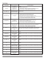
Fault Codes
Fault Codes
No display.
“dr”
Audible alarm also.
“no” “FL”
Audible alarm also.
“no” “AC”
Audible alarm also.
“dc” “LO”
“FL” “- -”
“LI” “oP”
“AC” “rE”
Audible alarm also.
“AC” “HE”
Audible alarm also.
“Sr”
Audible alarm also.
“C1”
“C2”
“C3”
“C4”
“C5”
Fault Code Meaning
DC voltage is
unavailable tothe
refrigerator control
panel or the
refrigerator is OFF.
The door was open for
more than 2 minutes.
The burner did not ignit
or re-ignite.
AC voltage is
unavailable to the
refrigerator control.
DC voltage to the
refrigerator control
panel is too low.
“dc” “LO”
A ame sensed
present when it should
not be.
The high temperature
limit switch is open.
This is a fault within
the refrigerator
controls.
This is a fault within
the refrigerator
controls.
This is a fault within
the refrigerator
controls.
Fresh food air
thermistor sensed out
of range.
Freezer n thermistor
sensed out of range.
Freezer air thermistor
sensed out of range.
Exterior fan thermistor
sensed out of range.
Fresh food n
thermistor sensed out
of range.
Corrective Actions
Check:
- That the refrigerator is ON.
- That the battery charging equipment of the vehicle is operational.
- That the AC/DC converter is operational (if applicable).
- See your dealer or authorized Norcold Service Center.
Close the door.
Check:
- That the valve of the propane gas tank(s) is open.
- That the propane gas is at the correct pressure.
- That the manual shut off valve of the refrigerator is open.
- That there is no air in the propane gas supply line. See “Removing air from
the propane gas supply lines” section of this manual.
- See your dealer or authorized Norcold Service Center.
Check:
- That the refrigerator is plugged into a serviceable outlet.
- That the fuse or circuit breaker is intact.
- That the vehicle generator is operational (if applicble).
- See your dealer or authorized Norcold Service Center.
Check:
- That the battery charging equipment of the vehicle is operational.
- That the AC/DC converter is operational (if applicable).
- See your dealer or authorized Norcold Service Center.
Shut of the propane gas supply to the refrigerator. This is not owner
serviceable. See your dealer or authorized Norcold Service Center.
This is not owner serviceable. See your dealer or authorized Norcold Service
Center.
This is not owner serviceable. See your dealer or authorized Norcold Service
Center.
This is not owner serviceable. See your dealer or authorized Norcold Service
Center.
This is not owner serviceable. See your dealer or authorized Norcold Service
Center.
This is not owner serviceable. See your dealer or authorized Norcold Service
Center.
This is not owner serviceable. See your dealer or authorized Norcold Service
Center.
This is not owner serviceable. See your dealer or authorized Norcold Service
Center.
This is not owner serviceable. See your dealer or authorized Norcold Service
Center.
This is not owner serviceable. See your dealer or authorized Norcold Service
Center.

Owner’s Manual 20
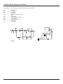
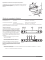
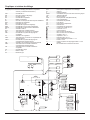
Wiring Diagram and Pictorial
The parts of the wiring diagram and pictorial are (See Art01823
and Art01823-1):
ACH .................... AC Heater
DB....................... Defrost Board
DC ...................... Door Contacts
DH ...................... Divider Heater
dh........................ Divider Housing
DL ....................... Dispenser Light P.C.B.
DPS .................... Dispenser Switch
DS....................... Door Switch
DTH .................... Drip Tray Heater
DWH ................... Dispenser Water Line Heater
DWVH ................. Dispenser Water Valve Heater
EF ....................... External Fan
EFT ..................... External Fan Thermistor
FAT ..................... Freezer Air Thermistor
FDH .................... Freezer Defrost Heater
FF ....................... Freezer Fan
FFAT ................... Fresh Food Air Thermistor
FFDH .................. Fresh Food Defrost heater
FFF ..................... Fresh Food Fan
FFFT ................... Fresh Food Fin Thermistor
FFT ..................... Freezer Fin Thermistor
FH ....................... Flapper Heater
fh......................... Flapper Housing
GV ...................... Gas Valve
HTS .................... Heater Temperature Switch
IG ........................ Igniter
IL ......................... Interior Light
IMWH .................. Ice Maker Water Line Heater
LCD .................... Display Board
MP ...................... Microprocessor
OOS.................... On/Off Switch
PB ....................... Power Board
PH....................... Perimeter Heater
TP ....................... Test Point
TS ....................... Temperature Switch
WV ...................... Water Valve
WVH ................... Water Valve Heater
1.......................... Fused Continuous 12 VDC
2.......................... Switched 12VDC
3.......................... Communications
4.......................... Display Ground
5.......................... Auxillary Ground
6.......................... Auxillary +12VDC
7.......................... Divider +12VDC
8.......................... Gas Valve +12VDC
F1 ....................... (Power Board) 5A DC Fuse
F2 ....................... 8A AC Fuse
F1 ....................... (Defrost Board) 30A DC Fuse
....................... Chassis
........ Wire Foamed In Cabinet
LCD
6
4
DS
2
2
2
FFFT
EFT
FFAT
FFT
FAT
FFF
FF
EF
4
IG
8
30A
5A
F1
DB
PB
2
8
6
6
FFDH
FDH
-12VDC/-12VCC
+12VDC/+12VCC
TS
ACH
ACH
ACH
11
8
2 6
IL
5
FH
dh
DC
DL
WV
IMWH
WVH
DWH
DWVH
DPS
3
HTS
DTH
P2
8A
F2
L1
L2
AC_HT_LO
AC_HT_LO_2
AC_HT_HI
AC_HT_HI_2
LIMIT_OUT
LIMIT_IN
P1
P3
P3
P2
P1
F1
12VDC
GND
GND
GND
12V
12V
GV
TP
fh
DH
PH
TS
TS
Art01823
Page is loading ...
Page is loading ...
Page is loading ...
Page is loading ...
Page is loading ...
Page is loading ...
Page is loading ...
Page is loading ...
Page is loading ...
Page is loading ...
Page is loading ...
Page is loading ...
Page is loading ...
Page is loading ...
Page is loading ...
Page is loading ...
Page is loading ...
Page is loading ...
Page is loading ...
Page is loading ...
Page is loading ...
Page is loading ...
Page is loading ...
Page is loading ...
-
 1
1
-
 2
2
-
 3
3
-
 4
4
-
 5
5
-
 6
6
-
 7
7
-
 8
8
-
 9
9
-
 10
10
-
 11
11
-
 12
12
-
 13
13
-
 14
14
-
 15
15
-
 16
16
-
 17
17
-
 18
18
-
 19
19
-
 20
20
-
 21
21
-
 22
22
-
 23
23
-
 24
24
-
 25
25
-
 26
26
-
 27
27
-
 28
28
-
 29
29
-
 30
30
-
 31
31
-
 32
32
-
 33
33
-
 34
34
-
 35
35
-
 36
36
-
 37
37
-
 38
38
-
 39
39
-
 40
40
-
 41
41
-
 42
42
-
 43
43
-
 44
44


Norcold 2117 Owner's manual
- Type
- Owner's manual
- This manual is also suitable for
Ask a question and I''ll find the answer in the document
Finding information in a document is now easier with AI
in other languages
- français: Norcold 2117 Le manuel du propriétaire
Related papers
-
Norcold 2117 Series Owner's manual
-
-
-
-
-
-
-
-
-