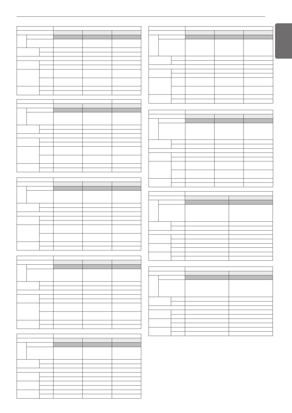
LG ARUN140LLS4 User manual

Type
User manual
P/NO : MFL68165204
INSTALLATION MANUAL
AIR
CONDITIONER
www.lg.com
Please read this installation manual completely before installing the product.
Installation work must be performed in accordance with the national wiring standards by
authorized personnel only.
Please retain this installation manual for future reference after reading it thoroughly.
Original instruction
[Representative] LG Electronics Inc. EU Representative :
LG Electronics European Shared Service Center B.V.
Krijgsman 1, 1186 DM Amstelveen, The Netherlands
[Manufacturer] LG Electronics Inc. Changwon 2nd factory 84, Wanam-ro,
Seongsan-gu, Changwon-si, Gyeongsangnam-do, KOREA
ENGLISH
ITALIANO ESPAÑOL
FRANÇAIS
DEUTSCH
ΕΛΛΗΝΙΚΆ
ČEŠTINA
NEDERLANDS
POLSKI
LIMBA ROMÂNĂ
2
ENGLISH
TIPS FOR SAVING ENERGY
Here are some tips that will help you to minimize the power consump-
tion when you use the air conditioner. You can use your air conditioner
more efficiently by referring to the instructions given below:
IMPORTANT SAFETY INSTRUC-
TIONS
READ ALL INSTRUCTIONS BEFORE
USING THE APPLIANCE.
Always comply with the following precautions
to avoid dangerous situations and ensure peak
performance of your product
WARNING
It can result in serious injury or death when the
directions are ignored
CAUTION
It can result in minor injury or product damage
when the directions are ignored
WARNING
• Installation or repairs made by unqualified
persons can result in hazards to you and oth-
ers.
• The information contained in the manual is
intended for use by a qualified service tech-
nician familiar with safety procedures and
equipped with the proper tools and test in-
struments.
• Failure to carefully read and follow all in-
structions in this manual can result in equip-
ment malfunction, property damage,
personal injury and/or death.
Installation
• Have all electric work done by a licensed
electrician according to "Electric Facility En-
gineering Standard" and "Interior Wire Regu-
lations" and the instructions given in this
manual and always use a special circuit.
- If the power source capacity is inadequate
or electric work is performed improperly,
electric shock or fire may result.
• Ask the dealer or an authorized technician to
install the air conditioner.
- Improper installation by the user may result
in water leakage, electric shock, or fire.
• Always ground the product.
- There is risk of fire or electric shock.
• Always intstall a dedicated circuit and
breaker.
- Improper wiring or installation may cause
fire or electric shock.
• For re-installation of the installed product, al-
ways contact a dealer or an Authorized Serv-
ice Center.
- There is risk of fire, electric shock, explo-
sion, or injury.
• Do not install, remove, or re-install the unit
by yourself (customer).
- There is risk of fire, electric shock, explo-
sion, or injury.
• Do not store or use flammable gas or com-
bustibles near the air conditioner.
- There is risk of fire or failure of product.
!
!
!
• Do not excessively cool indoors. This may be harmful for your
health and may consume more electricity.
• Block sunlight with blinds or curtains while operating the air con-
ditioner.
Keep doors or windows closed tightly while operating the air condi-
tioner.
• Adjust the direction of the air guide vane vertically or horizontally
to circulate indoor air efficiently.
• Speed up the fan to cool or warm indoor air quickly, in a short pe-
riod of time.
• Open windows regularly for ventilation as the indoor air quality
may deteriorate if the air conditioner is used for many hours.
• Clean the air filter once every 2 weeks. Dust and impurities col-
lected in the air filter may block the air flow or weaken the cool-
ing / dehumidifying functions.
For your records
Staple your receipt to this page in case you need it to prove the date
of purchase or for warranty purposes.
Write the model number and the serial number here:
Model number :
Serial number :
Refer the label at side of each unit.
Dealer’s name :
Date of purchase :
3
Use the correctly rated breaker or fuse.
- There is risk of fire or electric shock.
• Prepare for strong wind or earthquake and
install the unit at the specified place.
- Improper installation may cause the unit to
topple and result in injury.
• Do not install the product on a defective in-
stallation stand.
- It may cause injury, accident, or damage to
the product.
• Use a vacuum pump or Inert(nitrogen) gas
when doing leakage test or air purge. Do not
compress air or Oxygen and do not use
Flammable gases. Otherwise, it may cause
fire or explosion.
- There is the risk of death, injury, fire or ex-
plosion.
• When installing and moving the air condi-
tioner to another site, do not charge it with a
different refrigerant from the refrigerant
specified on the unit.
- If a different refrigerant or air is mixed with
the original refrigerant, the refrigerant cycle
may malfunction and the unit may be dam-
aged.
• Do not reconstruct to change the settings of
the protection devices.
- If the pressure switch, thermal switch, or
other protection device is shorted and op-
erated forcibly, or parts other than those
specified by LGE are used, fire or explosion
may result.
• Ventilate before operating air conditioner
when gas leaked out.
- It may cause explosion, fire, and burn.
• Securely install the cover of control box and
the panel.
- If the cover and panel are not installed se-
curely, dust or water may enter the out-
door unit and fire or electric shock may
result.
• If the air conditioner is installed in a small
room, measures must be taken to prevent
the refrigerant concentration from exceed-
ing the safety limit when the refrigerant
leaks.
- Consult the dealer regarding the appropri-
ate measures to prevent the safety limit
from being exceeded. Should the refriger-
ant leak and cause the safety limit to be ex-
ceeded, harzards due to lack of oxygen in
t
he room could result.
• Do not turn on the breaker or power under
condition that front panel, cabinet, top
cover, control box cover are removed or
opened.
- Otherwise, it may cause fire, electric
shook, explosion or death.
Operation
• Do not damage or use an unspecified power
cord.
- There is risk of fire, electric shock, explo-
sion, or injury.
• Use a dedicated outlet for this appliance.
- There is risk of fire or electrical shock.
• Be cautious that water could not enter the
product.
- There is risk of fire, electric shock, or prod-
uct damage.
• Do not touch the power switch with wet
hands.
- There is risk of fire, electric shock, explo-
sion, or injury.
• When the product is soaked (flooded or sub-
merged), contact an Authorized Service Cen-
ter.
- There is risk of fire or electric shock.
• Be cautious not to touch the sharp edges
when installing.
- It may cause injury.
• Take care to ensure that nobody could step
on or fall onto the outdoor unit.
- This could result in personal injury and
product damage.
• Do not open the inlet grille of the product
during operation. (Do not touch the electro-
static filter, if the unit is so equipped.)
- There is risk of physical injury, electric
shock, or product failure.
ENGLISH
4
ENGLISH
CAUTION
Installation
• Always check for gas (refrigerant) leakage
after installation or repair of product.
- Low refrigerant levels may cause failure of
product.
• Do not install the product where the noise
or hot air from the outdoor unit could dam-
age the neighborhoods.
- It may cause a problem for your neighbors.
• Keep level even when installing the product.
- To avoid vibration or water leakage.
• Do not install the unit where combustible
gas may leak.
- If the gas leaks and accumulates around
the unit, an explosion may result.
• Use power cables of sufficient current carry-
ing capacity and rating.
- Cables that are too small may leak, gener-
ate heat, and cause a fire.
• Do not use the product for special purposes,
such as preserving foods, works of art, etc.
It is a consumer air conditioner, not a preci-
sion refrigeration system.
- There is risk of damage or loss of property.
• Keep the unit away from children. The heat
exchanger is very sharp.
- It can cause the injury, such as cutting the
finger. Also the damaged fin may result in
degradation of capacity.
• When installting the unit in a hospital, com-
munication station, or similar place, provide
sufficient protection against noise.
- The inverter equipment, private power gen-
erator, high-frequency medical equipment,
or radio communication equipment may
cause the air conditioner to operate erro-
neously, or fail to operate. On the other
hand, the air conditioner may affect such
equipment by creating noise that disturbs
medical treatment or image broadcasting.
• Do not install the product where it is ex-
posed to sea wind (salt spray) directly.
- It may cause corrosion on the product. Cor-
rosion, particularly on the condenser and
evaporator fins, could cause product mal-
function or inefficient operation.
Operation
• Do not use the air conditioner in special en-
vironments.
- Oil, steam, sulfuric smoke, etc. can signifi-
cantly reduce the performance of the air
conditioner or damage its parts.
• Do not block the inlet or outlet.
- It may cause failure of appliance or acci-
dent.
• Make the connections securely so that the
outside force of the cable may not be ap-
plied to the terminals.
- Inadequate connection and fastening may
generate heat and cause a fire.
• Be sure the installation area does not deteri-
orate with age.
- If the base collapses, the air conditioner
could fall with it, causing property damage,
product failure, or personal injury.
• Install and insulate the drain hose to ensure
that water is drained away properly based
on the installation manual.
- A bad connection may cause water leak-
age.
• Be very careful about product transportation.
- Only one person should not carry the prod-
uct if it weighs more than 20 kg.
- Some products use PP bands for packag-
ing. Do not use any PP bands for a means
of transportation. It is dangerous.
- Do not touch the heat exchanger fins.
Doing so may cut your fingers.
- When transporting the outdoor unit, sus-
pending it at the specified positions on the
unit base. Also support the outdoor unit at
four points so that it cannot slip sideways.
• Safely dispose of the packing materials.
- Packing materials, such as nails and other
metal or wooden parts, may cause stabs or
other injuries.
- Tear apart and throw away plastic packag-
ing bags so that children may not play with
them. If children play with a plastic bag
which was not torn apart, they face the risk
of suffocation.
• Turn on the power at least 6 hours before
starting operation.
- Starting operation immediately after turn-
ing on the main power switch can result in
severe damage to internal parts. Keep the
!
5
ENGLISH
2 TIPS FOR SAVING ENERGY
2 IMPORTANT SAFETY INSTRUCTIONS
6 INSTALLATION PROCESS
6 OUTDOOR UNITS INFORMATION
8 ENVIRONMENT-FRIENDLY ALTERNATIVE
REFRIGERANT R410A
8 SELECT THE BEST LOCATION
9 INSTALLATION SPACE
9 Individual Installation
9 LIFTING METHOD
10 INSTALLATION
10 The location of the Anchor bolts
10 Foundation for Installation
10 Preparation of Piping
12 Plumbing materials and storage methods
12 REFRIGERANT PIPING INSTALLATION
12 Precautions on Pipe connection / Valve operation
13 PIPE CONNECTIONS BETWEEN INDOOR
AND OUTDOOR UNIT
13 Preparation Work
13 Pipe Drawing Out during Single / Series connection
14 Refrigerant piping system
14 Pipe Connection Method between outdoor unit/indoor unit
17 Refrigerant charging
18 Distribution Method
18 Branch pipe Fitting
19 Leak Test and Vacuum drying
20 Vacuum Mode
21 Heat insulation of refrigerant piping
21 ELECTRICAL WIRING
21 Caution
22 Control box and connecting position of wiring
23 Communication and Power Cables
23 Wiring of main power supply and equipment capacity
24 Point for attention regarding quality of the public electric power
supply
25 Field Wiring
27 Checking the setting of outdoor units
27 Automatic Addressing
28 Group Number setting
28 Cool & Heat selector
28 Static pressure compensation mode
28 Night Low Noise Function
29 Overall defrost mode
29 Setting the ODU address
29 Snow removal & rapid defrost
30 Target pressure adjusting
30 High Efficiency cooling mode
30 Auto dust removal mode
31 Smart Load Control
31 Comfort Cooling Function
32 Self-Diagnosis Function
35 CAUTION FOR REFRIGERANT LEAK
35 Introduction
35 Checking procedure of limiting concentration
36 INSTALLATION GUIDE AT THE SEASIDE
36 Model Designation
36 Airborne Noise Emission
TABLE OF CONTENTS
p
ower switch turned on during the opera-
tional season.
• Do not touch any of the refrigerant piping
during and after operation.
- It can cause a burn or frostbite.
• Do not operate the air conditioner with the
panels or guards removed.
- Rotating, hot, or high-voltage parts can
cause injuries.
• Do not directly turn off the main power
switch after stopping operation.
- Wait at least 5 minutes before turning off
the main power switch. Otherwise it may
result in water leakage or other problems.
• Auto-addressing should be done in condition
of connecting the power of all indoor and
outdoour units. Auto-addressing should also
be done in case of changing the indoor unit
PCB.
• Use a firm stool or ladder when cleaning or
maintaining the air conditioner.
- Be careful and avoid personal injury.
• Do not insert hands or other objects through
the air inlet or outlet while the air condi-
tioner is plugged in.
- There are sharp and moving parts that
could cause personal injury.
6
ENGLISH
T
he foundation must be level even
Outdoor unit foundation work
Avoid short circuits and ensure
sufficient space is allowed for service
Installation of outdoor unit
Refer to automatic addressing flowchart
Automatic addressing of indoor unit
In the final check for 24hours at 3.8 MPa(38.7 kgf/cm
2
) there
must be no drop in pressure.
Leak test
Multiple core cable must not be used.
(suitable cable should be selected)
Electrical work
(connection circuits and drive circuits)
M
ake sure no gaps are left where
the insulating materials are joined
Heat insulation work
Make sure airflow is sufficient
Duct work
A
djust to downward gradient
Drain pipe work
S
pecial attention to dryness,
c
leanness and tightness
Refrigerant piping work
C
heck model name to
make sure the fitting
is made correctly
Installation of indoor unit
T
ake account of gradient
o
f drain piping
S
leeve and insert work
M
ake connection clearly between outdoor, indoor,
r
emote controller and option.
Preparation of contract drawings
Indicate clearly who will be responsible for switch setting.
Determination of division work
The vacuum pump used must have a capacity of reaching at least
5 torr, more than 1 hour
Vacuum drying
Recharge correctly as calculated in this manual. and record the
a
mount of added refrigerant
Additional charge of refrigerant
Make sure there are no gaps left between the facing materials
used on the ceiling
Fit facing panels
Run each indoor unit in turn to make sure the pipe work
has been fitted correctly
Test run adjustment
Explain the use of the system as clearly as possible to your customer and
make sure all relevant documentation is in order
Transfer to customer with explanation
P
reheat the crank case with the electrical heater for more than 6 hours.
CAUTION
• The above list indicates the order in which the individual work
operations are normally carried out but this order may be varied
where local conditions warrants such change.
• The thickness of the piping should comply with the relevant local
and national regulations for the designed pressure 3.8 MPa.
• Since R410A is a mixed refrigerant, the required additional refrig-
erant must be charged in its liquid state.(If the refrigerant is
charged in its gaseous state, its composition changes and the
system will not work properly.)
!
C
AUTION
Notes :
1) Rating capacity on heating of Multi V IV Pro is same to rating
capacity on cooling. Please, do refer heating capacity in the
performance table carefully when you design heating capac-
ity by outdoor ambient temperature. All model selection for
capacity is not responsibility of LG.
2) We can guarantee the operation only within 130% combina-
tion ratio. If you want to connect more than 130% combina-
tion ratio, please contact us and discuss the requirement.
3) In case that operating indoor units ratio to rated capacity of
outdoor unit is more than 130%, the airflow should be oper-
ated as low step in the all indoor units.
4) In case of Space Saving Model (ARUN***LLN4), we can rec-
ommend the operation within 120% combination ration for
two or more combination.
5) The numbers in parentheses means maximum connectable
indoor units in accordance with outdoor units combination.
!
Power Supply : 380-415V, 50Hz
Model Name : ARUN***LLS4, ARUN***LLN4
n
Standard Model
CAUTION
* ARUN220LLN4 (Single Unit) model can guarantee the opera-
tion only within 160% combination ratio.
Combination Ratio(50~200%)
!
OUTDOOR UNITS INFORMATION
Number of Outdoor units
Combination Ratio
Standard Model
Space Saving Model
Single Unit
200% 160%*
Two Units Combination
160% 120%
Three or More Units Combination
130% 120%
Unit
1 Outdoor Unit
S
ystem(HP)
Model
C
ombination Unit
I
ndependent Unit
Refrigerant
P
recharged Amount
k
g
lbs
Number of maxmum connectable indoor units
Net Weight
k
g
lbs
Dimensions
(WxHxD)
mm
inch
Piping Conections
mm(inch)
mm(inch)
Unit
1 Outdoor Unit 2 Outdoor Unit
System(HP)
Model
Combination Unit
Independent Unit
Refrigerant
Precharged Amount
kg
lbs
Number of maxmum connectable indoor units
Net Weight
kg
lbs
Dimensions
(WxHxD)
mm
inch
Piping Conections
mm(inch)
mm(inch)
20
ARUN200LLS4
ARUN200LLS4
7.6
16.8
32(50)
259 × 1
571 × 1
(1,240 × 1,680 × 760) × 1
(48-13/16 × 66-5/32
× 29-29/32) x 1
Ø 15.88(5/8)
Ø 28.58(1-1/8)
22
ARUN220LLS4
ARUN120LLS4
ARUN100LLS4
5.0 × 2
11.0 × 2
35(44)
183 × 1 + 178 × 1
403 × 1 + 392 × 1
(920 × 1,680 × 760) × 2
(36-7/32 × 66-5/32 ×
29-29/32) x 2
Ø 15.88(5/8)
Ø 28.58(1-1/8)
24
ARUN240LLS4
ARUN120LLS4
ARUN120LLS4
5.0 × 2
11.0 × 2
39(48)
183 × 2
403 × 2
(920 × 1,680 × 760) × 2
(36-7/32 × 66-5/32 ×
29-29/32) x 2
Ø 15.88(5/8)
Ø 34.9(1-3/8)
Unit
1 Outdoor Unit
System(HP)
Model
Combination Unit
Independent Unit
Refrigerant
Precharged Amount
kg
lbs
Number of maxmum connectable indoor units
Net Weight
kg
lbs
Dimensions
(WxHxD)
mm
inch
Piping Conections
mm(inch)
mm(inch)
14
ARUN140LLS4
ARUN140LLS4
6.6
14.6
23(35)
193 × 1
425 × 1
(920 × 1,680 × 760) × 1
(36-7/32 × 66-5/32
× 29-29/32) × 1
Ø 12.7(1/2)
Ø 28.58(1-1/8)
16
ARUN160LLS4
ARUN160LLS4
6.0
13.2
26(40)
208 × 1
459 × 1
(1,240 × 1,680 × 760) × 1
(48-13/16 × 66-5/32
× 29-29/32) x 1
Ø 12.7(1/2)
Ø 28.58(1-1/8)
18
ARUN180LLS4
ARUN180LLS4
6.0
13.2
29(45)
249 × 1
549 × 1
(1,240 × 1,680 × 760) × 1
(48-13/16 × 66-5/32
× 29-29/32) x 1
Ø 15.88(5/8)
Ø 28.58(1-1/8)
8
ARUN080LLS4
ARUN080LLS4
5
.0
1
1.0
13(20)
178 × 1
3
92 × 1
(
920 × 1,680 × 760) × 1
(36-7/32 × 66-5/32 × 29-29/32) × 1
Ø 9.52(3/8)
Ø 19.05(3/4)
10
ARUN100LLS4
ARUN100LLS4
5
.0
1
1.0
16(25)
178 × 1
3
92 × 1
(
920 × 1,680 × 760) × 1
(36-7/32 × 66-5/32 × 29-29/32) × 1
Ø 9.52(3/8)
Ø 22.2(7/8)
12
ARUN120LLS4
ARUN120LLS4
5
.0
1
1.0
20(30)
183 × 1
4
03 × 1
(
920 × 1,680 × 760) × 1
(36-7/32 × 66-5/32 × 29-29/32) × 1
Ø 12.7(1/2)
Ø 28.58(1-1/8)
Unit
2 Outdoor Unit
System(HP)
Model
Combination Unit
Independent Unit
Refrigerant
Precharged Amount
kg
lbs
Number of maxmum connectable indoor units
Net Weight
kg
lbs
Dimensions
(WxHxD)
mm
inch
Piping Conections
mm(inch)
mm(inch)
26
ARUN260LLS4
ARUN140LLS4
ARUN120LLS4
6.6 × 1 + 5.0 × 1
14.6 × 1 + 11.0 × 1
42(52)
193 × 1 + 183 × 1
425 × 1 + 403 × 1
(920 × 1,680 × 760) × 2
(36-7/32 × 66-5/32 ×
29-29/32) x 2
Ø 19.05(3/4)
Ø 34.9(1-3/8)
28
ARUN280LLS4
ARUN160LLS4
ARUN120LLS4
6.0 × 1 + 5.0 × 1
13.2 × 1 + 11.0 × 1
45(56)
208 × 1 + 183 × 1
459 × 1 + 403 × 1
(1,240 × 1,680 × 760) × 1
+ (920 × 1,680 × 760) × 1
(48-13/16 × 66-5/32 × 29-29/32) x 1
+ (36-7/32×66-5/32×29-29/32)
Ø 19.05(3/4)
Ø 34.9(1-3/8)
30
ARUN300LLS4
ARUN180LLS4
ARUN120LLS4
6.0 × 1 + 5.0 × 1
13.2 × 1 + 11.0 × 1
49(60)
249 × 1 + 183 × 1
549 × 1 + 403 × 1
(1,240 × 1,680 × 760) × 1
+ (920 × 1,680 × 760) × 1
(48-13/16 × 66-5/32 × 29-29/32) x 1
+ (36-7/32×66-5/32×29-29/32)
Ø 19.05(3/4)
Ø 34.9(1-3/8)
INSTALLATION PROCESS
7
ENGLISH
Unit
4 Outdoor Unit
System(HP)
Model
Combination Unit
Independent Unit
Refrigerant
Precharged Amount
kg
lbs
Number of maxmum connectable indoor units
Net Weight
kg
lbs
Dimensions
(WxHxD)
mm
inch
Piping Conections
mm(inch)
mm(inch)
U
nit
2 Outdoor Unit
S
ystem(HP)
M
odel
C
ombination Unit
I
ndependent Unit
R
efrigerant
P
recharged Amount
kg
lbs
N
umber of maxmum connectable indoor units
N
et Weight
k
g
lbs
Dimensions
(
WxHxD)
mm
i
nch
P
iping Conections
m
m(inch)
mm(inch)
32
ARUN320LLS4
ARUN200LLS4
ARUN120LLS4
7.6 × 1 + 5.0 × 1
16.8 × 1 + 11.0 × 1
52(64)
259 × 1 + 183 × 1
571 × 1 + 403 × 1
(1,240 × 1,680 × 760) × 1
+
(920 × 1,680 × 760) × 1
(
48-13/16 × 66-5/32 × 29-29/32) x1
+
(36-7/32×66-5/32×29-29/32)
Ø
19.05(3/4)
Ø
34.9(1-3/8)
34
ARUN340LLS4
ARUN200LLS4
ARUN140LLS4
7.6 × 1 + 6.6 × 1
16.8 × 1 + 14.6 × 1
55(64)
259 × 1 + 193 × 1
571 × 1 + 425 × 1
(1,240 × 1,680 × 760) × 1
+
(920 × 1,680 × 760) × 1
(
48-13/16 × 66-5/32 × 29-29/32) x1
+
(36-7/32×66-5/32×29-29/32)
Ø
19.05(3/4)
Ø
34.9(1-3/8)
36
ARUN360LLS4
ARUN200LLS4
ARUN160LLS4
7.6 × 1 + 6.0 × 1
16.8 × 1 + 13.2 × 1
58(64)
259 × 1 + 208 × 1
571 × 1 + 459 × 1
(
1,240 × 1,680 × 760) × 2
(
4
8-13/16 × 66-5/32 × 29-29/32) x 2
Ø
19.05(3/4)
Ø
41.3(1-5/8)
Unit
2 Outdoor Unit 3 Outdoor Unit
System(HP)
M
odel
C
ombination Unit
I
ndependent Unit
Refrigerant
P
recharged Amount
kg
l
bs
N
umber of maxmum connectable indoor units
Net Weight
kg
lbs
Dimensions
(
WxHxD)
mm
inch
P
iping Conections
mm(inch)
m
m(inch)
38
ARUN380LLS4
ARUN200LLS4
ARUN180LLS4
7
.6 × 1 + 6.0 × 1
16.8 × 1 + 13.2 × 1
61(64)
259 × 1 + 249 × 1
571 × 1 + 549 × 1
(
1,240 × 1,680 × 760) × 2
(
48-13/16 × 66-5/32 × 29-29/32) x 2
Ø 19.05(3/4)
Ø 41.3(1-5/8)
40
ARUN400LLS4
ARUN200LLS4
ARUN200LLS4
7
.6 × 2
16.8 × 2
64
259 × 2
571 × 2
(
1,240 × 1,680 × 760) × 2
(
48-13/16 × 66-5/32 × 29-29/32) x 2
Ø 19.05(3/4)
Ø 41.3(1-5/8)
42
ARUN420LLS4
ARUN180LLS4
ARUN140LLS4
ARUN100LLS4
6
.0 × 1 + 6.6 × 1 + 5.0 × 1
13.2 × 1 + 14.6 × 1 + 11.0 × 1
64
249 × 1 + 193 × 1 + 178 × 1
549 × 1 + 425 × 1 + 392 × 1
(1,240 × 1,680 × 760) × 1
+
(920 × 1,680 × 760) × 2
(
48-13/16 × 66-5/32 × 29-29/32)
x
1
+
(36-7/32 × 66-5/32 × 29-29/32) × 2
Ø 19.05(3/4)
Ø 41.3(1-5/8)
U
nit
3 Outdoor Unit
System(HP)
Model
Combination Unit
Independent Unit
Refrigerant
Precharged Amount
kg
lbs
Number of maxmum connectable indoor units
Net Weight
kg
lbs
Dimensions
(WxHxD)
mm
inch
Piping Conections
mm(inch)
mm(inch)
44
ARUN440LLS4
ARUN200LLS4
ARUN140LLS4
ARUN100LLS4
7.6 × 1 + 6.6 × 1 + 5.0 × 1
16.8 × 1 + 14.6 × 1 + 11.0 × 1
64
259 × 1 + 193 × 1 + 178 × 1
571 × 1 + 425 × 1 + 392 × 1
(1,240 × 1,680 × 760) × 1
+ (920 × 1,680 × 760) × 2
(48-13/16 × 66-5/32 × 29-29/32) x 1
+ (36-7/32 × 66-5/32 × 29-29/32) × 2
Ø 19.05(3/4)
Ø 41.3(1-5/8)
46
ARUN460LLS4
ARUN200LLS4
ARUN160LLS4
ARUN100LLS4
7.6 × 1 + 6.0 × 1 + 5.0 × 1
16.8 × 1 + 13.2 × 1 + 11.0 × 1
64
259 × 1 + 208 × 1 + 178 × 1
571 × 1 + 459 × 1 + 392 × 1
(1,240 × 1,680 × 760) × 2
+ (920 × 1,680 × 760) × 1
(48-13/16 × 66-5/32 × 29-29/32) x 2
+ (36-7/32 × 66-5/32 × 29-29/32) × 1
Ø 19.05(3/4)
Ø 41.3(1-5/8)
48
ARUN480LLS4
ARUN200LLS4
ARUN180LLS4
ARUN100LLS4
7.6 × 1 + 6.0 × 1 + 5.0 × 1
16.8 × 1 + 13.2 × 1 + 11.0 × 1
64
259 × 1 + 249 × 1 + 178 × 1
571 × 1 + 549 × 1 + 392 × 1
(1,240 × 1,680 × 760) × 2
+ (920 × 1,680 × 760) × 1
(48-13/16 × 66-5/32 × 29-29/32) x 2
+ (36-7/32 × 66-5/32 × 29-29/32) × 1
Ø 19.05(3/4)
Ø 41.3(1-5/8)
Unit
3 Outdoor Unit
System(HP)
Model
Combination Unit
Independent Unit
Refrigerant
Precharged Amount
kg
lbs
Number of maxmum connectable indoor units
Net Weight
kg
lbs
Dimensions
(WxHxD)
mm
inch
Piping Conections
mm(inch)
mm(inch)
50
ARUN500LLS4
ARUN200LLS4
ARUN200LLS4
ARUN100LLS4
7.6 × 2 + 5.0 × 1
16.8 × 2 + 11.0 × 1
64
259 × 2 + 178 × 1
571 × 2 + 392 × 1
(1,240 × 1,680 × 760) × 2
+ (920 × 1,680 × 760) × 1
(48-13/16 × 66-5/32 × 29-29/32) x 2
+ (36-7/32 × 66-5/32 × 29-29/32) × 1
Ø 19.05(3/4)
Ø 41.3(1-5/8)
52
ARUN520LLS4
ARUN200LLS4
ARUN200LLS4
ARUN120LLS4
7.6 × 2 + 5.0 × 1
16.8 × 2 + 11.0 × 1
64
259 × 2 + 183 × 1
571 × 2 + 403 × 1
(1,240 × 1,680 × 760) × 2
+ (920 × 1,680 × 760) × 1
(48-13/16 × 66-5/32 × 29-29/32) x 2
+ (36-7/32 × 66-5/32 × 29-29/32) × 1
Ø 19.05(3/4)
Ø 41.3(1-5/8)
54
ARUN540LLS4
ARUN200LLS4
ARUN200LLS4
ARUN140LLS4
7.6 × 2 + 6.6 × 1
16.8 × 2 + 14.6 × 1
64
259 × 2 + 193 × 1
571 × 2 + 425 × 1
(1,240 × 1,680 × 760) × 2
+ (920 × 1,680 × 760) × 1
(48-13/16 × 66-5/32 × 29-29/32) x 2
+ (36-7/32 × 66-5/32 × 29-29/32) × 1
Ø 19.05(3/4)
Ø 41.3(1-5/8)
Unit
3 Outdoor Unit
System(HP)
Model
Combination Unit
Independent Unit
Refrigerant
Precharged Amount
kg
lbs
Number of maxmum connectable indoor units
Net Weight
kg
lbs
Dimensions
(WxHxD)
mm
inch
Piping Conections
mm(inch)
mm(inch)
56
ARUN560LLS4
ARUN200LLS4
ARUN200LLS4
ARUN160LLS4
7.6 × 2 + 6.0 × 1
16.8 × 2 + 13.2 × 1
64
259 × 2 + 208 × 1
571 × 2 + 459 × 1
(1,240 × 1,680 × 760) × 3
(48-13/16 × 66-5/32 × 29-29/32)
Ø 19.05(3/4)
Ø 41.3(1-5/8)
58
ARUN580LLS4
ARUN200LLS4
ARUN200LLS4
ARUN180LLS4
7.6 × 2 + 6.0 × 1
16.8 × 2 + 13.2 × 1
64
259 × 2 + 249 × 1
571 × 2 + 549 × 1
(1,240 × 1,680 × 760) × 3
(48-13/16 × 66-5/32 × 29-29/32) x 3
Ø 19.05(3/4)
Ø 41.3(1-5/8)
60
ARUN600LLS4
ARUN200LLS4
ARUN200LLS4
ARUN200LLS4
7.6 × 3
16.8 × 3
64
259 × 3
571 × 3
(1,240 × 1,680 × 760) × 3
(48-13/16 × 66-5/32 × 29-29/32) x 3
Ø 19.05(3/4)
Ø 41.3(1-5/8)
U
nit
4 Outdoor Unit
System(HP)
M
odel
C
ombination Unit
Independent Unit
Refrigerant
P
recharged Amount
kg
l
bs
N
umber of maxmum connectable indoor units
Net Weight
kg
lbs
D
imensions
(WxHxD)
m
m
i
nch
Piping Conections
mm(inch)
m
m(inch)
62
ARUN620LLS4
ARUN180LLS4
ARUN160LLS4
ARUN140LLS4
ARUN140LLS4
6.0 × 2 + 6.6 × 2
13.2 × 2 + 14.6 × 2
64
249 × 1 + 208 × 1 + 193 × 2
549 × 1 + 459 × 1 + 392 × 2
(
1,240 × 1,680 × 760) × 2
+ (920 × 1,680 × 760) × 2
(
48-13/16 × 66-5/32 × 29-29/32) x 2
+
(36-7/32 × 66-5/32 × 29-29/32) × 2
Ø
22.2(7/8)
Ø
44.5(1-3/4)
64
ARUN640LLS4
ARUN180LLS4
ARUN180LLS4
ARUN140LLS4
ARUN140LLS
4
6.0 × 2 + 6.6 × 2
13.2 × 2 + 14.6 × 2
64
249 × 2 + 193 × 2
549 × 2 + 392 × 2
(
1,240 × 1,680 × 760) × 2
+ (920 × 1,680 × 760) × 2
(
48-13/16 × 66-5/32 × 29-29/32) x 2
+
(36-7/32 × 66-5/32 × 29-29/32) × 2
Ø
22.2(7/8)
Ø
44.5(1-3/4)
66
ARUN660LLS4
ARUN180LLS4
ARUN180LLS4
ARUN160LLS4
ARUN140LLS4
6.0 × 3 + 6.6 × 1
13.2 × 3 + 14.6 × 1
64
249 × 2 + 208 × 1 + 193 × 1
549 × 2 + 459 × 1 + 392 × 1
(
1,240 × 1,680 × 760) × 3
+ (920 × 1,680 × 760) × 1
(
48-13/16 × 66-5/32 × 29-29/32) x 3
+
(36-7/32 × 66-5/32 × 29-29/32) × 1
Ø
22.2(7/8)
Ø
53.98(2-1/8)
Unit
4 Outdoor Unit
System(HP)
M
odel
C
ombination Unit
Independent Unit
Refrigerant
P
recharged Amount
kg
l
bs
N
umber of maxmum connectable indoor units
Net Weight
kg
lbs
Dimensions
(
WxHxD)
mm
inch
Piping Conections
mm(inch)
mm(inch)
68
ARUN680LLS4
ARUN200LLS4
ARUN200LLS4
ARUN140LLS4
ARUN140LLS4
7.6 × 2 + 6.6 × 2
16.8 × 2 + 14.6 × 2
64
259 × 2 + 193 × 2
571 × 2 + 392 × 2
(1,240 × 1,680 × 760) × 2
+ (920 × 1,680 × 760) × 2
(48-13/16 × 66-5/32 × 29-29/32) x 2
+ (36-7/32 × 66-5/32 × 29-29/32) × 2
Ø
22.2(7/8)
Ø 53.98(2-1/8)
70
ARUN700LLS4
ARUN200LLS4
ARUN200LLS4
ARUN160LLS4
ARUN140LLS4
7.6 × 2 + 6.0 × 1 + 6.6 × 1
16.8 × 2 + 13.2 × 1 + 14.6 × 2
64
259 × 2 + 208 × 1 + 193 × 1
571 × 2 + 459 × 1 + 392 × 1
(1,240 × 1,680 × 760) × 3
+ (920 × 1,680 × 760) × 1
(48-13/16 × 66-5/32 × 29-29/32) x 3
+ (36-7/32 × 66-5/32 × 29-29/32) × 1
Ø
22.2(7/8)
Ø 53.98(2-1/8)
72
ARUN720LLS4
ARUN200LLS4
ARUN200LLS4
ARUN180LLS4
ARUN140LLS4
7.6 × 2 + 6.0 × 1 + 6.6 × 1
16.8 × 2 + 13.2 × 1 + 14.6 × 2
64
259 × 2 + 249 × 1 + 193 × 1
571 × 2 + 549 × 1 + 392 × 1
(1,240 × 1,680 × 760) × 3
+ (920 × 1,680 × 760) × 1
(48-13/16 × 66-5/32 × 29-29/32) x 3
+ (36-7/32 × 66-5/32 × 29-29/32) × 1
Ø
22.2(7/8)
Ø 53.98(2-1/8)
74
ARUN740LLS4
ARUN200LLS4
ARUN200LLS4
ARUN180LLS4
ARUN160LLS4
7.6 × 2 + 6.0 × 2
16.8 × 2 + 13.2 × 2
64
259 × 2 + 249 × 1 + 208 × 1
571 × 2 + 549 × 1 + 459 × 1
(1,240×1,680×760) × 4
(48-13/16 × 66-5/32 × 29-29/32) x 4
Ø 22.2(7/8)
Ø 53.98(2-1/8)
76
ARUN760LLS4
ARUN200LLS4
ARUN200LLS4
ARUN180LLS4
ARUN180LLS4
7.6 × 2 + 6.0 × 2
16.8 × 2 + 13.2 × 2
64
259 × 2 + 249 × 2
571 × 2 + 549 × 2
(1,240×1,680×760) × 4
(48-13/16 × 66-5/32 × 29-29/32) x 4
Ø 22.2(7/8)
Ø 53.98(2-1/8)
Unit
4 Outdoor Unit
System(HP)
Model
Combination Unit
Independent Unit
Refrigerant
Precharged Amount
kg
lbs
Number of maxmum connectable indoor units
Net Weight
kg
lbs
Dimensions
(WxHxD)
mm
inch
Piping Conections
mm(inch)
mm(inch)
78
ARUN780LLS4
ARUN200LLS4
ARUN200LLS4
ARUN200LLS4
ARUN180LLS4
7.6 × 3 + 6.0 × 1
16.8 × 3 + 13.2 × 1
64
259 × 3 + 249 × 1
571 × 3 + 549 × 1
(1,240 × 1,680 × 760) × 4
(48-13/16 × 66-5/32 × 29-29/32) x 4
Ø 22.2(7/8)
Ø 53.98(2-1/8)
80
ARUN800LLS4
ARUN200LLS4
ARUN200LLS4
ARUN200LLS4
ARUN200LLS4
7.6 × 4
16.8 × 4
64
259 × 4
571 × 4
(1,240 × 1,680 × 760) × 4
(48-13/16 × 66-5/32 × 29-29/32) x 4
Ø 22.2(7/8)
Ø 53.98(2-1/8)
8
ENGLISH
ENVIRONMENT-FRIENDLY ALTER-
NATIVE REFRIGERANT R410A
The refrigerant R410A has the property of higher operating pressure in
comparison with R22.
Therefore, all materials have the characteristics of higher resisting
pressure than R22 ones and this characteristic should be also consid-
ered during the installation.
R410A is an azeotrope of R32 and R125 mixed at 50:50, so the ozone
depletion potential (ODP) of R410A is 0. These days the developed
countries have approved it as the environment-friendly refrigerant and
encouraged to use it widely to prevent environment pollution.
SELECT THE BEST LOCATION
Select space for installing outdoor unit, which will meet the following
conditions:
• No direct thermal radiation from other heat sources
• No possibility of annoying neighbors by noise from unit
• No exposition to strong wind
• With strength which bears weight of unit
• Note that drain flows out of unit when heating
• With space for air passage and service work shown next
• Because of the possibility of fire, do not install unit to the space
where generation, inflow, stagnation, and leakage of combustible
gas is expected.
• Avoid unit installation in a place where acidic solution and spray (sul-
fur) are often used.
• Do not use unit under any special environment where oil, steam and
sulfuric gas exist.
• It is recommended to fence round the outdoor unit in order to pre-
vent any person or animal from accessing the outdoor unit.
• If installation site is area of heavy snowfall, then the following direc-
tions should be observed.
- Make the foundation as high as possible.
- Fit a snow protection hood.
Select installation location considering following conditions to avoid
bad condition when additionally performing defrost operation.
- Install the outdoor unit at a place well ventilated and having a lot of
sunshine in case of installing the product at a place With a high hu-
midity in winter (near beach, coast, lake, etc.)
(Ex : Rooftop where there is always sunshine.)
CAUTION
• The wall thickness of the piping should comply with the relevant
local and national regulations for the designed pressure 3.8 MPa
• Since R410A is a mixed refrigerant, the required additional re-
frigerant must be charged in its liquid state.
If the refrigerant is charged in its gaseous state, its composition
changes and the system will not work properly.
• Do not place the refrigerant container under the direct rays of
the sun to prevent it from exploding.
• For high-pressure refrigerant, any unapproved pipe must not be
used.
• Do not heat pipes more than necessary to prevent them from
softening.
• Be careful not to install wrongly to minimize economic loss be-
cause it is expensive in comparison with R22.
!
n
Space Saving Model
U
nit
4 Outdoor Unit
S
ystem(HP)
Model
C
ombination Unit
Independent Unit
Refrigerant
Precharged Amount
kg
lbs
Number of maxmum connectable indoor units
Net Weight
kg
lbs
Dimensions
(WxHxD)
mm
inch
Piping Conections
mm(inch)
mm(inch)
U
nit
2 Outdoor Unit
S
ystem(HP)
Model
Combination Unit
Independent Unit
R
efrigerant
Precharged Amount
k
g
l
bs
Number of maxmum connectable indoor units
N
et Weight
k
g
l
bs
D
imensions
(WxHxD)
m
m
inch
P
iping Conections
mm(inch)
m
m(inch)
22
ARUN220LLN4
ARUN220LLN4
7
.6
1
6.8
3
5(44)
2
59 × 1
5
71 × 1
(
1,240 × 1,680 × 760) × 1
(
48-13/16 × 66-5/32
×
29-29/32) x 1
Ø
15.88(5/8)
Ø 28.58(1-1/8)
42
ARUN420LLN4
ARUN220LLN4
ARUN200LLS4
7
.6 × 2
1
6.8 × 2
6
4
2
59 × 2
5
71 × 2
(
1,240 × 1,680 × 760) × 2
(
48-13/16 × 66-5/32
×
29-29/32) x 2
Ø
19.05(3/4)
Ø 41.3(1-5/8)
44
ARUN440LLN4
ARUN220LLN4
ARUN220LLN4
7
.6 × 2
1
6.8 × 2
6
4
2
59 × 2
5
71 × 2
(
1,240 × 1,680 × 760) × 2
(
48-13/16 × 66-5/32
×
29-29/32) x 2
Ø
19.05(3/4)
Ø 41.3(1-5/8)
Unit
3 Outdoor Unit
System(HP)
Model
C
ombination Unit
Independent Unit
Refrigerant
P
recharged Amount
kg
l
bs
N
umber of maxmum connectable indoor units
Net Weight
kg
lbs
Dimensions
(WxHxD)
m
m
i
nch
Piping Conections
mm(inch)
mm(inch)
62
ARUN620LLN4
ARUN220LLN4
ARUN200LLS4
ARUN200LLS4
7
.6 x 3
16.8 x 3
64
259 × 3
571 × 3
(1,240 × 1,680 × 760) × 3
48-13/16 × 66-5/32
× 29-29/32) x 3
Ø 22.2(7/8)
Ø
44.5(1-3/4)
64
ARUN640LLN4
ARUN220LLN4
ARUN220LLN4
ARUN200LLS4
7
.6 x 3
16.8 x 3
64
259 × 3
571 × 3
(1,240 × 1,680 × 760) × 3
48-13/16 × 66-5/32
× 29-29/32) x 3
Ø 22.2(7/8)
Ø
44.5(1-3/4)
66
ARUN660LLN4
ARUN220LLN4
ARUN220LLN4
ARUN200LLS4
7
.6 x 3
16.8 x 3
64
259 × 3
571 × 3
(1,240 × 1,680 × 760) × 3
48-13/16 × 66-5/32
× 29-29/32) x 3
Ø 22.2(7/8)
Ø
53.98(2-1/8)
82
ARUN820LLN4
ARUN220LLN4
ARUN200LLS4
ARUN200LLS4
ARUN200LLS4
7.6 x 4
16.8 x 4
64
259 × 4
571 × 4
(1,240 × 1,680 × 760) × 4
(48-13/16 × 66-5/32
× 29-29/32) x 4
Ø 22.2(7/8)
Ø 53.98(2-1/8)
84
ARUN840LLN4
ARUN220LLN4
ARUN220LLN4
ARUN200LLS4
ARUN200LLS4
7.6 x 4
16.8 x 4
64
259 × 4
571 × 4
(1,240 × 1,680 × 760) × 4
(48-13/16 × 66-5/32
× 29-29/32) x 4
Ø 22.2(7/8)
Ø 53.98(2-1/8)
Unit
4 Outdoor Unit
System(HP)
Model
Combination Unit
Independent Unit
Refrigerant
Precharged Amount
kg
lbs
Number of maxmum connectable indoor units
Net Weight
kg
lbs
Dimensions
(WxHxD)
mm
inch
Piping Conections
mm(inch)
mm(inch)
86
ARUN860LLN4
ARUN220LLN4
ARUN220LLN4
ARUN220LLN4
ARUN200LLS4
7.6 x 4
16.8 x 4
64
259 × 4
571 × 4
(1,240 × 1,680 × 760) × 4
(48-13/16 × 66-5/32
× 29-29/32) x 4
Ø 22.2(7/8)
Ø 53.98(2-1/8)
88
ARUN880LLN4
ARUN220LLN4
ARUN220LLN4
ARUN220LLN4
ARUN220LLN4
7.6 x 4
16.8 x 4
64
259 × 4
571 × 4
(1,240 × 1,680 × 760) × 4
(48-13/16 × 66-5/32
× 29-29/32) x 4
Ø 22.2(7/8)
Ø 53.98(2-1/8)
9
ENGLISH
During the installation of the unit, consider service, inlet, and outlet and
acquire the minimum space as shown in the figures below.
Seasonal wind and cautions in winter
• Sufficient measures are required in a snow area or severe cold area
in winter so that product can be operated well.
• Get ready for seasonal wind or snow in winter even in other areas.
• Install a suction and discharge duct not to let in snow or rain.
• Install the outdoor unit not to come in contact with snow directly. If
snow piles up and freezes on the air suction hole, the system may
malfunction. If it is installed at snowy area, attach the hood to the
system.
• Install the outdoor unit at the higher installation console by 50 cm
than the average snowfall (annual average snowfall) if it is installed at
the area with much snowfall.
• Where snow accumulated on the upper part of the Outdoor Unit by
more than 10 cm, always remove snow for operation.
- The height of H frame must be more than 2 times the snowfall
and its width shall not exceed the width of the product. (If width
of the frame is wider than that of the product, snow may accu-
mulate)
- Don't install the suction hole and discharge hole of the Outdoor
Unit facing the seasonal wind.
CAUTION
Be very careful while carrying the product.
Do not have only one person carry product if it is more than 20 kg.
• PP bands are used to pack some products. Do not use them as
a mean for transportation because they are dangerous.
• Do not touch heat exchanger fins with your bare hands. Other-
wise you may get a cut in your hands.
• Tear plastic packaging bag and scrap it so that children cannot
play with it. Otherwise plastic packaging bag may suffocate chil-
dren to death.
• When carrying in Outdoor Unit, be sure to support it at four
points. Carrying in and lifting with 3-point support may make
Outdoor Unit unstable, resulting in a fall.
• Use 2 belts of at least 8 m long.
• Place extra cloth or boards in the locations where the casing
comes in contact with the sling to prevent damage.
Hoist the unit making sure it is being lifted at its center of gravity.
Locking points for
transportation ropes
Forklift Carrying Guide
Forklift Carrying Hole
!
Category
Installation Space
Case 1
(10mmSide Space49mm)
Case 2
(Side Space49mm)
4 sides
are
walls
A10
B300
C10
D500
A50
B100
C50
D500
A10
B300
C10
D500
E20
A50
B100
C50
D500
E100
A10
B300
C10
D500
E20
F600
A50
B100
C50
D500
E100
F500
A10
B300
C10
D300
E20
F500
A50
B100
C50
D100
E100
F500
Rear
to
Rear
A10
B500
C10
D500
E20
F900
A50
B500
C50
D500
E100
F600
A10
B500
C10
D500
E20
F1200
A50
B500
C50
D500
E100
F900
A10
B500
C10
D500
E20
F1800
A50
B500
C50
D500
E100
F1200
Only 2
sides
are
walls
A10
B300
A200
B300
E400
Limita-
tions on
the
height
of the
wall
(Refer
to 4 side
walls)
AE
B
D
AA
CC
BB
DD Front
Front
E
C
AE
B
F
C
D
AE
B
F
C
D
A
E
B
A
B
E
h2
h1
1500
A
B
500
Front
Front
Front
Front
No limit to the height of the wall
Front
No limit to the height of the wall
AE
B
F
C
D
AE
B
F
C
D
E
A
B
F
C
D
Front
Front
Front
Front
Front
Front
AA EE
BB
DD
A
C
B
D Front
Front
EE
CC
AE
B
F
C
D
AE
B
F
C
D
A
E
B
A
B
E
h2
h1
1500
A
B
500
Front
Front
Front
Front
No limit to the height of the wall
Front
No limit to the height of the wall
AE
B
F
C
D
AE
B
F
C
D
E
A
B
F
C
D
Front
Front
Front
Front
Front
Front
AE
B
D
A
C
B
D Front
Front
E
C
AA EE
BB
FF
CC
DD
AE
B
F
C
D
A
E
B
A
B
E
h2
h1
1500
A
B
500
Front
Front
Front
Front
No limit to the height of the wall
Front
No limit to the height of the wall
AE
B
F
C
D
AE
B
F
C
D
E
A
B
F
C
D
Front
Front
Front
Front
Front
Front
AE
B
D
A
C
B
D Front
F
ront
E
C
A
E
B
F
C
D
AA EE
BB
FF
CC
DD
A
E
B
A
B
E
h2
h1
1500
A
B
500
Front
Front
Front
Front
No limit to the height of the wall
Front
No limit to the height of the wall
AE
B
F
C
D
AE
B
F
C
D
E
A
B
F
C
D
Front
F
ront
Front
Front
Front
Front
AE
B
D
A
C
B
D
Front
Front
E
C
AE
B
F
C
D
AE
B
F
C
D
A
E
B
A
B
E
h2
h1
1500
A
B
500
Front
Front
Front
Front
No limit to the height of the wall
Front
No limit to the height of the wall
AE
B
F
C
D
AE
B
F
C
D
E
AA
BB
FF
C
C
D
D
Front
Front
Front
Front
Front
F
ront
AE
B
D
A
C
B
D Front
Front
E
C
A
E
B
F
C
D
AE
B
F
C
D
A
E
B
A
B
E
h2
h1
1500
A
B
500
Front
Front
Front
Front
No limit to the height of the wall
Front
No limit to the height of the wall
AA EE
BB
F
F
CC
D
D
AE
B
F
C
D
E
A
B
F
C
D
F
ront
Front
Front
Front
Front
Front
AE
B
D
A
C
B
D Front
Front
E
C
AE
B
F
C
D
AE
B
F
C
D
A
E
B
A
B
E
h2
h1
1500
A
B
500
Front
Front
F
ront
Front
No limit to the height of the wall
Front
No limit to the height of the wall
AE
B
F
C
D
AA EE
BB
FF
CC
DD
EE
A
B
F
C
D
Front
Front
Front
Front
Front
Front
AE
B
D
A
C
B
D Front
Front
E
C
A
E
B
F
C
D
A
E
B
F
C
D
A
E
B
AA
BB
E
h2
h1
1500
A
B
500
Front
F
ront
Front
Front
No limit to the height of the wall
Front
No limit to the height of the wall
AE
B
F
C
D
AE
B
F
C
D
E
A
B
F
C
D
Front
Front
Front
Front
Front
Front
AE
B
D
A
C
B
D Front
Front
E
C
A
E
B
F
C
D
AE
B
F
C
D
AA
EE
BB
A
B
EE
h2
h1
1500
A
B
500
Front
Front
Front
Front
No limit to the height of the wall
Front
No limit to the height of the wall
AE
B
F
C
D
AE
B
F
C
D
E
A
B
F
C
D
F
ront
Front
Front
Front
Front
Front
h2
h1
1500
A
B
500
240 or
more
50 or more
45° or
more
240 or
more
50 or more
45° or
more
1412
5202
h2
h1
1500
A
B
500
• The height of the wall on the front side
must be 1500mm or less.
• The height of the wall on the inlet side
must be 500mm or less.
• There is no limit to the wall on the side.
• If the height of the walls on the front and
the side are higher than the limit, there
must be additional space on the front and
the side.
- Additional Space on the front side by
1/2 of h1.
- Additional Space on the inlet side by
1/2 of h2
- h1 = A(Actual height) - 1500
- h2 = B(Actual height) - 500
LIFTING METHOD
• When carrying the suspended, unit pass the ropes under the unit and
use the two suspension points each at the front and rear.
• Always lift the unit with ropes attached at four points so that impact
is not applied to the unit.
• Attach the ropes to the unit at an angle of 40° or less.
Individual Installation
INSTALLATION SPACE
10
ENGLISH
• Install at places where it can endure the weight and vibration/noise
of the outdoor unit.
• The outdoor unit supports at the bottom shall have width of at least
100 mm under the Unit’s legs before being fixed.
• The outdoor unit supports should have minimum height of 200 mm.
• Anchor bolts must be inserted at least 75 mm.
A
t
l
e
a
s
t
1
0
0
m
m
A
t
l
e
a
s
t
1
0
0
m
m
A
t
l
e
a
s
t
1
0
0
m
m
A
t
l
e
a
s
t
1
0
0
m
m
A
t
l
e
a
s
t
1
0
0
m
m
A
t
l
e
a
s
t
1
0
0
m
m
Center of the Unit
F
or outdoor units
s
hould not be
s
upported only by the
c
orner supports.
Center of the Unit
730
760
6565
Unit : mm
At least 65At least 65
Chassis Outdoor Unit Capacity A(mm) B(mm)
UX5 8~14 HP 920 792
UX6 16~22 HP 1240 1102
• Fix the unit tightly with bolts as shown below so that unit will not fall
down due to earthquake or gust.
• Use the H-beam support as a base support
• Noise and vibration may occur from the floor or wall since vibration is
transferred through the installation part depending on installation sta-
tus. Thus, use anti-vibration materials (cushion pad) fully (The base
pad shall be more than 200 mm).
At least 200 mm
Unit : mm
200
75
75
200
100
At least 200 mm
U
nit : mm
200
75
75
200
100
The corner part must be fixed firmly. Otherwise, the support for the
installation may be bent.
Get and use M10 Anchor bolt.
Put Cushion Pad between the outdoor unit and ground support for
the vibration protection in wide area.
Space for pipes and wiring
(Pipes and wirings for bottom side)
H-beam support
Concrete support
CAUTION
• Be sure to remove the Pallet(Wood Support) of the bottom
side of the outdoor unit Base Pan before fixing the bolt. It
may cause the unstable state of the outdoor settlement,
and may cause freezing of the heat exchanger resulting in
abnormal operations.
• Be sure to remove the Pallet(Wood Support) of the bottom
side of the outdoor unit before welding. Not removing Pal-
let(Wood Support) causes hazard of fire during welding.
WARNING
• Install where it can sufficiently support the weight of the out-
door unit.
If the support strength is not enough, the outdoor unit may drop
and hurt people.
• Install where the outdoor unit may not fall in strong wind or
earthquake.
If there is a fault in the supporting conditions, the outdoor unit
may fall and hurt people.
• Please take extra cautions on the supporting strength of the
ground, water outlet treatment(treatment of the water flowing
out of the outdoor unit in operation), and the passages of the
pipe and wiring, when making the ground support.
• Do not use tube or pipe for water outlet in the Base pan. Use
drainage instead for water outlet. The tube or pipe may freeze
and the water may not be drained.
Pallet(Wood Support)
- Remove before Installation
!
!
Main cause of gas leakage is defect in flaring work. Carry out correct
flaring work in the following procedure.
Cut the pipes and the cable
- Use the accessory piping kit or the pipes purchased locally.
- Measure the distance between the indoor and the outdoor unit.
- Cut the pipes a little longer than measured distance.
- Cut the cable 1.5m longer than the pipe length.
Copper
tube
90°
Slanted Uneven Rough
Pipe
Reamer
Point down
Flare nut
Copper tube
Bar
Copper pipe
Clamp handle
Red arrow mark
Cone
Yoke
Handle
Bar
"A"
Inclined
Inside is shining without scratches.
Smooth all round
Even length
all round
Surface
damaged
Cracked Uneven
thickness
= Improper flaring =
Copper
tube
90°
Slanted Uneven Rough
Pipe
Reamer
Point down
Flare nut
Copper tube
Bar
Copper pipe
Clamp handle
Red arrow mark
Cone
Yoke
Handle
Bar
"A"
Inclined
Inside is shining without scratches.
Smooth all round
Even length
all round
Surface
damaged
Cracked Uneven
thickness
= Improper flaring =
Preparation of Piping
Foundation for Installation
The location of the Anchor bolts
INSTALLATION
11
Burrs removal
- Completely remove all burrs from the cut cross section of pipe/tube.
- Put the end of the copper tube/pipe to downward direction as you re-
move burrs in order to avoid to let burrs drop in the tubing.
Flaring work
- Carry out flaring work using flaring tool as shown below.
Firmly hold copper tube in a bar(or die) as indicated dimension in the
table above.
Check
- Compare the flared work with figure below.
- If flare is noted to be defective, cut off the flared section and do flar-
ing work again.
ENGLISH
Indoor unit
[kW(Btu/h]
Pipe " A "
Gas Liquid Gas Liquid
<5.6(19,100) 1/2" 1/4" 0.5~0.8 0~0.5
<16.0(54,600) 5/8" 3/8" 0.8~1.0 0.5~0.8
<22.4(76,400) 3/4" 3/8" 1.0~1.3 0.5~0.8
C
opper
tube
90°
Slanted Uneven Rough
Pipe
R
eamer
Point down
F
lare nut
C
opper tube
Bar
C
opper pipe
Clamp handle
R
ed arrow mark
Cone
Y
oke
H
andle
B
ar
"
A"
Inclined
Inside is shining without scratches.
S
mooth all round
Even length
all round
Surface
damaged
Cracked Uneven
thickness
= Improper flaring =
C
opper
t
ube
9
S
lanted Uneven Rough
P
ipe
R
eamer
Point down
F
lare nut
C
opper tube
Bar
C
opper pipe
Clamp handle
R
ed arrow mark
Cone
Y
oke
H
andle
B
ar
"
A"
Inclined
Inside is shining without scratches.
S
mooth all round
Even length
all round
Surface
damaged
Cracked Uneven
thickness
= Improper flaring =
Flare shape and flare nut tightening torque
Opening shutoff valve
Precautions when connecting pipes
- See the following table for flare part machining dimensions.
- When connecting the flare nuts, apply refrigerant oil to the inside and
outside of the flares and turn them three or four times at first. (Use
ester oil or ether oil.)
-
See the following table for tightening torque.(Applying too much torque may
cause the flares to crack.)
- After all the piping has been connected, use nitrogen to perform a
gas leak check.
1 Remove the cap and turn the valve counter clockwise with the
hexagon wrench.
2 Turn it until the shaft stops.
Do not apply excessive force to the shutoff valve. Doing so may
break the valve body, as the valve is not a backseat type. Always
use the special tool.
3 Make sure to tighten the cap securely.
Pipe size
Tightening
torque(N·m)
A(mm) Flare shape
Ø9.52 38±4 12.8-13.2
90°
±2
4
5
°
±
2
A
R=0.4~0.8
Ø12.7 55±6 16.2-16.6
Ø15.88 75±7 19.3-19.7
CAUTION
• Always use a charge hose for service port connection.
After tightening the cap, check that no refrigerant leaks are present
.
• When loosening a flare nut, always use two wrenches in
combination, When connecting the piping,
always use a spanner and torque wrench
in combination to tighten the flare nut.
• When connecting a flare nut, coat the
flare(inner and outer faces) with oil for
R410A(PVE) and hand tighten the nut
3 to 4 turns as the initial tightening.
Outdoor
uni t
Liquid side
Flare connection
Flare connection
Gas side
Indoor
unit
Union
!
Insulation of shutoff valve
1 Use the heat insulation material for the refrigerant piping which has
an excellent heat-resistance (over 120 °C).
2 Precautions in high humidity circumstance:
This air conditioner has been tested according to the "ISO Condi-
tions with Mist" and confirmed that there is not any default. How-
ever, if it is operated for a long time in high humid atmosphere
(dew point temperature: more than 23 °C), water drops are liable to
fall. In this case, add heat insulation material according to the fol-
lowing procedure:
- Heat insulation material to be prepared... EPDM (Ethylene Propy-
lene Diene Methylene)-over 120 °C the heat-resistance tempera-
ture.
- Add the insulation over 10 mm thickness at high humidity environ-
ment.
Indoor unit
Thermal insulator
(accessory)
Fastening band
(accessory)
Refrigerant piping
Closing shutoff valve
1 Remove the cap and turn the valve clockwise with the hexagon
wrench.
2 Securely tighten the valve until the shaft contacts the main body seal.
3 Make sure to tighten the cap securely.
* For the tightening torque, refer to the table on the below.
Tightening torque
Shutoff
valve
size
Tightening torque N·m(Turn clockwise to close)
Shaft(valve body)
Cap(Valve
lid)
Service
port
Flare
nut
Gas line piping at-
tached to unit
Ø 6.35
6 ± 0.6
Hexagonal
wrench 4
mm
29.4 ± 2.9
12.7±2
16 ± 2
-
Ø 9.52 38 ± 4
Ø 12.7
9 ± 0.9
53.9 ± 5.8
55 ± 6
Ø 15.88
15 ± 1.5
Hexagonal
wrench 6
mm
75 ± 7
Ø 22.2
30 ± 3
Hexagonal
wrench 10
mm
- 25 ± 3
Ø 25.4
12
ENGLISH
Refrigerant piping on three principles
Drying Cleanliness Airtight
Should be no moisture
inside
No dust inside.
There is no refrigerant
leakage
Items
Moisture Dust
Leakage
Moisture
Dust
Leakage
Moisture Dust
L
eakage
Cause
failure
- Significant hydroly-
sis of refrigerant oil
- Degradation of re-
frigerant oil
- Poor insulation of
the compressor
- Do not cold and
warm
- Clogging of EEV,
Capillary
- Degradation of re-
frigerant oil
- Poor insulation of
the compressor
- Do not cold and
warm
- Clogging of EEV,
Capillary
- Gas shortages
- Degradation of re-
frigerant oil
- Poor insulation of
the compressor
- Do not cold and
warm
Coun-
termea-
sure
-
No moisture in the pipe
- Until the connec-
tion is completed,
the plumbing pipe
entrance should be
strictly controlled.
- Stop plumbing at
rainy day.
- Pipe entrance
should be taken
side or bottom.
-
When removal burr
after cutting pipe,
pipe entrance should
be taken down.
- Pipe entrance
should be fitted
cap when pass
through the walls.
-
No dust in the pipe.
- Until the connec-
tion is completed,
the plumbing pipe
entrance should be
strictly controlled.
- Pipe entrance
should be taken
side or bottom.
- When removal
burr after cutting
pipe, pipe entrance
should be taken
down.
- Pipe entrance
should be fitted
cap when pass
through the walls.
- Airtightness test
should be.
- Brazing operations
to comply with
standards.
- Flare to comply
with standards.
- Flange connec-
tions to comply
with standards.
Nitrogen substitution method
Welding, as when heating without nitrogen substitution a large
amount of the oxide film is formed on the internal piping.
The oxide film is a caused by clogging EEV, Capillary, oil hole of accu-
mulator and suction hole of oil pump in compressor.
It prevents normal operation of the compressor.
In order to avoid this problem, Welding should be done after replacing
air by nitrogen gas.
When welding plumbing pipe, the work is required.
1 Always use the nitrogen.(not use oxygen, carbon dioxide, and
a Chevron gas): Please use the following nitrogen pressure
0.02 MPa Oxygen – Promotes oxidative degradation of refrig-
erant oil.
Because it is flammable, it is strictly prohibited to use Carbon
dioxide – Degrade the drying characteristics of gas Chevron
Gas – Toxic gas occurs when exposed to direct flame.
2 Always use a pressure reducing valve.
3
Please do not use commercially available antioxidant.
The residual material seems to be the oxide scale is observed.
In fact, due to the organic acids generated by oxidation of the
alcohol contained in the anti-oxidants, ants nest corrosion oc-
curs. (causes of organic acid alcohol + copper + water +
temperature)
CAUTION
!
Regulator
Nitrogen gas Nitrogen gas
Pressure 0.02 MPa less Pressure 0.02 MPa less
Nitrogen gas
Pressure 0.02 MPa less
Auxiliary valve
Taping
(Should not
contain air)
Welding Point
Note) should not block the outlet side.
When the internal pressure in pipe is abo
ve the atmospheric pressure, pinhole is o
ccurred and it is a leakage cause.
Oxide scale
Nitrogen
CAUTION
Please block the pipe knock outs of the front and side panels after
installing the pipes.
(Animals or foreign objects may be brought in to damage wires.)
!
WARNING
• Always careful not to leak the refrigerant during welding.
• The refrigerant generates poisonous gas harmful to human body
if combusted.
• Do not perform welding in a closed space.
• Be sure to close the cap of the service port to prevent gas leak-
age after the work.
!
Gas pipe
Liquid pipe
Refrigerant
Charging Port
Service Port
REFRIGERANT PIPING INSTALLATION
Precautions on Pipe connection / Valve operation
Pipe connection is done by connecting from the end of the pipe to the
branching pipes, and the refrigerant pipe coming out of the outdoor
unit is divided at the end to connect to each indoor unit. Flare connec-
tion for the indoor unit, and welding connection for the outdoor pipe
and the branching parts.
- Use hexagonal wrench to open/close the valve.
P
lumbing materials and storage methods
Pipe must be able to obtain the specified thickness and should be
used with low impurities.
Also when handling storage, pipe must be careful to prevent a frac-
ture, deformity and wound.
Should not be mixed with contaminations such as dust, moisture.
13
ENGLISH
- Pipe connections can be done on the front side or on the side accord-
ing to the installation environments.
- Be sure to let 0.2kgf/cm
2
Nitrogen flow in the pipe when welding.
- If Nitrogen was not flown during welding, many oxidized membranes
may form inside the pipe and disturb the normal operations of valves
and condensers.
CAUTION
• Do not give damage to the pipe/base during the Knock Out
work.
• Proceed to pipe work after removing burr after Knock Out work.
• Perform sleeve work to prevent damage to the wire when con-
necting wires using knock Outs.
!
Remove leakage prevention cap
• Remove the leakage prevention cap attached to the outdoor unit
service valve before pipe work.
• Proceed the leakage prevention cap removal as follows:
- Verify whether the liquid/gas pipes are locked.
- Extract remaining refrigerant or air inside using the service port.
- Remove the leakage prevention cap
Method of drawing out pipes on the bottom side
- Drawing out common pipe through side panel
Left Side Pipe
Draw Out
Front Pipe Draw Out
Right Side Pipe
Draw Out
R
efrigerant Pipe
R
egulator
N
itrogen
Taping
V
alve
NitrogenNitrogen
D
irection Direction
Nitrogen
D
irection
Removal Area for Liquid/Gas pipe
bottom side connections.
Gas pipe
Liquid pipe
Service Port
Refrigerant Charging Port
Leakage Prevention Cap
Pipe Knock Out for
Liquid/Gas pipes
Liquid pipe Gas pipe
Remove only liquid/gas pipe Knock out
Liquid pipe Gas pipe
Remove only liquid/gas pipe Knock out
P
ipe Drawing Out during Single / Series connection
Method of drawing out pipes on the front side
- Proceed with the pipe work as shown in the below figure for front
side pipe drawing out.
Preparation Work
- Use Knock Outs of Base Pan of the outdoor unit for Left/Right or Bot-
tom pipe drawing outs.
PIPE CONNECTIONS BETWEEN
INDOOR AND OUTDOOR UNIT
14
ENGLISH
Y branch method
Combination of Y
branch/header Method
Header Method
:
Outdoor Unit
: 1st branch (Y branch)
: Indoor Units
: Outdoor Unit
: 1st branch (Y branch)
: Y branch
: Indoor Unit
: Header
: Sealed piping
: Outdoor Unit
: Header branch
: Indoor Units
: Sealed piping
: Outdoor Unit
: 1st branch (Y branch)
: Indoor Units
: Downward Indoor Unit
: Connection branch
pipe between
Outdoor units:
ARCNN31
: Connection branch
pipe between
Outdoor units:
ARCNN21
l
40 m (90 m : Conditional application)
h 30 m
H 90 m
L165 m
L 165 m
40 m(90 m : Conditional application)
H 90 m
30 m
L 165 m
40 m
H 90 m
30 m
1 Outdoor Units
Y branch method
Combination of Y branch/
header Method
H
eader Method
: Outdoor Unit
: Header branch
: Indoor Units
: Sealing
: Connection branch pipe
between Outdoor
units : ARCNN41
: Connection branch pipe
between Outdoor
units : ARCNN31
: Connection branch pipe
between Outdoor
units : ARCNN21
: Outdoor Unit
: 1st branch(Y branch)
: Y branch
: Indoor Unit
: Connection branch pipe
between Outdoor
units : ARCNN41
: Connection branch pipe
between Outdoor
units : ARCNN31
: Connection branch pipe
between Outdoor
units : ARCNN21
: Header
: Sealing
10 m or
less
L165 m
l 40 m (90 m : Conditional application)
H 90 m
Slave2
Slave3
Slave1
Master
G
ODU Capacity
Master ≥ Slave1 ≥ Slave 2 ≥ Slave 3
h 30 m
h1
10 m or
less
H 90 m
GG
FF
EE
G
F
E
L 165 m
l 40 m(90 m : Conditional application)
ODU Capacity
Master ≥ Slave1 ≥ Slave2 ≥ Slave3
30 m
Master
Slave3
Slave1
Slave2
h1
10 m or
less
H 90 m
L 165 m
40 m
M
aster
Slave3
Slave1
Slave2
ODU Capacity
Master ≥ Slave1 ≥ Slave2 ≥ Slave3
30 m
G
GG
h1
F
F
E
E
F
E
h See Table 2
A : Refrigerant pipe diameter from outdoor unit to first branch
E : Refrigerant pipe diameter for outdoor unit capacity
(Slave 1+ Slave 2+ Slave 3)
F : Refrigerant pipe diameter for outdoor unit capacity
(Slave 2+ Slave 3)
G : Refrigerant pipe diameter for outdoor unit capacity(Slave 3)
h * : See Table 4
L1
L2
L
3
h
1
E GF
S
lave3
S
lave2
Slave1
Master
l
40 m
h 30 m
I
ndoor
Unit
1
st branch
Refrigerant pipe diameter from outdoor unit to first branch
Level Difference
(Outdoor unit
Outdoor unit)
5m
Max length from first branch to
each outdoor unit (L1, L2, L3)
Less than 10 m
(equivalent length of piping 13 m)
Y branch
Method
Combination of Y
branch/header
Method
Header
Method
Max pipe
length
Outdoor Unit
Indoor Unit
Longest
pipe
length(L)
A+B+C+D+e165 m
A+B+b165 m
A+C+e165 m
A+f165 m
Equivalent
pipe length
190 m 190 m 190 m
Total pipe
length
1,000 m
1,000 m
1,000 m
Max
difference
in height
Outdoor Unit
Indoor Unit
Difference in
height(H)
90 m 90 m 90 m
Indoor Unit
Indoor Unit
Difference in
height(h)
30 m 30 m 30 m
Longest pipe
length after
1st branch
Pipe
length(l)
40 m
(90 m: Conditional
application)*
40 m
(90 m: Conditional ap-
plication)*
40 m
(Table 1) Limit Pipe length
Pipe Connection Method between outdoor
unit/indoor unit
Series Outdoor Units (2 Units ~ 4 Units)
Refrigerant piping system
15
ENGLISH
(Table 2) Refrigerant pipe diameter from outdoor unit to first branch. (A)
(Table 3) Refrigerant pipe diameter from first branch to last branch (B,C,D)
Upward
Outdoor unit
total capacity
Standard Pipe
Diameter
Increased Pipe Diameter
When equivalent pipe length is 90m
or more from ODU to farthest IDU
When level difference is
50m or more
HP
Liquid pipe
[mm(inch)]
Gas pipe
[mm(inch)]
Liquid pipe
[mm(inch)]
Gas pipe
[mm(inch)]
Liquid pipe
[mm(inch)]
Gas pipe
[mm(inch)]
8
Ø 9.52(3/8) Ø 19.05(3/4) Ø 12.7(1/2) Ø 22.2(7/8) Ø 12.7(1/2) not increased
10
Ø 9.52(3/8) Ø 22.2(7/8) Ø 12.7(1/2) Ø 25.4(1) Ø 12.7(1/2) not increased
12 ~ 14
Ø 12.7(1/2) Ø 28.58(1-1/8) Ø 15.88(5/8) not increased Ø 15.88(5/8) not increased
16
Ø 12.7(1/2) Ø 28.58(1-1/8) Ø 15.88(5/8) Ø 31.8(1-1/4) Ø 15.88(5/8) not increased
18 ~ 22
Ø 15.88(5/8) Ø 28.58(1-1/8) Ø 19.05(3/4) Ø 31.8(1-1/4) Ø 19.05(3/4) not increased
24
Ø 15.88(5/8) Ø 34.9(1-3/8) Ø 19.05(3/4) not increased Ø 19.05(3/4) not increased
26 ~ 34
Ø 19.05(3/4) Ø 34.9(1-3/8) Ø 22.2(7/8) Ø 38.1(1-1/2) Ø 22.2(7/8) not increased
36 ~ 60
Ø 19.05(3/4) Ø 41.3(1-5/8) Ø 22.2(7/8) not increased Ø 22.2(7/8) not increased
62 ~ 64
Ø 22.2(7/8) Ø 44.5(1-3/4) Ø 25.4(1) Ø 53.98(2-1/8) Ø 25.4(1) not increased
66 ~ 88
Ø 22.2(7/8) Ø 53.98(2-1/8) Ø 25.4(1) not increased Ø 25.4(1) not increased
Downward indoor unit
total capacity [kW(Btu/h)]
Liquid pipe
[mm(inch)]
Gas pipe
[mm(inch)]
5.6(19,100)
Ø6.35(1/4) Ø12.7(1/2)
< 16.0 (54,600) Ø9.52(3/8) Ø15.88(5/8)
22.4 (76,400)
Ø9.52(3/8) Ø19.05(3/4)
< 33.6 (114,700) Ø9.52(3/8) Ø22.2(7/8)
< 50.4 (172,000) Ø12.7(1/2) Ø28.58(1-1/8)
< 67.2 (229,400) Ø15.88(5/8) Ø28.58(1-1/8)
< 72.8(248,500) Ø15.88(5/8) Ø34.9(1-3/8)
< 100.8(344,000) Ø19.05(3/4) Ø34.9(1-3/8)
< 173.6(592,500) Ø19.05(3/4) Ø41.3(1-5/8)
< 184.8(630,700) Ø22.2(7/8) Ø44.5(1-3/4)
252.0(859,600)
Ø22.2(7/8) Ø53.98(2-1/8)
(Table 4) Conditional Application
W
ARNING
In case of pipe diameter B connected after first branch is bigger than
the main pipe diameter A, B should be of the same size with A.
Ex) In case indoor unit combination ratio 120% is connected to 24
HP(67.2 kW) outdoor unit.
1) Outdoor unit main pipe diameter A : Ø 34.9(Gas pipe), Ø
15.88(liquid pipe)
2)
Pipe diameter B after first branch according to 120% indoor unit
combination(80.6 kW) : Ø 34.9(gas pipe), Ø 19.05(liquid pipe)
Therefore, pipe diameter B connected after first branch would be
Ø 34.9(gas pipe) / Ø 15.88(liquid pipe) which is same with main
pipe diameter.
!
WARNING
Pipe length after header branching (a~e)
It is recommended that difference in length of the pipes con-
nected to the Indoor Units is minimized. Performance difference
between Indoor Units may occur.
!
Outdoor unit Connection
Indoor Unit Connection
Indoor Unit connecting pipe from branch (a,b,c,d,e)
Indoor Unit capacity
[kW(Btu/h)]
Liquid pipe
[mm(inch)]
Gas pipe [mm(inch)]
5.6(19,100)
Ø6.35(1/4) Ø12.7(1/2)
< 16.0(54,600) Ø9.52(3/8) Ø15.88(5/8)
< 22.4(76,400) Ø9.52(3/8) Ø19.05(3/4)
< 28.0(95,900) Ø9.52(3/8) Ø22.2(7/8)
WARNING
• In case of pipe diameter B connected after first branch is bigger
than the main pipe diameter A, B should be of the same size
with A.
Ex) In case indoor unit combination ratio 120% is connected to
24HP(67.2 kW) outdoor unit.
1) Outdoor unit main pipe diameter A : Ø34.9(Gas pipe),
Ø15.88(liquid pipe)
2) Pipe diameter B after first branch according to 120% indoor
unit combination(80.6 kW) : Ø34.9(gas pipe), Ø19.05(liquid
pipe)
Therefore, pipe diameter B connected after first branch
would be Ø34.9(gas pipe) / Ø15.88(liquid pipe) which is
same with main pipe diameter.
[Example]
Do not choose the main pipe diameter by downward indoor unit
total capacity but its outdoor unit model name.
Do not let the connection pipe from branch to branch exceed the
main pipe diameter chosen by outdoor unit model name.
EX) Where connecting the indoor units to the 22 HP (61.6 kW)
outdoor unit to 130% of its system capacity (80.1 kW) and
branching 7k (2.2 kW) indoor unit at the 1st branch.
1) Main pipe diameter(22 HP outdoor unit): Ø28.58(gas pipe),
Ø15.88(Liquid pipe)
2) Pipe diameter between 1st and 2nd branch (77.9 kW indoor
units) :
Ø34.9(Gas pipe), Ø19.05(Liquid pipe) in conformity with
downward indoor units.
Since the main pipe diameter of 22HP outdoor unit is
Ø28.58(gas pipe), Ø15.88(Liquid pipe) is used as the main
pipe and the connection pipe between 1st and 2nd branch.
!
Condition Example
1
Diameter of pipes be-
tween first branch and the
last branch should be in-
creased by one step, ex-
cept pipe diameter B,C,D
is same as Diameter A
40 m < B+C+D+e
90 m
B, C, D
Change a diameter
2
While calculating whole re-
frigerant pipe length, pipe
B,C,D length should be cal-
culated twice.
A+Bx2+Cx2+Dx2
+a+b+c+d+e
1 000 m
3
Length of pipe from each
indoor unit to the closest
branch
a,b,c,d,e
40 m
4
Length of pipe from out-
door unit to the farthest
indoor unit 5
(A+B+C+D+e)] - [Length
of pipe outdoor unit to the
closest indoor unit 1
(A+a)]
40 m
(A+B+C+D+e)-
(A+a) 40 m
To satisfy below condition to make 40 m ~ 90 m of pipe length after first branch.
Ø6.35
Ø9.52, Ø9.52
Ø12.7,
Ø12.7
Ø15.88, Ø15.88
Ø19.05,
Ø19.05
Ø22.2, Ø22.2
Ø25.4,
Ø25.4
Ø28.58, Ø28.58
Ø31.8,
Ø31.8
Ø34.9, Ø34.9
Ø38.1
l
h 30m
H 90m
L
Indoor
Unit
Total pipe length = A+B+C+D+a+b+c+d+e
1,000 m
L
Longest pipe length
Equivalent pipe length
A+B+C+D+e 165 m
*A+B+C+D+e 190 m
l
Longest pipe length after 1st branch
B+C+D+e 40 m(90 m**)
H
Difference in height (Outdoor Unit Indoor Unit)
H 90 m
h
Difference in height (Indoor Unit Indoor Unit)
h 30 m
h1
Difference in height (Outdoor Unit Outdoor Unit)
h1 5 m
WARNING
When the any one (or both ) of below conditions are satisfied, the di-
ameter of main pipe (A) must be increased according to below table.
- The equivalent length between outdoor unit and the farthest indoor
unit is 90m or more (Liquid and Gas pipes are increased)
- The level difference (Outdoor unit Indoor unit) is 50 m or more
(Only liquid pipe is increased)
!
*: Assume equiva-
lent piping
length of Y
branch to be 0.5
m, that of
header to be 1
m, calculation
purpose.
**: To apply Condi-
tional Applica-
tion
16
ENGLISH
Pipe Connection Method/Precautions for
Series connections between Outdoor units
- Separate Y branch joints are needed for series connections between
outdoor units.
- Please refer to the below connection examples to install pipe connec-
tions between outdoor units.
- If the distance between the outdoor units becomes more than 2 m,
apply Oil Traps between the gas pipes.
- If the outdoor unit is located lower than the main pipe, apply Oil Trap.
Pipe connection between outdoor
units (General Case)
The maximum pipe
length after the first
branching between the
outdoor units is 10m or
less
2 m or less
Pipes between outdoor units
are 2 m or less
Examples of Wrong Pipe Connections
The maximum pipe
length after the first
branching between the
outdoor units is 10m or
less
2 m or less
Pipes between outdoor units
are 2m or longer
Oil Trap
Oil Trap Oil Trap
2m or less
2m or less
2m or less
0.2m or more
2m or longer
2m or longer2m or longer
If the main pipe is
higher than the
outdoor units, oil is
accumulated in the
outdoor unit.
If there are differences in the height
between the outdoor units, oil is
accumulated in the lower outdoor unit.
Oil Trap
Toward indoor unit
Toward indoor unit
Pipe inclination (2° or more)
Toward indoor unit
Toward indoor unit
Toward indoor unit
Toward indoor unit
Toward indoor unit
Toward indoor unit
Toward indoor unit
T
oward indoor unit
Pipe inclination (2 or more)
T
oward indoor unit
Toward indoor unit
Toward indoor unit
Toward indoor unit
Toward indoor unit
Toward indoor unit
(Example 1)
(Example 2)
(Example 3)
- Apply Oil Trap as shown below when the length of the pipe between
the outdoor units is more than 2 m. Otherwise, the unit may not op-
erate properly.
(Example 1)
h
h
h
Toward indoor unit
Toward indoor unit
2 m
2 m
2 m
0.2 m
0.2m
Oil Trap
Toward indoor unit
T
oward indoor unit Toward indoor unit
Oil Trap
(Example 2)
- When connecting the pipes between the outdoor units, the accumu-
lation of oil in the slave outdoor unit should be avoided. Otherwise,
the unit may not operate properly.
- The pipes between the outdoor units must maintain horizontal level-
ness or give an inclination to prevent a back flow toward the slave
outdoor unit. Otherwise, the unit may not operate properly.
(Example 1)
Toward indoor unit
Toward indoor unit
Pipe inclination (2° or more)
Toward indoor unit
Toward indoor unit
Toward indoor unit
Toward indoor unit
Toward indoor unit
Toward indoor unit
Toward indoor unit
Toward indoor unit
Pipe inclination (2 or more)
Toward indoor unit
Toward indoor unit
Toward indoor unit
Toward indoor unit
Toward indoor unit
Toward indoor unit
h
h
h
Toward indoor unit
Toward indoor unit
2 m
2 m
2 m
0.2 m
0.2m
Oil Trap
Toward indoor unit
Toward indoor unit Toward indoor unit
Oil Trap
(Example 2)
C
AUTION
• Bending radius should be
at least twice the
diameter of the pipe.
• Bend pipe after 500 mm or
more from
branch (or header).
Do not bend U type.
It may cause Performance
unsatisfactory or noise.
• If want U type, bending R
is more than 200 mm.
!
500mm or more
500mm or more
17
ENGLISH
h
h
h
Toward indoor unit
T
oward indoor unit
2 m
2 m
2 m
0.2 m
0.2m
O
il Trap
Toward indoor unit
T
oward indoor unit Toward indoor unit
Oil Trap
(Example 3)
The amount of Refrigerant
The calculation of the additional charge should take into account the
length of pipe and CF(correction Factor) value of indoor unit.
Total liquid pipe : Ø25.4 mm
Additional charge(kg)
Total liquid pipe : Ø22.2 mm
Total liquid pipe : Ø19.05 mm
Total liquid pipe : Ø15.88 mm
Total liquid pipe : Ø12.7 mm
Total liquid pipe : Ø9.52 mm
Total liquid pipe : Ø6.35 mm
CF value of indoor unit
=
+
+
+
+
+
+
x 0.480(kg/m)
x 0.354(kg/m)
x 0.266(kg/m)
x 0.173(kg/m)
x 0.118(kg/m)
x 0.061(kg/m)
x 0.022(kg/m)
Amount refrigerant of Indoor units
Example) 4Way Ceiling Cassette 14.5 kW -1ea, Ceiling concealed
Duct 7.3 kW-2ea, Wall Mounted 2.3 kW-4ea
CF = 0.64 × 1 + 0.26 × 2 + 0.24 × 4 = 2.12 kg
Attach the additional refrigerant table of IDU.
CAUTION
Do not use 0 or 1 series of indoor unit.
ex)ARNU****0(X) , ARNU****1(X)
!
W
ARNING
• Regulation for refrigerant leakage :
The amount of refrigerant leakage should satisfy the following
equation for human safety.
If the above equation can not be satisfied, then follow the follow-
ing steps.
• Selection of air conditioning system: select one of the next
- Installation of effective opening part
- Reconfirmation of Outdoor Unit capacity and piping length
- Reduction of the amount of refrigerant
- Installation of 2 or more security device (alarm for gas leakage)
• Change Indoor Unit type :
Installation position should be over 2 m from the floor
(Wall mounted type Cassette type)
• Adoption of ventilation system :
Choose ordinary ventilation system or building ventilation system
• Limitation in piping work :
Prepare for earthquake and thermal stress
Liquid pipe
Gas pipe
Manifold Gauge
Low pressure side Handle
High pressure side Handle
!
WARNING
• Pipe to be vacuumed : gas pipe, liquid pipe
• If the refrigerant amount is not exact, it may not operate prop-
erly.
• If additionally bottled refrigerant amount is over 10%, condenser
burst or insufficient indoor unit performance may be caused.
!
Refrigerant charging
Volume of the room at which Indoor Unit of
the least capacity is installed
Total amount of refrigerant in the system
0.44 (kg /m
3
)
18
ENGLISH
- Ensure that the branch pipes are attached vertically.
Header
Slave
Master
Slave
M
aster
1st
1
st
1st
Main pipe
Distribution
2nd
2nd
3
rd
Slave
Master
Slave
Master
Slave
Master
Slave
Master
3
rd
M
ain pipe
D
istribution
Slave
Master
1st
3rd
3
rd main pipe distribution
2nd
Header
Slave
Master
Slave
Master
1st
1st
1st
Main pipe
Distribution
2nd
2nd
3rd
Slave
Master
Slave
Master
Slave
Master
Slave
Master
3rd
Main pipe
Distribution
Slave
Master
1st
3rd
3rd main pipe distribution
2nd
Header
S
lave
Master
Slave
Master
1
st
1st
1st
Main pipe
Distribution
2
nd
2
nd
3rd
Slave
Master
Slave
Master
Slave
Master
Slave
Master
3rd
Main pipe
Distribution
Slave
M
aster
1st
3rd
3rd main pipe distribution
2
nd
Header
Slave
M
aster
S
lave
Master
1st
1
st
1st
Main pipe
Distribution
2nd
2nd
3rd
S
lave
Master
Slave
Master
S
lave
Master
Slave
Master
3rd
Main pipe
Distribution
S
lave
Master
1st
3rd
3
rd main pipe distribution
2
nd
Header
Slave
Master
Slave
M
aster
1st
1st
1st
Main pipe
Distribution
2nd
2nd
3rd
Slave
Master
Slave
Master
Slave
Master
Slave
Master
3rd
Main pipe
Distribution
Slave
Master
1
st
3rd
3rd main pipe distribution
2
nd
Header
Slave
Master
Slave
M
aster
1st
1st
1st
Main pipe
Distribution
2nd
2nd
3rd
Slave
Master
Slave
Master
Slave
Master
Slave
Master
3rd
Main pipe
Distribution
Slave
Master
1
st
3rd
3rd main pipe distribution
2
nd
Horizontal Distribution
Vertical Distribution
The others
• When the number of indoor units to be connected to the branch
pipes is less than the number of branch pipes available for connec-
tion then cap pipes should be fitted to the surplus branches.
• Fit branch pipe lie in a horizontal plane.
Pinched pipe
B
Horizontal plane
View from point B in the direction of the arrow
Y branch
Header
A
B
To Outdoor Unit
T
o Branch Piping or Indoor Unit
A
B
Facing
upwards
Facing
downwards
Within ±3° Within ±3°
Viewed from point A
in direction of arrow
Horizontal
plane
Within +/- 10°
A
Insulator
(included with kit)
Liquid and gas
pipe joints
I
nsulator for
field piping
Tape
(
field supply)
A
B
To outdoor unit
To indoor unit
A
B
C
To Branch Piping or Indoor Unit
To Outdoor Unit
• Ensure that the branch pipes are attached horizontally or vertically
(see the diagram below.)
• There is no limitation on the joint mounting configuration.
• If the diameter of the refrigerant piping selected by the procedures
described is different from the size of the joint, the connecting sec-
tion should be cut with a pipe cutter.
• Branch pipe should be insulated with the insulator in each kit.
To Outdoor Unit
To Indoor Unit
• The indoor unit having larger ca-
pacity must be installed closer
to than smaller one.
• If the diameter of the refrigerant
piping selected by the proce-
dures described is different
from the size of the joint, the
connecting section should be
cut with a pipe cutter.
Pipe cutter
• When the number of pipes to be
connected is smaller than the
number of header branches, in-
stall a cap to the unconnected
branches.
B
ranch pipe FittingDistribution Method
19
ENGLISH
• Header should be insulated with the insulator in each kit.
• Joints between branch and pipe should be sealed with the tape in-
cluded in each kit.
• Any cap pipe should be insulated using the insulator provided with
each kit and then taped as described above.
Insulate the header using
the insulation
material attached to the
branch pipe kit
as shown in the figure.
Insulator
Insulator of field pipe
Tape
T
ape
Cap pipe
Insulator for cap pipe
Y branch pipe
Models Gas pipe Liquid pipe
ARBLN
01621
[unit:mm]
I
.D12.7
O
.D9.52
I
.D6.35
I.D9.52
I
.D.9.52
I
.D.6.35
I.D9.52I.D.6.35
292
281
7
4
7
0
1
1
O.D.28.58
I.D.22.2
115
X2
100
O.D15.88
I.D12.7
70
O.D.22.2
I.D.15.88I.D.19.05
120
O.D.38.1
I.D.34.9
I.D.28.58 O.D.44.48
X2
175
I.D31.8I.D.53.98 I.D.25.4
I.D.44.48
I.D.44.48
I.D38.1I.D41.3
I.D.44.48
I.D38.1I.D41.3
I.D.53.98
420
490
134
1
2
3
32
33
3
3
2
O.D.19.05 I.D.12.7
I.D.15.88
O.D12.7 I.D6.35
I.D9.52
X2
110 110
I.D25.4 I.D22.2
I.D.19.05
I.D.19.05I.D.22.2
I.D.25.4
I.D.25.4
I.D.22.2
346
379
96
2
332
3
I
.D25.4
413
390
83
I.D15.88
I.D19.05
I
.D12.7
I.D12.7I.D19.05I.D15.88I.D19.05I.D22.2
I
.D28.58
O.D25.4
I
.D22.2
O.D19.05
O
.D19.05
I
.D22.2
I.D25.4
70 80 11 0
1
2
3
312
I
.D9.52
I.D12.7
5
3.6D.I25.9D.I
I.D9.52
I.D12.7
I
.D6.35
I.D12.7
332
3
21
7
4
376
4
04
9
6
I.D34.9
O.D31.8
I.D22.2
O.D22.2
I.D28.58
I.D31.8
O.D19.05
I.D28.58
120 90 120
I
.D31.8
2.22D.I85.82D.I
I.D19.05
I.D15.88
I
.D12.7
I.D19.05
I
.D15.88
2
3
1
2
13
25.9D.I25.9D.I7.21D.O
I
.D15.88 I.D19.05
I.D12.7
I.D12.7
I
.D19.05
I.D15.88I.D12.7
I
.D19.05
O.D12.7I.D6.35
I.D15.88
371
3
94
8
3
11 0 70
2
3
32
471
517
125
120 130
I.D19.05
I.D15.88
I.D12.7
I.D19.05
I.D22.2
I.D41.3 I.D38.1
I.D41.3
O.D34.9
I.D34.9
I.D34.9
I.D22.2
I.D28.58
I.D28.58I.D38.1
I.D41.3
I.D34.9
I.D38.1
O.D22.2
O.D38.1
O.D15.88
O.D28.58
90
2
3
3
3
2
2
3
416
444
96
O.D15.88 I.D9.52
I.D12.7
O.D12.7 I.D6.35
I.D9.52
I.D15.88 I.D19.05
I.D22.2
I.D22.2
I.D19.05
I.D15.88
I.D12.7
I.D15.88
I.D19.05
I.D22.2
O.D19.05
80
11 0 110
2
3
1
233
I.D19.05
O.D15.88
I.D12.7
I.D15.88
I.D12.7
I
.D15.88
I
.D15.88
I
.D12.7
292
281
74
7
0
[unit:mm]
I
.D12.7
O
.D9.52
I
.D6.35
I.D9.52
I.D.9.52
I.D.6.35
I.D9.52
I.D.6.35
292
281
74
70
1
1
O.D.28.58
I.D.22.2
115
X2
100
O.D15.88
I.D12.7
70
O.D.22.2
I.D.15.88I.D.19.05
120
O.D.38.1
I.D.34.9
I.D.28.58 O.D.44.48
X2
175
I.D31.8I.D.53.98 I.D.25.4
I.D.44.48
I.D.44.48
I.D38.1I.D41.3
I.D.44.48
I.D38.1I.D41.3
I.D.53.98
420
490
134
1
2
3
32
33
3
3
2
O.D.19.05 I.D.12.7
I.D.15.88
O.D12.7 I.D6.35
I.D9.52
X2
110 110
I.D25.4 I.D22.2
I.D.19.05
I.D.19.05I.D.22.2
I.D.25.4
I.D.25.4
I.D.22.2
346
379
96
2
332
3
I
.D25.4
413
390
83
I.D15.88
I.D19.05
I.D12.7
I.D12.7I.D19.05I.D15.88I.D19.05I.D22.2
I
.D28.58
O.D25.4
I
.D22.2
O.D19.05
O.D19.05
I
.D22.2
I.D25.4
70 80 11 0
1
2
3
312
I
.D9.52
I
.D12.7
5
3.6D.I25.9D.I
I
.D9.52
I.D12.7
I
.D6.35
I.D12.7
3
32
3
21
7
4
376
404
96
I.D34.9
O.D31.8
I.D22.2
O.D22.2
I.D28.58
I.D31.8
O.D19.05
I.D28.58
120 90 120
I.D31.8
2
.22D.I85.82D.I
I
.D19.05
I
.D15.88
I.D12.7
I.D19.05
I
.D15.88
2
3
1
2
13
25.9D.I25.9D.I7.21D.O
I
.D15.88 I.D19.05
I.D12.7
I.D12.7
I
.D19.05
I.D15.88I.D12.7
I.D19.05
O.D12.7I.D6.35
I.D15.88
371
3
94
83
11 0 70
2
3
32
471
517
125
120 130
I.D19.05
I.D15.88
I.D12.7
I.D19.05
I.D22.2
I.D41.3 I.D38.1
I.D41.3
O.D34.9
I.D34.9
I.D34.9
I.D22.2
I.D28.58
I.D28.58I.D38.1
I.D41.3
I.D34.9
I.D38.1
O.D22.2
O.D38.1
O.D15.88
O.D28.58
90
2
3
3
3
2
2
3
416
444
96
O.D15.88 I.D9.52
I.D12.7
O.D12.7 I.D6.35
I.D9.52
I.D15.88 I.D19.05
I.D22.2
I.D22.2
I.D19.05
I.D15.88
I.D12.7
I.D15.88
I.D19.05
I.D22.2
O.D19.05
80
11 0 110
2
3
1
233
I.D19.05
O
.D15.88
I
.D12.7
I.D15.88
I
.D12.7
I
.D15.88
I.D15.88
I
.D12.7
292
2
81
74
70
ARBLN
03321
[unit:mm]
I.D12.7
O.D9.52
I.D6.35
I.D9.52
I.D.9.52
I.D.6.35
I
.D9.52I.D.6.35
2
92
2
81
74
70
1
1
O.D.28.58
I.D.22.2
115
X2
100
O.D15.88
I.D12.7
70
O.D.22.2
I.D.15.88I.D.19.05
120
O.D.38.1
I.D.34.9
I.D.28.58 O.D.44.48
X2
175
I.D31.8I.D.53.98 I.D.25.4
I.D.44.48
I.D.44.48
I.D38.1I.D41.3
I.D.44.48
I.D38.1I.D41.3
I.D.53.98
420
490
134
1
2
3
32
33
3
3
2
O.D.19.05 I.D.12.7
I.D.15.88
O.D12.7 I.D6.35
I.D9.52
X2
110 110
I.D25.4 I.D22.2
I.D.19.05
I.D.19.05I.D.22.2
I.D.25.4
I.D.25.4
I.D.22.2
346
379
96
2
332
3
I.D25.4
4
13
3
90
8
3
I
.D15.88
I
.D19.05
I.D12.7
I.D12.7I.D19.05I.D15.88I.D19.05I.D22.2
I.D28.58
O.D25.4
I.D22.2
O.D19.05
O.D19.05
I.D22.2
I
.D25.4
7
0
8
0
1
10
1
2
3
3 1 2
I.D9.52
I
.D12.7
53.6D.I25.9D.I
I
.D9.52
I
.D12.7
I.D6.35
I
.D12.7
3
32
321
74
3
76
404
96
I.D34.9
O.D31.8
I.D22.2
O.D22.2
I.D28.58
I.D31.8
O.D19.05
I.D28.58
120 90 120
I.D31.8
2
.22D.I85.82D.I
I
.D19.05
I
.D15.88
I.D12.7
I
.D19.05
I.D15.88
2
3
1
2
13
2
5.9D.I25.9D.I7.21D.O
I.D15.88 I.D19.05
I.D12.7
I
.D12.7
I.D19.05
I
.D15.88I.D12.7
I.D19.05
O
.D12.7I.D6.35
I
.D15.88
3
71
394
83
11 0 70
2
3
32
471
517
125
120 130
I.D19.05
I.D15.88
I.D12.7
I.D19.05
I.D22.2
I.D41.3 I.D38.1
I.D41.3
O.D34.9
I.D34.9
I.D34.9
I.D22.2
I.D28.58
I.D28.58I.D38.1
I.D41.3
I.D34.9
I.D38.1
O.D22.2
O.D38.1
O.D15.88
O.D28.58
90
2
3
3
3
2
2
3
416
444
96
O.D15.88 I.D9.52
I.D12.7
O.D12.7 I.D6.35
I.D9.52
I.D15.88 I.D19.05
I.D22.2
I.D22.2
I.D19.05
I.D15.88
I.D12.7
I.D15.88
I.D19.05
I.D22.2
O.D19.05
80
11 0 110
2
3
1
233
I.D19.05
O
.D15.88
I
.D12.7
I
.D15.88
I
.D12.7
I.D15.88
I.D15.88
I.D12.7
2
92
2
81
7
4
70
[unit:mm]
I.D12.7
O.D9.52
I.D6.35
I
.D9.52
I
.D.9.52
I
.D.6.35
I.D9.52I.D.6.35
2
92
2
81
7
4
7
0
1
1
O.D.28.58
I.D.22.2
115
X2
100
O.D15.88
I.D12.7
70
O.D.22.2
I.D.15.88I.D.19.05
120
O.D.38.1
I.D.34.9
I.D.28.58 O.D.44.48
X2
175
I.D31.8I.D.53.98 I.D.25.4
I.D.44.48
I.D.44.48
I.D38.1I.D41.3
I.D.44.48
I.D38.1I.D41.3
I.D.53.98
420
490
134
1
2
3
32
33
3
3
2
O.D.19.05 I.D.12.7
I.D.15.88
O.D12.7 I.D6.35
I.D9.52
X2
110 110
I.D25.4 I.D22.2
I.D.19.05
I.D.19.05I.D.22.2
I.D.25.4
I.D.25.4
I.D.22.2
346
379
96
2
332
3
I.D25.4
413
390
83
I
.D15.88
I.D19.05
I
.D12.7
I
.D12.7I.D19.05I.D15.88I.D19.05I.D22.2
I.D28.58
O
.D25.4
I.D22.2
O
.D19.05
O
.D19.05
I.D22.2
I
.D25.4
70 80 11 0
1
2
3
3
12
I.D9.52
I.D12.7
53.6D.I25.9D.I
I.D9.52
I
.D12.7
I
.D6.35
I.D12.7
332
321
74
376
404
9
6
I.D34.9
O.D31.8
I.D22.2
O.D22.2
I.D28.58
I.D31.8
O.D19.05
I.D28.58
120 90 120
I
.D31.8
2.22D.I85.82D.I
I.D19.05
I.D15.88
I.D12.7
I.D19.05
I.D15.88
2
3
1
2
13
25.9D.I25.9D.I7.21D.O
I.D15.88 I.D19.05
I
.D12.7
I.D12.7
I.D19.05
I.D15.88I.D12.7
I
.D19.05
O.D12.7I.D6.35
I.D15.88
371
394
8
3
11 0 70
2
3
32
471
517
125
120 130
I.D19.05
I.D15.88
I.D12.7
I.D19.05
I.D22.2
I.D41.3 I.D38.1
I.D41.3
O.D34.9
I.D34.9
I.D34.9
I.D22.2
I.D28.58
I.D28.58I.D38.1
I.D41.3
I.D34.9
I.D38.1
O.D22.2
O.D38.1
O.D15.88
O.D28.58
90
2
3
3
3
2
2
3
416
444
96
O.D15.88 I.D9.52
I.D12.7
O.D12.7 I.D6.35
I.D9.52
I.D15.88 I.D19.05
I.D22.2
I.D22.2
I.D19.05
I.D15.88
I.D12.7
I.D15.88
I.D19.05
I.D22.2
O.D19.05
80
11 0 110
2
3
1
233
I
.D19.05
O.D15.88
I.D12.7
I.D15.88
I.D12.7
I.D15.88
I
.D15.88
I.D12.7
2
92
281
7
4
7
0
ARBLN
07121
[unit:mm]
I.D12.7
O.D9.52
I.D6.35
I
.D9.52
I
.D.9.52
I
.D.6.35
I
.D9.52I.D.6.35
2
92
2
81
7
4
7
0
1
1
O.D.28.58
I.D.22.2
115
X2
100
O.D15.88
I.D12.7
70
O.D.22.2
I.D.15.88I.D.19.05
120
O.D.38.1
I.D.34.9
I.D.28.58 O.D.44.48
X2
175
I.D31.8I.D.53.98 I.D.25.4
I.D.44.48
I.D.44.48
I.D38.1I.D41.3
I.D.44.48
I.D38.1I.D41.3
I.D.53.98
420
490
134
1
2
3
32
33
3
3
2
O.D.19.05 I.D.12.7
I.D.15.88
O.D12.7 I.D6.35
I.D9.52
X2
110 110
I.D25.4 I.D22.2
I.D.19.05
I.D.19.05I.D.22.2
I.D.25.4
I.D.25.4
I.D.22.2
346
379
96
2
332
3
I.D25.4
4
13
3
90
8
3
I
.D15.88
I
.D19.05
I
.D12.7
I
.D12.7I.D19.05I.D15.88I.D19.05I.D22.2
I.D28.58
O
.D25.4
I.D22.2
O
.D19.05
O
.D19.05
I.D22.2
I
.D25.4
7
080110
1
2
3
3
12
I.D9.52
I.D12.7
53.6D.I25.9D.I
I.D9.52
I
.D12.7
I.D6.35
I
.D12.7
332
321
74
376
404
96
I.D34.9
O.D31.8
I.D22.2
O.D22.2
I.D28.58
I.D31.8
O.D19.05
I.D28.58
120 90 12 0
I.D31.8
2.22D.I85.82D.I
I.D19.05
I.D15.88
I.D12.7
I.D19.05
I.D15.88
2
3
1
2
1 3
2
5.9D.I25.9D.I7.21D.O
I.D15.88 I.D19.05
I
.D12.7
I.D12.7
I.D19.05
I.D15.88I.D12.7
I.D19.05
O
.D12.7I.D6.35
I.D15.88
3
71
394
83
11 0 70
2
3
32
471
517
125
120 130
I.D19.05
I.D15.88
I.D12.7
I.D19.05
I.D22.2
I.D41.3 I.D38.1
I.D41.3
O.D34.9
I.D34.9
I.D34.9
I.D22.2
I.D28.58
I.D28.58I.D38.1
I.D41.3
I.D34.9
I.D38.1
O.D22.2
O.D38.1
O.D15.88
O.D28.58
90
2
3
3
3
2
2
3
416
444
96
O.D15.88 I.D9.52
I.D12.7
O.D12.7 I.D6.35
I.D9.52
I.D15.88 I.D19.05
I.D22.2
I.D22.2
I.D19.05
I.D15.88
I.D12.7
I.D15.88
I.D19.05
I.D22.2
O.D19.05
80
11 0 110
2
3
1
233
I
.D19.05
O.D15.88
I
.D12.7
I
.D15.88
I.D12.7
I.D15.88
I
.D15.88
I.D12.7
2
92
281
7
4
70
[unit:mm]
I.D12.7
O.D9.52
I.D6.35
I
.D9.52
I
.D.9.52
I
.D.6.35
I
.D9.52I.D.6.35
2
92
2
81
7
4
7
0
1
1
O.D.28.58
I.D.22.2
115
X2
100
O.D15.88
I.D12.7
70
O.D.22.2
I.D.15.88I.D.19.05
120
O.D.38.1
I.D.34.9
I.D.28.58 O.D.44.48
X2
175
I.D31.8I.D.53.98 I.D.25.4
I.D.44.48
I.D.44.48
I.D38.1I.D41.3
I.D.44.48
I.D38.1I.D41.3
I.D.53.98
420
490
134
1
2
3
32
33
3
3
2
O.D.19.05 I.D.12.7
I.D.15.88
O.D12.7 I.D6.35
I.D9.52
X2
110 110
I.D25.4 I.D22.2
I.D.19.05
I.D.19.05I.D.22.2
I.D.25.4
I.D.25.4
I.D.22.2
346
379
96
2
332
3
I.D25.4
4
13
3
90
8
3
I
.D15.88
I
.D19.05
I
.D12.7
I
.D12.7I.D19.05I.D15.88I.D19.05I.D22.2
I.D28.58
O
.D25.4
I.D22.2
O
.D19.05
O
.D19.05
I.D22.2
I
.D25.4
70 80 11 0
1
2
3
3
12
I.D9.52
I.D12.7
53.6D.I25.9D.I
I.D9.52
I
.D12.7
I.D6.35
I
.D12.7
332
321
74
376
404
96
I.D34.9
O.D31.8
I.D22.2
O.D22.2
I.D28.58
I.D31.8
O.D19.05
I.D28.58
120 90 120
I.D31.8
2.22D.I85.82D.I
I.D19.05
I.D15.88
I
.D12.7
I.D19.05
I.D15.88
2
3
1
2
13
2
5.9D.I25.9D.I7.21D.O
I.D15.88 I.D19.05
I
.D12.7
I.D12.7
I.D19.05
I.D15.88I.D12.7
I.D19.05
O.D12.7I.D6.35
I.D15.88
371
394
83
11 0 70
2
3
3 2
471
517
125
120 130
I.D19.05
I.D15.88
I.D12.7
I.D19.05
I.D22.2
I.D41.3 I.D38.1
I.D41.3
O.D34.9
I.D34.9
I.D34.9
I.D22.2
I.D28.58
I.D28.58I.D38.1
I.D41.3
I.D34.9
I.D38.1
O.D22.2
O.D38.1
O.D15.88
O.D28.58
90
2
3
3
3
2
2
3
416
444
96
O.D15.88 I.D9.52
I.D12.7
O.D12.7 I.D6.35
I.D9.52
I.D15.88 I.D19.05
I.D22.2
I.D22.2
I.D19.05
I.D15.88
I.D12.7
I.D15.88
I.D19.05
I.D22.2
O.D19.05
80
11 0 110
2
3
1
233
I
.D19.05
O.D15.88
I.D12.7
I
.D15.88
I.D12.7
I.D15.88
I
.D15.88
I.D12.7
2
92
281
7
4
70
ARBLN
14521
[unit:mm]
I.D12.7
O
.D9.52
I
.D6.35
I.D9.52
I.D.9.52
I.D.6.35
I
.D9.52I.D.6.35
292
2
81
74
70
1
1
O.D.28.58
I.D.22.2
115
X2
100
O.D15.88
I.D12.7
70
O.D.22.2
I.D.15.88I.D.19.05
120
O.D.38.1
I.D.34.9
I.D.28.58 O.D.44.48
X2
175
I.D31.8I.D.53.98 I.D.25.4
I.D.44.48
I.D.44.48
I.D38.1I.D41.3
I.D.44.48
I.D38.1I.D41.3
I.D.53.98
420
490
134
1
2
3
32
33
3
3
2
O.D.19.05 I.D.12.7
I.D.15.88
O.D12.7 I.D6.35
I.D9.52
X2
110 110
I.D25.4 I.D22.2
I.D.19.05
I.D.19.05I.D.22.2
I.D.25.4
I.D.25.4
I.D.22.2
346
379
96
2
332
3
I
.D25.4
4
13
3
90
8
3
I
.D15.88
I
.D19.05
I.D12.7
I.D12.7I.D19.05I.D15.88I.D19.05I.D22.2
I.D28.58
O.D25.4
I.D22.2
O.D19.05
O.D19.05
I.D22.2
I.D25.4
7
080110
1
2
3
312
I.D9.52
I
.D12.7
53.6D.I25.9D.I
I
.D9.52
I.D12.7
I.D6.35
I
.D12.7
3
32
321
74
376
404
96
I.D34.9
O.D31.8
I.D22.2
O.D22.2
I.D28.58
I.D31.8
O.D19.05
I.D28.58
120 90 120
I
.D31.8
2
.22D.I85.82D.I
I
.D19.05
I
.D15.88
I.D12.7
I.D19.05
I.D15.88
2
3
1
2
13
25.9D.I25.9D.I7.21D.O
I.D15.88 I.D19.05
I.D12.7
I
.D12.7
I
.D19.05
I
.D15.88I.D12.7
I.D19.05
O.D12.7I.D6.35
I
.D15.88
371
394
8
3
11 0 70
2
3
32
471
517
125
120 130
I.D19.05
I.D15.88
I.D12.7
I.D19.05
I.D22.2
I.D41.3 I.D38.1
I.D41.3
O.D34.9
I.D34.9
I.D34.9
I.D22.2
I.D28.58
I.D28.58I.D38.1
I.D41.3
I.D34.9
I.D38.1
O.D22.2
O.D38.1
O.D15.88
O.D28.58
90
2
3
3
3
2
2
3
416
444
96
O.D15.88 I.D9.52
I.D12.7
O.D12.7 I.D6.35
I.D9.52
I.D15.88 I.D19.05
I.D22.2
I.D22.2
I.D19.05
I.D15.88
I.D12.7
I.D15.88
I.D19.05
I.D22.2
O.D19.05
80
11 0 110
2
3
1
233
I.D19.05
O
.D15.88
I
.D12.7
I
.D15.88
I
.D12.7
I.D15.88
I.D15.88
I
.D12.7
2
92
2
81
74
70
[unit:mm]
I
.D12.7
O
.D9.52
I
.D6.35
I
.D9.52
I
.D.9.52
I
.D.6.35
I.D9.52I.D.6.35
292
281
7
4
7
0
1
1
O.D.28.58
I.D.22.2
115
X2
100
O.D15.88
I.D12.7
70
O.D.22.2
I.D.15.88I.D.19.05
120
O.D.38.1
I.D.34.9
I.D.28.58 O.D.44.48
X2
175
I.D31.8I.D.53.98 I.D.25.4
I.D.44.48
I.D.44.48
I.D38.1I.D41.3
I.D.44.48
I.D38.1I.D41.3
I.D.53.98
420
490
134
1
2
3
32
33
3
3
2
O.D.19.05 I.D.12.7
I.D.15.88
O.D12.7 I.D6.35
I.D9.52
X2
110 110
I.D25.4 I.D22.2
I.D.19.05
I.D.19.05I.D.22.2
I.D.25.4
I.D.25.4
I.D.22.2
346
379
96
2
332
3
I.D25.4
413
390
83
I.D15.88
I.D19.05
I
.D12.7
I
.D12.7I.D19.05I.D15.88I.D19.05I.D22.2
I
.D28.58
O.D25.4
I
.D22.2
O.D19.05
O
.D19.05
I
.D22.2
I.D25.4
70 80 11 0
1
2
3
312
I
.D9.52
I.D12.7
5
3.6D.I25.9D.I
I.D9.52
I.D12.7
I
.D6.35
I.D12.7
332
3
21
7
4
376
404
9
6
I.D34.9
O.D31.8
I.D22.2
O.D22.2
I.D28.58
I.D31.8
O.D19.05
I.D28.58
120 90 120
I.D31.8
2.22D.I85.82D.I
I.D19.05
I.D15.88
I.D12.7
I.D19.05
I.D15.88
2
3
1
2
13
25.9D.I25.9D.I7.21D.O
I
.D15.88 I.D19.05
I
.D12.7
I.D12.7
I.D19.05
I.D15.88I.D12.7
I
.D19.05
O.D12.7I.D6.35
I.D15.88
371
394
8
3
11 0 70
2
3
32
471
517
125
120 130
I.D19.05
I.D15.88
I.D12.7
I.D19.05
I.D22.2
I.D41.3 I.D38.1
I.D41.3
O.D34.9
I.D34.9
I.D34.9
I.D22.2
I.D28.58
I.D28.58I.D38.1
I.D41.3
I.D34.9
I.D38.1
O.D22.2
O.D38.1
O.D15.88
O.D28.58
90
2
3
3
3
2
2
3
416
444
96
O.D15.88 I.D9.52
I.D12.7
O.D12.7 I.D6.35
I.D9.52
I.D15.88 I.D19.05
I.D22.2
I.D22.2
I.D19.05
I.D15.88
I.D12.7
I.D15.88
I.D19.05
I.D22.2
O.D19.05
80
11 0 110
2
3
1
2 3 3
I
.D19.05
O.D15.88
I.D12.7
I.D15.88
I.D12.7
I
.D15.88
I
.D15.88
I
.D12.7
292
281
74
7
0
ARBLN
23220
[unit:mm]
I.D12.7
O.D9.52
I.D6.35
I
.D9.52
I.D.9.52
I.D.6.35
I
.D9.52I.D.6.35
2
92
2
81
7
4
70
1
1
O.D.28.58
I.D.22.2
115
X2
100
O.D15.88
I.D12.7
70
O.D.22.2
I.D.15.88I.D.19.05
120
O.D.38.1
I.D.34.9
I.D.28.58 O.D.44.48
X2
175
I.D31.8I.D.53.98 I.D.25.4
I.D.44.48
I.D.44.48
I.D38.1I.D41.3
I.D.44.48
I.D38.1I.D41.3
I.D.53.98
420
490
134
1
2
3
32
3 3
3
3
2
O.D.19.05 I.D.12.7
I.D.15.88
O.D12.7 I.D6.35
I.D9.52
X2
110 110
I.D25.4 I.D22.2
I.D.19.05
I.D.19.05I.D.22.2
I.D.25.4
I.D.25.4
I.D.22.2
346
379
96
2
332
3
I.D25.4
4
13
3
90
8
3
I
.D15.88
I
.D19.05
I.D12.7
I
.D12.7I.D19.05I.D15.88I.D19.05I.D22.2
I.D28.58
O
.D25.4
I.D22.2
O
.D19.05
O.D19.05
I.D22.2
I
.D25.4
7
080110
1
2
3
3
12
I.D9.52
I.D12.7
53.6D.I25.9D.I
I.D9.52
I
.D12.7
I.D6.35
I
.D12.7
332
321
74
376
404
96
I.D34.9
O.D31.8
I.D22.2
O.D22.2
I.D28.58
I.D31.8
O.D19.05
I.D28.58
120 90 120
I.D31.8
2.22D.I85.82D.I
I.D19.05
I.D15.88
I.D12.7
I.D19.05
I.D15.88
2
3
1
2
13
2
5.9D.I25.9D.I7.21D.O
I.D15.88 I.D19.05
I.D12.7
I
.D12.7
I.D19.05
I
.D15.88I.D12.7
I.D19.05
O
.D12.7I.D6.35
I
.D15.88
3
71
394
83
11 0 70
2
3
32
471
517
125
120 130
I.D19.05
I.D15.88
I.D12.7
I.D19.05
I.D22.2
I.D41.3 I.D38.1
I.D41.3
O.D34.9
I.D34.9
I.D34.9
I.D22.2
I.D28.58
I.D28.58I.D38.1
I.D41.3
I.D34.9
I.D38.1
O.D22.2
O.D38.1
O.D15.88
O.D28.58
90
2
3
3
3
2
2
3
416
444
96
O.D15.88 I.D9.52
I.D12.7
O.D12.7 I.D6.35
I.D9.52
I.D15.88 I.D19.05
I.D22.2
I.D22.2
I.D19.05
I.D15.88
I.D12.7
I.D15.88
I.D19.05
I.D22.2
O.D19.05
80
11 0 110
2
3
1
233
I
.D19.05
O
.D15.88
I
.D12.7
I
.D15.88
I
.D12.7
I.D15.88
I.D15.88
I.D12.7
2
92
281
7
4
70
[unit:mm]
I.D12.7
O.D9.52
I.D6.35
I
.D9.52
I.D.9.52
I.D.6.35
I
.D9.52I.D.6.35
2
92
2
81
7
4
70
1
1
O.D.28.58
I.D.22.2
115
X2
100
O.D15.88
I.D12.7
70
O.D.22.2
I.D.15.88I.D.19.05
120
O.D.38.1
I.D.34.9
I.D.28.58 O.D.44.48
X2
175
I.D31.8I.D.53.98 I.D.25.4
I.D.44.48
I.D.44.48
I.D38.1I.D41.3
I.D.44.48
I.D38.1I.D41.3
I.D.53.98
420
490
134
1
2
3
32
33
3
3
2
O.D.19.05 I.D.12.7
I.D.15.88
O.D12.7 I.D6.35
I.D9.52
X2
110 110
I.D25.4 I.D22.2
I.D.19.05
I.D.19.05I.D.22.2
I.D.25.4
I.D.25.4
I.D.22.2
346
379
96
2
3 32
3
I.D25.4
4
13
3
90
8
3
I
.D15.88
I
.D19.05
I.D12.7
I
.D12.7I.D19.05I.D15.88I.D19.05I.D22.2
I.D28.58
O
.D25.4
I.D22.2
O
.D19.05
O.D19.05
I.D22.2
I
.D25.4
7
080110
1
2
3
3
12
I.D9.52
I.D12.7
53.6D.I25.9D.I
I.D9.52
I
.D12.7
I.D6.35
I
.D12.7
332
321
74
376
404
96
I.D34.9
O.D31.8
I.D22.2
O.D22.2
I.D28.58
I.D31.8
O.D19.05
I.D28.58
120 90 120
I.D31.8
2.22D.I85.82D.I
I.D19.05
I.D15.88
I.D12.7
I.D19.05
I.D15.88
2
3
1
2
13
2
5.9D.I25.9D.I7.21D.O
I.D15.88 I.D19.05
I.D12.7
I
.D12.7
I.D19.05
I
.D15.88I.D12.7
I.D19.05
O.D12.7I.D6.35
I
.D15.88
371
394
83
11 0 70
2
3
32
471
517
125
120 130
I.D19.05
I.D15.88
I.D12.7
I.D19.05
I.D22.2
I.D41.3 I.D38.1
I.D41.3
O.D34.9
I.D34.9
I.D34.9
I.D22.2
I.D28.58
I.D28.58I.D38.1
I.D41.3
I.D34.9
I.D38.1
O.D22.2
O.D38.1
O.D15.88
O.D28.58
90
2
3
3
3
2
2
3
416
444
96
O.D15.88 I.D9.52
I.D12.7
O.D12.7 I.D6.35
I.D9.52
I.D15.88 I.D19.05
I.D22.2
I.D22.2
I.D19.05
I.D15.88
I.D12.7
I.D15.88
I.D19.05
I.D22.2
O.D19.05
80
11 0 110
2
3
1
233
I
.D19.05
O
.D15.88
I
.D12.7
I
.D15.88
I
.D12.7
I.D15.88
I.D15.88
I.D12.7
2
92
281
7
4
70
[unit:mm]
[unit:mm]
Leak test
Leak test should be made by pressurizing nitrogen gas to 3.8 MPa(38.7
kgf/cm
2
). If the pressure does not drop for 24 hours, the system
passes the test. If the pressure drops, check where the nitrogen leaks.
For the test method, refer to the following figure. (Make a test with
the service valves closed. Be also sure to pressurize liquid pipe, gas
pipe and high/low pressure common pipe)
The test result can be judged good if the pressure has not be reduced
after leaving for about one day after completion of nitrogen gas pres-
surization.
Indoor unit
Slave 1 outdoor unit
Master outdoor unit
Liquide pipe
Gas pipe
Liquide pipe
Gas pipe
Liquid side
Gas side
Close
Close
Close
Close
Nitrogen gas
cylinder
Leak Test and Vacuum drying
Header
Models Gas pipe Liquid pipe
4 branch
ARBL054
1
20
150
360
540
540
120
ID15.88
ID12.7
ID12.7
ID15.88
ID15.88
ID19.05
120
120
150
360
ID9.52
ID9.52
ID6.35
ID6.35
ID9.52
ID12.7
120
150
400
160
ID15.88
ID12.7
ID19.05
ID15.88
I
D22.2
ID28.58 ID25.4
120
120
150
360
ID9.52
ID9.52
ID6.35
ID6.35
ID9.52
ID12.7
120
150
1
20
ID15.88
ID12.7
ID15.88
ID12.7
ID15.88
ID19.05
120
150
120
ID6.35
ID9.52
ID9.52
ID12.7
120
150
160
580
ID19.05
ID15.88
ID15.88
ID12.7
ID22.2ID28.58 ID25.4
120
150
700
120
ID6.35
ID9.52
ID9.52
ID6.35
ID9.52ID12.7
120
150
160
760
ID19.05
ID15.88
ID15.88
ID12.7
ID22.2ID28.58 ID25.4
120
150
120
7
20
ID6.35
ID9.52
ID9.52
ID6.35
ID12.7 ID9.52
120
150
107
60*9=540
700
ID6.35
ID9.52
ID19.05ID15.88
ID9.52
ID6.35
120
150
182
775
ID19.05
ID15.88
ID15.88
ID12.7
ID28.58ID31.8 ID34.9
120
150
360
540
5
40
120
ID15.88
ID12.7
ID12.7
ID15.88
ID15.88
ID19.05
120
120
150
360
ID9.52
ID9.52
ID6.35
ID6.35
ID9.52
I
D12.7
120
150
400
160
ID15.88
ID12.7
ID19.05
ID15.88
ID22.2
ID28.58 ID25.4
120
120
150
360
ID9.52
ID9.52
ID6.35
ID6.35
ID9.52
ID12.7
120
150
120
ID15.88
I
D12.7
ID15.88
ID12.7
ID15.88
ID19.05
120
150
120
ID6.35
ID9.52
ID9.52
ID12.7
1
20
150
160
580
ID19.05
ID15.88
I
D15.88
ID12.7
ID22.2ID28.58 ID25.4
120
150
700
120
ID6.35
ID9.52
ID9.52
ID6.35
ID9.52ID12.7
120
150
160
760
ID19.05
ID15.88
ID15.88
I
D12.7
ID22.2ID28.58 ID25.4
120
150
120
720
ID6.35
ID9.52
ID9.52
ID6.35
ID12.7 ID9.52
120
150
107
60*9=540
700
ID6.35
ID9.52
ID19.05ID15.88
ID9.52
ID6.35
120
150
182
775
ID19.05
ID15.88
ID15.88
ID12.7
ID28.58ID31.8 ID34.9
7 branch
ARBL057
120
150
360
5
40
5
40
1
20
ID15.88
ID12.7
ID12.7
ID15.88
I
D15.88
I
D19.05
120
120
150
360
ID9.52
I
D9.52
ID6.35
ID6.35
ID9.52
ID12.7
120
150
400
160
ID15.88
ID12.7
ID19.05
I
D15.88
ID22.2
ID28.58 ID25.4
120
120
1
50
360
I
D9.52
ID9.52
ID6.35
ID6.35
ID9.52
ID12.7
120
1
50
120
ID15.88
ID12.7
I
D15.88
ID12.7
ID15.88
ID19.05
120
1
50
120
I
D6.35
ID9.52
ID9.52
ID12.7
120
150
160
580
ID19.05
ID15.88
ID15.88
ID12.7
ID22.2ID28.58 ID25.4
120
1
50
7
00
120
I
D6.35
I
D9.52
ID9.52
ID6.35
ID9.52ID12.7
120
1
50
160
760
I
D19.05
ID15.88
ID15.88
ID12.7
ID22.2ID28.58 ID25.4
1
20
150
120
720
ID6.35
ID9.52
ID9.52
ID6.35
ID12.7 ID9.52
120
1
50
107
6
0*9=540
7
00
ID6.35
I
D9.52
ID19.05ID15.88
ID9.52
I
D6.35
1
20
150
182
775
ID19.05
I
D15.88
ID15.88
I
D12.7
ID28.58ID31.8 ID34.9
1
20
150
360
540
540
120
ID15.88
ID12.7
ID12.7
ID15.88
ID15.88
ID19.05
1
20
120
150
360
ID9.52
ID9.52
I
D6.35
ID6.35
ID9.52
ID12.7
1
20
1
50
4
00
160
I
D15.88
ID12.7
ID19.05
ID15.88
I
D22.2
ID28.58 ID25.4
120
1
20
150
360
ID9.52
ID9.52
ID6.35
ID6.35
ID9.52
I
D12.7
1
20
150
120
ID15.88
ID12.7
ID15.88
ID12.7
ID15.88
I
D19.05
120
150
120
ID6.35
I
D9.52
I
D9.52
ID12.7
120
1
50
160
580
ID19.05
ID15.88
I
D15.88
ID12.7
ID22.2ID28.58 ID25.4
1
20
150
700
1
20
ID6.35
ID9.52
ID9.52
I
D6.35
I
D9.52ID12.7
120
1
50
160
760
ID19.05
ID15.88
ID15.88
I
D12.7
ID22.2ID28.58 ID25.4
1
20
150
120
720
I
D6.35
I
D9.52
ID9.52
ID6.35
ID12.7 ID9.52
120
1
50
107
60*9=540
7
00
ID6.35
ID9.52
ID19.05ID15.88
I
D9.52
ID6.35
120
1
50
1
82
7
75
ID19.05
I
D15.88
ID15.88
I
D12.7
ID28.58ID31.8 ID34.9
4 branch
ARBL104
120
150
360
540
540
120
ID15.88
ID12.7
ID12.7
ID15.88
ID15.88
ID19.05
120
120
150
360
I
D9.52
ID9.52
ID6.35
ID6.35
ID9.52
ID12.7
120
150
400
160
I
D15.88
ID12.7
ID19.05
ID15.88
ID22.2
I
D28.58
I
D25.4
120
120
150
360
ID9.52
ID9.52
ID6.35
ID6.35
ID9.52
ID12.7
120
150
120
ID15.88
ID12.7
ID15.88
ID12.7
ID15.88
ID19.05
1
20
150
120
ID6.35
ID9.52
ID9.52
ID12.7
120
150
160
580
ID19.05
I
D15.88
ID15.88
ID12.7
ID22.2ID28.58 ID25.4
120
150
700
120
ID6.35
ID9.52
ID9.52
ID6.35
ID9.52ID12.7
120
150
160
760
ID19.05
ID15.88
ID15.88
ID12.7
ID22.2ID28.58 ID25.4
120
150
120
720
ID6.35
I
D9.52
ID9.52
ID6.35
ID12.7 ID9.52
120
150
107
60*9=540
700
ID6.35
ID9.52
ID19.05ID15.88
ID9.52
ID6.35
120
150
182
775
ID19.05
ID15.88
ID15.88
ID12.7
ID28.58ID31.8 ID34.9
120
150
360
540
540
1
20
ID15.88
ID12.7
ID12.7
ID15.88
ID15.88
ID19.05
120
120
150
360
ID9.52
ID9.52
ID6.35
ID6.35
ID9.52
ID12.7
120
150
4
00
160
ID15.88
ID12.7
ID19.05
ID15.88
ID22.2
ID28.58 ID25.4
120
120
150
360
ID9.52
ID9.52
ID6.35
ID6.35
ID9.52
I
D12.7
120
150
120
ID15.88
ID12.7
ID15.88
ID12.7
ID15.88
ID19.05
120
150
120
ID6.35
ID9.52
ID9.52
ID12.7
120
150
160
580
ID19.05
ID15.88
ID15.88
ID12.7
I
D22.2ID28.58 ID25.4
120
150
700
120
ID6.35
ID9.52
ID9.52
ID6.35
ID9.52ID12.7
120
150
160
760
ID19.05
ID15.88
ID15.88
ID12.7
ID22.2ID28.58 ID25.4
120
150
120
720
ID6.35
ID9.52
ID9.52
ID6.35
ID12.7 ID9.52
120
150
107
60*9=540
700
ID6.35
ID9.52
ID19.05ID15.88
ID9.52
ID6.35
1
20
150
182
775
ID19.05
ID15.88
ID15.88
ID12.7
I
D28.58ID31.8 ID34.9
7 branch
ARBL107
1
20
1
50
360
540
540
120
ID15.88
ID12.7
ID12.7
ID15.88
ID15.88
ID19.05
120
1
20
150
360
I
D9.52
ID9.52
I
D6.35
ID6.35
I
D9.52
ID12.7
120
1
50
400
160
ID15.88
ID12.7
ID19.05
ID15.88
I
D22.2
ID28.58 ID25.4
120
120
150
360
ID9.52
ID9.52
ID6.35
ID6.35
ID9.52
ID12.7
120
150
120
ID15.88
ID12.7
ID15.88
ID12.7
I
D15.88
ID19.05
1
20
150
120
ID6.35
ID9.52
ID9.52
ID12.7
1
20
150
160
5
80
ID19.05
I
D15.88
ID15.88
ID12.7
ID22.2ID28.58 ID25.4
120
150
700
120
ID6.35
ID9.52
I
D9.52
ID6.35
ID9.52ID12.7
120
150
1
60
760
I
D19.05
I
D15.88
ID15.88
ID12.7
I
D22.2ID28.58 ID25.4
120
1
50
120
720
ID6.35
ID9.52
ID9.52
ID6.35
ID12.7 ID9.52
120
150
107
6
0*9=540
700
ID6.35
I
D9.52
ID19.05ID15.88
ID9.52
I
D6.35
120
150
182
775
ID19.05
ID15.88
I
D15.88
ID12.7
I
D28.58ID31.8 ID34.9
120
150
360
5
40
540
120
ID15.88
I
D12.7
ID12.7
I
D15.88
ID15.88
ID19.05
120
120
150
360
ID9.52
I
D9.52
ID6.35
ID6.35
ID9.52
I
D12.7
120
150
400
160
ID15.88
ID12.7
ID19.05
ID15.88
ID22.2
ID28.58 ID25.4
1
20
120
150
360
I
D9.52
I
D9.52
ID6.35
ID6.35
I
D9.52
ID12.7
120
150
120
ID15.88
I
D12.7
ID15.88
ID12.7
ID15.88
ID19.05
120
150
120
ID6.35
ID9.52
ID9.52
ID12.7
120
150
160
580
I
D19.05
ID15.88
ID15.88
ID12.7
ID22.2ID28.58 ID25.4
120
150
700
120
ID6.35
ID9.52
ID9.52
ID6.35
ID9.52ID12.7
120
1
50
160
760
ID19.05
ID15.88
ID15.88
I
D12.7
ID22.2ID28.58 ID25.4
1
20
150
120
7
20
I
D6.35
I
D9.52
I
D9.52
ID6.35
I
D12.7 ID9.52
1
20
150
1
07
60*9=540
700
I
D6.35
ID9.52
ID19.05ID15.88
I
D9.52
ID6.35
120
1
50
1
82
7
75
ID19.05
ID15.88
ID15.88
ID12.7
ID28.58ID31.8 ID34.9
10 branch
ARBL1010
120
150
360
540
5
40
1
20
ID15.88
ID12.7
ID12.7
ID15.88
I
D15.88
I
D19.05
120
120
150
360
ID9.52
ID9.52
ID6.35
ID6.35
ID9.52
ID12.7
120
150
400
160
ID15.88
ID12.7
ID19.05
I
D15.88
ID22.2
ID28.58 ID25.4
120
120
1
50
3
60
ID9.52
ID9.52
ID6.35
ID6.35
ID9.52
ID12.7
120
150
1
20
ID15.88
ID12.7
ID15.88
I
D12.7
ID15.88
ID19.05
120
1
50
120
I
D6.35
ID9.52
ID9.52
ID12.7
120
150
160
580
ID19.05
ID15.88
ID15.88
ID12.7
ID22.2ID28.58 ID25.4
120
150
7
00
120
I
D6.35
ID9.52
ID9.52
ID6.35
ID9.52ID12.7
120
150
1
60
760
I
D19.05
I
D15.88
ID15.88
ID12.7
I
D22.2
I
D28.58
I
D25.4
120
1
50
120
720
ID6.35
ID9.52
ID9.52
ID6.35
ID12.7 ID9.52
120
150
107
6
0*9=540
700
ID6.35
ID9.52
ID19.05ID15.88
ID9.52
I
D6.35
120
150
182
775
ID19.05
ID15.88
I
D15.88
ID12.7
I
D28.58ID31.8 ID34.9
1
20
150
360
540
540
120
ID15.88
ID12.7
ID12.7
ID15.88
ID15.88
ID19.05
120
120
150
360
I
D9.52
ID9.52
I
D6.35
ID6.35
I
D9.52
ID12.7
120
1
50
4
00
160
I
D15.88
ID12.7
ID19.05
ID15.88
I
D22.2
ID28.58 ID25.4
120
120
150
360
ID9.52
ID9.52
ID6.35
ID6.35
ID9.52
I
D12.7
120
150
120
ID15.88
ID12.7
ID15.88
ID12.7
ID15.88
I
D19.05
1
20
150
120
ID6.35
I
D9.52
I
D9.52
ID12.7
1
20
150
160
580
ID19.05
ID15.88
ID15.88
ID12.7
ID22.2ID28.58 ID25.4
120
150
700
120
ID6.35
ID9.52
ID9.52
ID6.35
I
D9.52ID12.7
120
1
50
160
760
I
D19.05
ID15.88
ID15.88
ID12.7
ID22.2ID28.58 ID25.4
1
20
150
120
720
ID6.35
I
D9.52
ID9.52
ID6.35
ID12.7 ID9.52
120
1
50
107
60*9=540
7
00
ID6.35
I
D9.52
ID19.05ID15.88
ID9.52
ID6.35
1
20
150
182
775
ID19.05
I
D15.88
ID15.88
I
D12.7
ID28.58ID31.8 ID34.9
10 branch
ARBL2010
120
150
360
540
540
120
ID15.88
ID12.7
ID12.7
ID15.88
ID15.88
ID19.05
1
20
120
1
50
360
ID9.52
ID9.52
ID6.35
I
D6.35
ID9.52
ID12.7
1
20
150
400
1
60
ID15.88
ID12.7
ID19.05
ID15.88
ID22.2
I
D28.58 ID25.4
120
1
20
150
360
ID9.52
ID9.52
I
D6.35
ID6.35
ID9.52
I
D12.7
1
20
150
120
ID15.88
ID12.7
ID15.88
ID12.7
ID15.88
ID19.05
120
150
1
20
ID6.35
ID9.52
ID9.52
I
D12.7
120
150
160
580
ID19.05
ID15.88
I
D15.88
ID12.7
I
D22.2ID28.58 ID25.4
120
150
700
1
20
ID6.35
ID9.52
ID9.52
I
D6.35
ID9.52ID12.7
120
150
160
7
60
ID19.05
ID15.88
ID15.88
ID12.7
ID22.2ID28.58 ID25.4
120
150
1
20
7
20
I
D6.35
ID9.52
I
D9.52
I
D6.35
I
D12.7 ID9.52
1
20
150
1
07
60*9=540
700
I
D6.35
ID9.52
I
D19.05ID15.88
ID9.52
ID6.35
120
150
1
82
775
ID19.05
ID15.88
ID15.88
ID12.7
ID28.58
ID31.8 ID34.9
120
150
360
540
540
1
20
ID15.88
ID12.7
ID12.7
ID15.88
ID15.88
I
D19.05
120
120
1
50
360
ID9.52
ID9.52
ID6.35
ID6.35
ID9.52
ID12.7
120
150
400
160
ID15.88
ID12.7
I
D19.05
ID15.88
ID22.2
I
D28.58 ID25.4
120
120
150
3
60
ID9.52
ID9.52
I
D6.35
ID6.35
ID9.52
ID12.7
120
150
1
20
ID15.88
ID12.7
ID15.88
I
D12.7
ID15.88
ID19.05
120
150
1
20
I
D6.35
ID9.52
ID9.52
ID12.7
120
150
1
60
580
ID19.05
ID15.88
ID15.88
ID12.7
ID22.2ID28.58 ID25.4
120
150
700
120
ID6.35
ID9.52
ID9.52
ID6.35
ID9.52ID12.7
1
20
150
1
60
7
60
ID19.05
I
D15.88
I
D15.88
ID12.7
I
D22.2ID28.58 ID25.4
120
1
50
1
20
720
ID6.35
ID9.52
ID9.52
ID6.35
ID12.7 ID9.52
120
150
107
60*9=540
700
ID6.35
ID9.52
ID19.05ID15.88
ID9.52
ID6.35
120
150
182
775
I
D19.05
ID15.88
ID15.88
ID12.7
ID28.58ID31.8 ID34.9
20
ENGLISH
NOTE
!
If the ambient temperature differs between the time when pressure is
applied and when the pressure drop is checked, apply the following
correction factor
There is a pressure change of approximately 0.1 kg/cm
2
(0.01 MPa) for
each 1°C of temperature difference.
Correction= (Temp. at the time of pressurization – Temp. at the time
of check) X 0.1
For example: Temperature at the time of pressurization
(3.8 MPa) is 27 °C
24 hour later: 3.73 MPa, 20°C
In this case the pressure drop of 0.07 is because of tem-
perature drop And hence there is no leakage in pipe oc-
curred.
CAUTION
To prevent the nitrogen from entering the refrigeration system in
the liquid state, the top of the cylinder must be at higher position
than the bottom when you pressurize the system.
Usually the cylinder is used in a vertical standing position.
!
W
ARNING
Use a vacuum pump or Inert(nitrogen) gas when doing leakage
test or air purge. Do not compress air or Oxygen and do not use
Flammable gases. Otherwise, it may cause fire or explosion.
- There is the risk of death, injury, fire or explosion.
!
Vacuum
Vacuum drying should be made from the service port provided on the outdoor
unit’s service valve to the vacuum pump commonly used for liquid pipe, gas
pipe and high/low pressure common pipe. (Make Vacuum from liquid pipe, gas
pipe and high/low pressure common pipe with the service valve closed.)
* Never perform air purging using refrigerant.
• Vacuum drying: Use a vacuum pump that can evacuate to -100.7kPa
(5 Torr, -755mmHg).
- Evacuate the system from the liquid and gas pipes with a vacuum
pump for over 2 hrs and bring the system to -100.7kPa. After main-
taining system under that condition for over 1 hr, confirm the vacuum
gauge rises. The system may contain moisture or leak.
- Following should be executed if there is a possibility of moisture re-
maining inside the pipe.
(Rainwater may enter the pipe during work in the rainy season or over
a long period of time)
After evacuating the system for 2 hrs, give pressure to the system to
0.05MPa(vacuum break) with nitrogen gas and then evacuate it again
with the vacuum pump for 1hr to -100.7kPa(vacuum drying). If the
system cannot be evacuated to -100.7kPa within 2 hrs, repeat the
steps of vacuum break and its drying. Finally, check if the vacuum
gauge does not rise or not, after maintaining the system in vacuum
for 1 hr.
Scale
Use a graviometer. (One that
can measure down to 0.1 kg). If
you are unable to prepare such a
high-precision gravimeter you
may use a charge cylinder.
Indoor unit
Slave 1 outdoor unit
Master outdoor unit
Liquide pipe
Gas pipe
Liquide pipe
Gas pipe
Liquid side
Gas side
Close
Close
Close
Close
Vacuum
pump
NOTE
!
Always add an appropriate amount of refrigerant. (For the refrigerant
additional charge)
Too much or too little refrigerant will cause trouble.
To use the Vacuum Mode (If the Vacuum mode is set, all valves of In-
door units and Outdoor units will be opened.)
W
ARNING
Use a vacuum pump or Inert(nitrogen) gas when doing leakage test
or air purge. Do not compress air or Oxygen and do not use Flamma-
ble gases. Otherwise, it may cause fire or explosion.
- There is the risk of death, injury, fire or explosion.
!
WARNING
When installing and moving the air conditioner to another site,
recharge after perfect evacuation.
- If a different refrigerant or air is mixed with the original refriger-
ant, the refrigerant cycle may malfunction and the unit may be
damaged.
!
This function is used for creating vacuum in the system after compres-
sor replacement, ODU parts replacement or IDU addition/replacement.
Vacuum mode setting method
Vacuum mode off method
CAUTION
ODU operation stops during vacuum mode. Compressor can't
operate.
Master unit PCB DIP switch on : No.5
Select the mode using ‘’, ‘’ Button :
“SVC” Push the ‘’ button
Select the Function using ‘’, ‘’ Button :
“Se3” Push the ‘’ button
Start the vacuum mode : “VACC”
ODU V/V
ODU EEV open
IDU EEV open
Dip switch off and push the reset button on Master unit PCB
!
Vacuum Mode
DIP SWITCH 7-Segment
SW01C ( : confirm)
SW02C ( : backward)
: forward)
SW04C
( X : cancel)
SW01D (reset)
SW03C (
ȭ
ȯ
Ɨ
DIP SWITCH 7-Segment
SW01C ( : confirm)
SW02C ( : backward)
: forward)
SW04C
( X : cancel)
SW01D (reset)
SW03C (
ȭ
ȯ
Ɨ
  • Page 1 1
  • Page 2 2
  • Page 3 3
  • Page 4 4
  • Page 5 5
  • Page 6 6
  • Page 7 7
  • Page 8 8
  • Page 9 9
  • Page 10 10
  • Page 11 11
  • Page 12 12
  • Page 13 13
  • Page 14 14
  • Page 15 15
  • Page 16 16
  • Page 17 17
  • Page 18 18
  • Page 19 19
  • Page 20 20
  • Page 21 21
  • Page 22 22
  • Page 23 23
  • Page 24 24
  • Page 25 25
  • Page 26 26
  • Page 27 27
  • Page 28 28
  • Page 29 29
  • Page 30 30
  • Page 31 31
  • Page 32 32
  • Page 33 33
  • Page 34 34
  • Page 35 35
  • Page 36 36
  • Page 37 37

LG ARUN140LLS4 User manual

Type
User manual

Ask a question and I''ll find the answer in the document

Finding information in a document is now easier with AI