Page is loading ...

OWNER’S MANUAL
U-81 OCTAVO
Eight Discrete UHF Channels
Wireless Microphone System

TABLE OF CONTENTS
TABLE OF CONTENTS ................................................................................................... 2
INTRODUCTION .............................................................................................................. 2
USING THIS MANUAL .................................................................................................... 2
SYSTEM FEATURES ....................................................................................................... 3
U-81 OCTAVO RECEIVER OPERATION INSTRUCTIONS ............................................ 4
UH-81 HANDHELD TRANSMITTER ............................................................................... 6
UB-81 BODYPACK TRANSMITTER ............................................................................... 7
CAUTIONS AND TROUBLESHOOTING ...................................................................... 10
TIPS.................................................................................................................................11
SPECIFICATIONS .......................................................................................................... 12
FREQUENCY PLAN ...................................................................................................... 13
SERVICE INFORMATION .............................................................................................. 14
WARRANTY ................................................................................................................... 15
2
INTRODUCTION
Thank you for choosing the
Nady U-81 OCTAVO
wireless system, we know you will be
very pleased with its performance and features. The
Nady U-81 OCTAVO
is a professional
8-channel UHF wireless system
which offers the clearest, most natural sound available
in wireless today. The Nady U-81 OCTAVO delivers eight discrete channels on selected
frequency bands 902-928MHz and 944-952MHz for interference-free performance in
any application or locale
.
It also features Nady’s proprietary companding and low noise
circuit for an industry best 120dB dynamic range.
USING THIS MANUAL
This booklet provides information regarding the use of the U-81 OCTAVO wireless
systems: The U-81 OCTAVO wireless microphone receiver, the UH-81 Handheld
Microphone transmitter and the UB-81 bodypack microphone transmitter. It includes
a description of features and a step-by-step guide to operation of the unit. This manual
should answer any questions you may have about the operation and servicing of your
U-81 OCTAVO wireless system.

3
SYSTEM FEATURES
U-81 OCTAVO Wireless Receiver
• Operates on select UHF frequencies on 902-928MHz and 944-952 MHz bands
• Eight independent single-channel UHF wireless receivers in a single housing for
simultaneous operation for up to eight transmitters
• Front panel LED display indicates the RF and AF status for each channel
• Ch 1-8 individual balanced xed XLR MIC level outputs and adjustable Unbalanced
LINE level SUM 1⁄4” jack output for 8-in-1 MIX audio output with separate volume
control for each channel
• Nady’s exclusive patented companding circuitry with 120dB dynamic range and
highest quality audio for an unsurpassed UHF performance
• Dual removable high gain antennas with TNC connector, front or back mounting
• Standard 19” 1U, all-metal rack mount housing
• Externally powered with AC/DC adapter included
• Choice of any combination of 2 transmitters: UH-81 and/or UB-81
UH-81 Handheld Microphone Transmitter
• Nady DM-50D neodymium cartridge delivers transparent vocals, maximum feedback
rejection and minimal handling noise
• ON/STDBY/OFF switch allows convenient audio muting while transmitter “ON”
• Status LED indicator ashes once for unit “ON”; lights steady for low battery alert
• 2 X AA alkaline or NiMH battery operation
• Rugged ABS and rubber-coated housing with integral antenna
UB-81 Bodypack Transmitter
• Choice of headworn or lavalier microphone operation with convenient input volume
control for proper level adjust
• OFF/STDBY/ON switch allows convenient audio muting while transmitter “ON”
• Status LED indicator ashes once for unit “ON”; lights steady for low battery alert
• Single 9V alkaline or NiMH battery
• Lightweight, rugged ABS housing with integral antenna

4
U-81 OCTAVO RECEIVER OPERATING INSTRUCTIONS
1. Rack-Mounting The Receiver
The U-81 OCTAVO receiver has pre-drilled holes for rackmounting. Simply attach the
Rack Mount Ears (1) on each side and fasten with supplied screws.
Note: Do not mount the receiver in a rack directly above an amplier or other source of high heat.
This could degrade the performance of the U-81 OCTAVO. Always ensure adequate airow and heat
dissipation in any rack conguration.
2. Installing Antennas
If not rackmounting the receiver, the two Antennas (2a) can be mounted directly on
the Receiver Antenna Input Jacks (2b) on the receiver’s back panel. If rackmounting,
antennas can be front mounted on the Rack Ear Jacks (2d), after installing the jacks
on the Rack Ears (1) provided. Use the Antenna Connecting Cables (2c) to feed the
received signal to the receiver’s antenna jacks as pictured, connecting them from the backs
of the rack ear jacks to the receiver antenna jacks. The optimal positions of the antennas
are 45° from the receiver, so 90° from each other.
Note: In order to ensure optimum operation of the U-81 receiver, the antenna labeled “902-928MHz”
should be mounted on the right antenna jack on the rear panel and the antenna labeled “944-952MHz” on
the left jack. If front mounting, please make sure to follow these guides so the correctly labeled antennas
are placed on the corresponding front panel jack connecting to the rear jacks.
3. Powering The Receiver
Powering the receiver by plugging the provided 15VDC/1000mA adaptor into the
DC INPUT jack (3) on the back of the receiver; then plug the adapter into an AC outlet.
(Note: Any 15VDC source with 1200mA capacity can also be used.) Turn volume controls of all
channels counterclockwise for minimum setting. Once the receiver is connected to a
power source, press the power switch to the ON position, Power LED indicator (4) is
ON. The TX LEDs indicator (7) and AF LEDs indicator (8) on the front panel of the
receivers will not light up at this time, but only until one or more of the eight channels is
receiving a signal from your system’s transmitters. To turn OFF, press the Power Switch
(5) to the OFF position.
4. Mute (Squelch) & RF LED Display
The U-81 OCTAVO has a preset mute (Squelch) internally for each channel for
maximum range and performance. There is no need to adjust this. In normal condition,
the RF LEDs indicator (7) should be lit when a correct frequency is received from a
transmitter. However, when the RF LEDs indicator (7) is extinguished, the transmitter
is out of range for that given location, and the user should move closer to the receiver
to re-establish the radio link.
5. AF LED Display
The U-81 OCTAVO receiver is equipped with an AF LEDs indicator (8). The AF LED
indicator lights whenever an audio signal is being received from a modulated transmitter
signal. The AF LED indicator is not a peak level indicator so it can light continuously
during audio signal input to the transmitter.
6. Connecting Audio Outputs
(Using the UH-81 handheld or UB-81 bodypack transmitters)
• For microphone use, the xed Balanced XLR out (9) or the adjustable 1⁄4” MIX
out (10) can be used. The U-81 OCTAVO audio output stage of each channel is
congured for XLR balanced microphone level when loaded by a 600 ohm balanced or

5
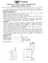
U-81 OCTAVO RECEIVER OPERATING INSTRUCTIONS
10
5 8 1
2a
6
4 7
9 2c3
2d2d
2b
2a
unbalanced mixer input. Make sure the Phantom Power on your mixing board in turned
off and the volume in turn down when making the audio connections. Start the receiver
VOLUME at minimum and adjust until the level is optimal.
• For each channel you wish to use, insert an audio cord with a XLR female plug into its
Balanced XLR out (9) jack on the back of the receiver. Plug the other end of this cord
into your amplier, effects or mixing board. The individual receiver outputs are all xed
mic level.
• The U-81 OCTAVO also has a MIX unbalanced output (10), which is a SUM line
level output of all the channels. To use it, just plug an audio cable with a 1⁄4” mono
plug into the MIX out (10) and plug the other end to your amplier or mixing board.
The front panel individual receiver volume controls (6) can be used to adjust any
channels level on the MIX out (10). Turn the volume controls on each of the channels
being used clockwise to near full gain. Adjust each volume up or down so that no
audio distortion is present when the ampier or mixer is set at their usual levels.
(Note: Turn the volume controls of any unused channel all the way off, full counter-
clockwise, so that only the channels being used are in the MIX output.)
• Your U-81 OCTAVO is now operational and ready to use. Now that you have completed
the above step, proceed to instructions for the UH-81 or UB-81 transmitters included
with your system.
Note:
• To prevent possible undesired noise during use, keep the volume controls of unused channels
(corresponding transmitter off) turned off in the amplier or the mixer. The audio should only be “live”
if the transmitter is on.
• As when making any connection, make sure the amplier or mixing board volume is at the minimum
level before plugging in the receiver to avoid possible sound system damage.
• Only one transmitter can be used with one receiver. It is not possible to use two transmitters on the
same frequency and mix the output of these transmitters into one wireless receiver.

6
7. UH-81 Transmitter Set Up
• Release the Battery cover (11) by pressing the locking tab and slide down as
per arrow, exposing the Battery holder (12). Insert two fresh AA alkaline or NiMH
batteries, observing the correct polarity as marked, and slide the battery cover back
on to the microphone. Make sure the cover is closed completely. Fresh alkaline
batteries can last up to 10 hours in use, but in order to ensure optimum performance,
it is recommended that you replace the battery after every 6-8 hours of use. NiMH
batteries should be replaced with fresh ones recharged fully (with separate charger, not
supplied, and as per its charging instructions) whenever low or dead battery status is
indicated as per the following.
• Turn on the UH-81 by sliding the ON/STDBY/OFF switch (13) to the STANDBY
position rst (transmitter on, audio muted) or the ON position (transmitter and audio
both on). The Battery indicator LED (14) will give a single quick ash, indicating
usable battery strength. In the case of dead or low batteries, the LED will either not
go on at all or will stay on continuously, indicating that the batteries should be replaced
with fresh ones. To preserve battery life, turn the transmitter off when not in use.
• The microphone is now ready to use. The RF Signal LED (7) on the corresponding
channel of the U-81 OCTAVO receiver should now be lit, indicating a received signal
from the same frequency transmitter. When ready to speak, slide the ON/STDBY/OFF
switch (13) to the ON position.
• Adjust the volume of the receiver as per the Connecting Audio Outputs, section 6 of
the U-81 OCTAVO receiver instructions above.
Note: Observe care in selecting P.A. volume, transmitter location and speaker placement so that acoustic
feedback (howling and screeching) will be avoided. Please also note the pickup pattern characteristics of
the microphone selected. Omni-directional mics pick up sound equally from all directions, and are prone
to feedback if not used carefully. Unidirectional mics, as provided with the UH-81, are more resistant to
feedback, but pick up sound sources best that are directly in front of the mic. Also, mics that are farther
from the sound source, such as lavaliers, require more acoustic gain and thus are also more prone to
feedback than close-source mics such as handheld or headworn models that are used close to the mouth.
UH-81 HANDHELD MIC TRANSMITTER
11 12
13
14

UB-81 BODYPACK MIC TRANSMITTER
8. UB-81 Transmitter Set Up
• Install by battery for the UB-81 transmitter by snap-opening the Battery door (15)
and inserting a fresh 9V alkaline or NiMH battery into the Battery compartment
(16), observing the correct polarity. Close the battery door to its original position
and completely cover the battery. Fresh alkaline batteries can last up to 10 hours
in use, but in order to ensure optimum performance, it is recommended that the
battery be replaced after 6-8 hours of use. A NiMH battery should be replaced with
another recharged fully (with separate charger, not supplied, and as per its charging
instructions) whenever low or dead battery status is indicated as per the following.
• Selecting Audio Input Operating Mode of the UB-81. The UB-81 is equipped with two
Input selector switches (17) located under the cover on the circuit board for selecting
the type of audio input you will be supplyin g to the transmitter. Select from the choice
of two positions: HEADWORN MIC and LAVALIER MIC (Condenser Microphones).
• There are two switches with selectable positions HM, LT together at same time.
To select inputs: (see chart on page 9)
A. Headworn Mic — set both switches to “HM”
B. Lavalier Mic — set both switches to “LT”
Note: Use only the input audio source as per the input selected with the internal Audio input selector
switches (17) or the audio will not be optimal–a muddy or distorted sound may result. Do not select the
GT setting as the U-81 receiver outputs are not suitable for wireless instrument use.
• Connection for the selected input to the UB-81 is provided with a 3.5 mm Locking jack
(18) for connecting the audio input selected. Connect either the Instrument cord (19)
or the Headworn mic (20) or Lavalier mic cord (21) as desired, according to the input
selected. To secure the connection, turn the slip ring on the plug clock wise to thread
it on the jack. To unplug, reverse the process. Slip the transmitter into a pocket or
Clip (22) it on to your clothes or instrument strap (if using the UB-81 as an instrument
transmitter).
• Turn on the UB-81 by sliding the ON/STDBY/OFF switch (23) to the STANDBY
position (transmitter on, audio muted) or the ON position (transmitter and audio both
on). The Battery indicator LED (24) will give a single quick ash, indicating usable
battery strength. In the case of a dead or low battery, the LED either will not go on at all
or will stay on continuously, indicating that the battery should be replaced with a fresh
one. To conserve battery life, turn unit off when not in use.
• The U-81 transmitter is now ready to use. The RF Signal LED (7) on the
corresponding channel of the U-81 OCTAVO receiver should now be lit, indicating a
received signal from the same frequency transmitter.
7

UB-81 BODYPACK MIC TRANSMITTER
• Adjust the volume of the receiver as per the Connecting Audio Outputs, section 6 of
the U-81 OCTAVO receiver instructions above. [Note: Observe care in selecting P.A.
volume, transmitter location and speaker placement so that acoustic feedback (howling
and screeching) will be avoided. Please also note the pickup pattern characteristics
of the microphone selected. Omni directional mics pick up sound equally from all
directions, and are prone to feedback if not used carefully. Unidirectional mics are more
resistant to feedback, but pick up sound sources best that are directly in front of the
mic. Also, mics that are farther from the sound source, such as lavaliers, require more
acoustic gain and thus are also more prone to feedback than close-source mics such
as handheld or headworn models that are used close to the mouth].
9. Microphone Use (with either a lavalier or headworn mic)
• Secure the connection from the Lavalier (21) or Headworn mic cord (20) by turning
the slip ring on the plug into the transmitter clockwise to thread it on to the jack. To
unplug, reverse the process. To use the lavalier mic, attach it at chest level. Do not
place it too close to the mouth–a distance of about six inches usually works best. To
use the headworn mic, place it on the head and adjust the boom so that the mic is
about one inch to the side of the front of the mouth. When ready to speak, slide the
ON/STDBY/OFF switch (23) to either the “STDBY or ON” position.
• For optimum performance, an Input level control (25) is provided. Adjust the gain by
turning the control with a small screwdriver. For lavalier mic use, it is recommended
that the level be set at about 1/2 maximum. For headworn mic use, it may be advisable
to turn the gain down somewhat, depending on the volume levels expected. In either
application, experiment and set for maximum possible gain without audible distortion
on the high level peaks.
Note: Turning down the gain too much can compromise the signal-to-noise and it is not recommended.
8

9
UB-81 BODYPACK MIC TRANSMITTER
18
25
22
15
16
17
24
23
19 20 21

CAUTIONS AND TROUBLESHOOTING
10. No Audio
If you are not getting audio through the U-81 OCTAVO system, slide the transmitter
POWER or MUTE (STDBY) switch to ON, carefully check all connection and system
setup. Check or replace transmitter battery. Check that the receiver is powered.
The receiver and transmitter must be set to operate on the same RF channel.
11. Audio Distorted or Unwanted Sound
Remove or turn off nearby RF sources (such as other wireless system, CB radio,
CD player, computer, digital effect, ect...) Check or replace transmitter battery.
12. Feedback
Observe care in selecting P.A. volume, transmitter location and speaker placement so
that the acoustic feedback (howling and screeching) will be avoided. Please also note
the pickup pattern characteristics of the microphone selected. Omnidirectional mics
pick up sound equally from all direction, and are prone to feedback if not used carefully.
Unidirectional mics are more resistant to feedback. However, pick up sound source
best that are directly in front of the mic. In addition, mics that are farther from the sound
source, such as lavalier, required more acoustic gain and thus are also more prone to
feed back than close-source mics such as handheld or headworn models that are used
close to the mouth.
13. RF Interference
If you encounter receiving interference (from other than an operating TV station),
often it can be checked by turning off each transmitter at a time to nd the source of
causing interferences. Please note that wireless frequencies are shared with other radio
services. According to FCC regulations, wireless microphone operations are unprotected
from interference from other licensed operations in the band. If any interference is
received by any Government or non-government operation, the wireless microphone
must be cease operation or change frequencies. The above statement is valid only for
use in the U.S.A.
14. Signal Loss
Reposition the receiver and perform walk-thought test. If audio dropouts persist, locate
“dead” spots and avoid them during performance. Check receiver MUTE level setting.
Check or replace transmitter battery.
10

TIPS
• If the Volume Control of the receiver is set too high, it may overdrive the input of the
mixer, causing distortion. Conversely, if the output is set too low, the overall signal-
to-noise ratio of the system may be reduced. Adjust the output level of the receiver
such that the highest sound pressure level going into the microphone causes no input
overload in the mixer, and yet permist the mixer level control to operate in the normal
range (not too high and not too low). This provides the optimum signal-to-noise for the
entire system.
•
Do not place the receiver antennas within 3 feet (1 meter) of another receiver or antennas.
• The receiver antennas should be kept away from any metal surface.
• For the best operation, the receiver should be placed at least 3 feet above the ground
and 3 feet away from a wall or metal surfaces. All operating transmitters should be
also at least 3 feet from the U-81 OCTAVO receiver. Keep antennas away from noise
source such as motors, automobiles, neon light, signal processor, computer, as well as
large metal objects.
• A single receiver cannot receive signal from two or more transmitters on the same
frequency simultaneously.
• For operation with an external antenna, low loss RF shielded cable should be used and
the length of the cable should not exceed 10 feet (3 meters).
• Position the receiver such that it has the least possible obstructions between it and the
transmitter. Line of sight is best!
• The transmitter and the receiver should be as close as possible but never less than
1 meter.
• Before inserting the batteries, please make sure that they are inserted according to the
correct polarity.
• Use only brand new alkaline batteries. Do not use “general purpose” batteries. When
batteries are weak, replace the batteries altogether at the same time. Do not mix and
use new and old batteries together.
• Turn the transmitter off when it is not in use. Remove the batteries if it is not to be used
for a long period.
• Headset and lavalier mic users, note that the microphone element can easily be
destroyed by the buildup of salts and minerals from perspiration and saliva. It is good
practice to put a windscreen on the mic at all times to protect it.
11

SPECIFICATIONS
OVERALL SYSTEM PERFORMANCE
RF Carrier Frequencies ........................................................ Selected factory installed frequencies
between 902-928MHz and 944-952MHz
Frequency stability ......................................................................... +/-0.005% (Crystal Controlled)
Audio Deviation ..............................................................FM +/-20kHz normal, +/-50kHz maximum
Frequency Response ......................................................................................... 20Hz-20kHz, -3dB
Dynamic Range...................................................................................................................... 120dB
Harmonic Distortion ........................................................................................... 0.5% THD, normal
Operating Range ...........................................................250 feet normal, 500+feet max line of sight
RECEIVER
Reception ...................................................................................................Mono antenna reception
Antennas ..................................................................................10” (25.4 cm) Dual adjustable angle
Mute Threshold ....................................................................................... -95dBm (none-adjustable)
Image Rejection ..................................................................................................... -70dB, minimum
Balanced output .................................................... Audio outputs: +/-24mV xed level (600 Ohms)
Unbalanced MIX output ........................................ Audio output: 360mV variable level (Open load)
Connectors ........................................................... Balanced: XLR, Unbalanced: 1⁄4” TS, Antennas:
TNC connector. DC in: 2.1mm barrel type
Indicators .............................................................................................Power On, RF and AF LEDs
Controls ...........................................................................Power ON/OFF buttons, Volume Controls
Power Requirement ................................................................................................15VDC/1200mA
Dimensions ................ 14.25” x 12” x 1.75 [W / D / H] (36.20 cm x 30.50 cm x 4.45 cm) [W / D / H]
Weight ................................................................................................................... 7.20 lbs (3.37 Kg)
TRANSMITTERS
Models Available .................................................................UH-81 Handheld and UB-81 Bodypack
Input Connectors
UH-81 Handheld .......................................Integral Nady DM-50D neodymium dynamic cartridge
UB-81 Bodypack .................................................................................... 3.5mm locking mini-jack,
Controls
UH-81 .......................................................................................................Power ON/STDBY/OFF
UB-81 ................................................................... ON/STDBY/OFF, Input Level Control (LT/HM),
selectable inputs—internal HM/LT switches
RF Power ........................................................... 20mW normal (50mW Maximum allowed by FCC)
Harmonics and Spurs ........................................................................................................ < -50 dB
Antennas ....................................................................................... UH-81/UB-81: Internal antennas
LED Indicators
UH-81/UB-81 .............................Single LED ashes once for “ON”, lights steady for ”LOW BAT”
Battery
UH-81 ..........................................................................................2xAA Alkaline or NiMH batteries
UB-81 ......................................................................................Single 9V Alkaline or NiMH battery
Battery Life ......................................................................................................8-10 Hours (Alkaline)
Dimensions
UH-81 .........................................................................................10.5”x 1.875” (26.7 cm x 4.8 cm)
UB-81 ...................................................................4.25” x 2.5”x 1.0” (10.8 cm x 6.4 cm x 2.5 cm)
Weight ...............................................................................................................................................
UH-81 .............................................................................................. 7.5 oz (213 g) without battery
UB-81 ................................................................................................3.1 oz (88 g) without battery
12

U-81 OCTAVO FREQUENCY PLAN
PLEASE NOTE:
902-928MHz and 944-952MHz
CH 14 CH 15 CH 16 CH 17
906.000 908.500 911.700 921.300
CH 10 CH 11 CH 12 CH 13
944.200 945.100 947.300 949.800
13
In order to ensure optimum operation of the U-81 receiver the antennas must
be installed as follows:
The antenna labeled “902-928MHz” should be mounted on the right antenna jack on
the rear panel and the antenna labeled “944-952MHz” on the left jack. If front mounting ,
please make sure to follow these guides so the correctly labeled antennas are placed on
the corresponding front panel jack connecting to the rear jacks.

14
In the U.S. If you are experiencing operational problems with your system, please refer to
the Support page at www.nady.com for assistance. Should your wireless system require
service, please contact the Nady Service Department at (510) 652-2411 for a Return
Authorization (R/A) Number and service quote (if out of warranty). Make sure the R/A
Number is clearly marked on the outside of the package that you are returning.
If your unit is out of warranty, please enclose a cashier’s check or money order (or pay
by credit card) per instructions by the Nady Service Department. Ship your unit prepaid
to: Nady Systems, Service Department, 6701 Shellmound Street, Emeryville, CA 94608.
Include a brief description of the problem you are experiencing. For service of a unit
under warranty, please follow the instructions in the following section.
Outside the U.S. For service and warranty matters please contact the Nady distributor in
your country through the dealer/store from which you purchased this product.
Do not attempt to service this unit yourself as
it can be dangerous and will also void the warranty.
SERVICE INFORMATION

15
Nady Systems, Inc. warrants to the original consumer purchaser that the above unit is
free from any defects in material or workmanship for a period of one year from the date
of original retail purchase. If any such defect is discovered within the warranty period,
Nady Systems, Inc. will repair or replace the unit free of charge, subject to verication
of the defect or malfunction upon return to Nady Systems.
To the extent permitted by law, any applicable implied warranties, including warranties
of merchantability and tness are hereby limited to one year from the date of purchase.
Consequential or incidental damages resulting from a breach of any applicable express
or implied warranties are hereby excluded. This warranty is in lieu of all other agreements
and warranties, general or special, express or implied and no representative or person
including a Nady dealer, agent, or employee is authorized to assume for us any other
liability in connection with the sale or use of this Nady Systems’ product.
Whereas some states do not allow limitations on how long implied warranties last, and
do not allow exclusion of incidental or consequential damages, the above limitations and
exclusions may not apply to you. This warranty gives you specic legal rights and you
may also have other rights which may vary from state to state.
This warranty is subject to the following conditions:
1) This system must have been purchased from an authorized Nady dealer and all
warranty service must be performed by Nady’s service department. Any service not
performed by Nady will automatically void this warranty.
2) Items not covered: physical damage resulting from improper handling of the unit in
transit from the factory by the shipper (Nady Systems is not responsible for such damage
and all such claims must be made against the shipping company by the consignee.);
defects caused by normal wear of the product (expendable parts are typically connectors,
cables, potentiometers, switches and similar components); damage or defects caused by
abuse, neglect, accident, failure to connect or operate the unit in any way that does not
comply with applicable technical or safety regulations, or improper repair, excessive heat
or humidity, alteration or unreasonable use of the unit, causing cracks, broken cases/
housings or parts; damage caused by leaking batteries; nish or appearance items; items
damaged in shipment en route to Nady Systems, Inc. for repair. The warranty is null and
void if any Nady serial number has been removed or defaced.
How To Obtain Service:
1) If factory service is required, you must contact our Service Department at
(510) 652-2411 for a return authorization (R/A) number. Make sure the R/A number is
clearly marked on the outside of your package. (Please note: if an R/A number is not
included, our Shipping Department cannot accept your package.)
2) Send the unit back to Nady Systems, Inc., 6701 Shellmound Street, Emeryville,
CA, 94608, freight pre-paid.You must include proof of date and place of purchase (i.e.,
photocopy of your bill of sale) or Nady cannot be responsible for repair or replacement.
Nady Systems, Inc. will not repair, nor be held responsible, for any units returned without
proper identication, return address, and RA number clearly marked on the package.
3) Per the above, Nady will perform all warranty service and return the unit to you at no
charge. Nady Systems will inform the buyer if product sent in does not meet the terms of
this warranty and will provide a quote for xing the unit and/or shipping it back exclusively
at the buyer’s expense.
ONE-YEAR LIMITED WARRANTY

6701 Shellmound Street
|
Emeryville, CA USA 94608
T 510.652.2411
|
F 510.652.5075
|
www.nady.com
/