
INSTALLATION
AND MAINTENANCE
BEFORE ASSEMBLlNG AND OPERATING THE FLUID
COUPLlNG, CAREFULL
y
READ ALL THE SAFETY AND
OPERATING INSTRUCTIONS REPORTED IN THIS MANUAL.
ALWAYS FOLLOW ALL THE INSTRUCTIONS AND ASSURE
THAT ALL THE OPERATORS STANDING BY THE
MACHINERY ARE WEARING ALL THE PROTECTIVE
EQUIPMENT NECESSARY FOR THE JOB TYPE AND
APPLlCATION BEING PERFORMED.
DO NOT USE THE MACHINERY IF YOU DO NOT
UNDERSTAND THESE INSTRUCTIONS, AND IMMEDIATELY
REFER TO THE MANUFACTURER OR THE CUSTOMER
SERVICE DESK FOR ASSISTANCE.
THE COUPLlNG MUST BE PROTECTED BY A CONVENIENT
COVER GUARD TO AVOID PERSONAL INJURY TO PEOPLE.
fI,XIAL AND RADIAL VENTILATION OPENINGS SHOULD BE
INCORPORATED IN THE GUARD HEAT EXCHANGE.
IF THE COUPLlNG IS FITTED WITH FUSIBLE PLUGS, THE
SAID OPENINGS SHOULD NOT BE DIRECTED TOWARDS
OPERATORS AND ANY HOT OR ELECTRICAL
INSTALLATION.
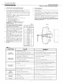
FLUID COUPLINGS
...KR... , ...KSD, EK
~
trasmissioni inilustrialí

UuJffi~~ITQill~rn
trasmlsslom Industrlall
FLUID COUPLlNGS
INSTALLATION AND MAINTENANCE
..KR.. - ..KSD series
INSTALLATION
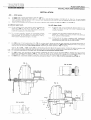
11
1.2
Fm KRG model, remove hall coupling G (Ilem 29
-
FIG. 4):
For KRD model, disassemble shaft D (item 31
-
FIG. 1b). In case fhe fluid coupling is stHI filled with oil, drain it or, to avoid possible
losses, position it vertically with lhe shalt D upwards; alter disassembling the shaft D, block the bearing carrier (item 14) with at least 2
nuts and washers (item 11 and 12),
Check that the threaded hole at the end of the motm 01'gearbox shalt complies with DIN 332 (TAB. A1-A2 and FIG. 4),
1,3
a) without taper bush
1A.a Fit the coupllng on the motor shaft by using a threaded bar
with S dia. (TAB. A 1 and A2) as shown in FIG. 1a, and
using 2 wrenches (hold a to avoid shaft rotatlon, and tum b
to draw the coupling on to the motm shalt),
1,5.a For a correcl assembly, lubricate the connecting surfaces
wlth oil 01' antiseizlng paste, For hot mouniing (not
recommended), do not overcome a temperature of 90°C,
Wllich causes Irreparable damages to oil seals,
b) with taper bush
1.4.
In case the bush is not provided with keyway (ílem 50 or 51
-
FIG. 1b), remove the key from motor or gearbox shaft
(reverse mounting).
1.5.b Carefully clean all surfaces contacting the bush by oil,
grease, etc., possibly usmg solvent, whether they belong to
motor, gearbox 01'fluid coupling.
1.6.b Fit the bush on the motor or gearbox shaft, intoducing a
screwdriver into the axial cut to make mounting easier;
assure that bush goes as far as the shaft shoulder.
For KRG series, fit half coupling (item 29
-
FIG. 4) on driven shaft, taking care that the shaft end does not protrude beyond face X.
Fit the fixing screw and the washer (items 25 and 26 for KR models; items 26 and 27 for KSD models) holding the motor or the gearbox
shaft still;
lock
the fixing screw with a torque wrench, respecting the torque reported in TAB. A 1 and A2.
Only for 13/15 KR KSD models (FIG. 3): fit the allan screw (item d) with flat washer (item e). Holding the motor or gearbox shaft
with a 38 mm wrench b 01'1the end c, lock the allan screw with a torque wrench a, respecting the torque reported in TAB. A2.
N.B.: For a correct assembly with the taper bush, strictly apply to the prescribed locking torque.
1.7
1.8
For KRG models, lock and peg the driven machine, positioning the motor as far as the gap K (FIG. 4) between the half couplings
reaches the Indicated values listed in TAB. C. The error on radius can be checked with a gauge and a straight-edge (FIG. 4): the
angular gap with a feeler, by rotating the coupling at 4 points 90° apart: the errors should not exceed those listed in TAB. C.
Fm KRD model, reassemble shaft D by locking nuts and washers (items 11 and 12 - FIG. 1b) at the prescribed torque (TAB. B).
-
I I
l;:
:h:=:>t
\_-,
I
-,
~
t
I
31 L. I
f-
I
11..12
1.9
FIG.1a
a
b
FIG. 2b (KRG)
FIG. 2a (KSD)
FIG.1b
26-27
i
¡

K... FIX SCREW
Steel
T orque
CK../CCK..
S
spec.
(Nm)
M6
10,9
~7-8
M8
35
M10 8,8
50
M10 10,9
70
9-11-12 M12
85
-
M16
8,8
205
13
-
15
~M20
400
KRD nu!
T
orque
CK../CCK,
11
(Nm)
7 - 8
M7
16
9 -11-12
M8
24
13
-
15
M10
50
17
-
19
21
-
24
M14
135
27
-
29
M16
205
34 CKRD
..KRG
Fluid
Dimensions in mm
coupling
K
R
A1- A2
6
02
0,2
0,3
7
-
8
10
2
~0,4
9 -11-12
20 0,35
13
BT
30
0,4
15
40
0,6
3
-
17-19
50
0,5
21
-
24
60
27 - 29
CT 80
..i.
0,8
0,6
34
CT 90
5
M12
85
9-11-12
M16
8,8
205
13
-
15
17
-
19
M20 400
21
-
24
27
-
29
M24
690
34
M36
1500
urnffiwUJ~urn~[[J
trasmlsslom Industrlall
FLUID COUPLlNGS
INST AL LATION AND MAINTENANCE
)
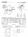
FIG.4
e
e
FIG.3
29
"",
'FIXING SCREW
MISALlGNMENT
AXIAL
RADIAL
ANGULAR
a
+ 1
-
0,5
R
A1
I
'
I
I
I I
I
I I
I I
¡
I
A2
TAS. A1
(without bush)
K... FIX SCREW Steel T orque
CK..lCCK..
S
spec
(Nm)
M6 10
M8 24
M10 50
TAS. A2
(with taper bush)
TAS. S
TAS.C
7-8
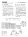
EK series (FIG. 5)
1.10) Assemble the flange A on the corresponding one of the
motor (of the gearbox far 6EK) and tighten bolts D.
1.11) Fit bell housing B onto the gearbox flange (electríc motor for
6EK) and tighten bolts E.
112) Flt the fluid coupling C on the motar shaft, hittíng wlth a soft
hammer on the shaft end X, as lar as it reaches the limit 01
the travel
1.13) For a correct fitting, it is important to lubricate surfaces
with antiseizing paste.
1.14) Fít the coupling / motor assembly into the gearbox hollow
shaft as lar as the Ilange A is connecled lo the bell housíng
B. then lix the bolts F.
1.15) Fit the sale guard G.
CD
FIG.5
:§)
@
@
@
2

TAB.D2
OIL QUANTITY (11.)
CK... 2 3
4
11
3.350
3.050 2.750
12
4.800 4.200 3.600
13
5.800 5.200 4.700
15
8.600
7.700 6AOO
17
13.60 12.80
1170
19
16.50
15.20 14.00
21
2300 21.30
1930
24
31.20
28.60 26.00
27
50.00
46.50 43.00
29
6300 59.00
54.00
34
92.50
88.50
83.50
TAB. D1
OIL QUAI'HlTY
(11.)
K... X 1 2
3 4
6
0.505 OA80 OA55
OA25 0.390
7
0.920
0.860 0.800 0730 0.650
8
1.510
1A05
1.295 1.190 1.080
9
1.950
1.820 1.690 1.550
1AOO
11
2.750
2.550 2.350
2.100 1.850
12
4100
3.875 3.575
3.250 2.900
13
5.200 4.850
4A50 4.050
3.600
15
7650
7.150 6600 6.000 5AOO
17
11.70 10.90
10.00 9.100
8.200
19
14.20
13.30 12.30
11.20 10.00
21
19.00
17.80
16AO 15.00
1350
24
28 AO
26.50
2460 22.60
20.50
27
42.00
39.00 36.00
33.50
31.50
29
55.00 51 00
47.00 44.00
41.50
34 82.50
76.60
70.60
66.20
62.50
TAB.D3
OIL QUANTITY (11.1
CCK...
3
4
15
9.30
8.00
17
16.36
14.86
19
18.76 16.86
21
2730
24.30
24
35A3 31.63
27
59.35 55.15
29
70.60 65.20
34 96.70
86 AO
SIZE
CUSIBLE PLUG
O.nolT]
l.,C,;?TorquE- iNmj
6 hb
12
1/2'
7
-
8
-
9
88
23
í/4
11
12
13
-
15
17-
19
ceo 29
31e'
21
,24
27
-
29
8E::
44
34
TIrnffiw~üllillu[]
trasmlsslom mdustnall
2. FLUID COUPLlNGS FILLlNG INSTRUCTIONS
KR... - KSD - EK SERIES
TI'ansfluld fluld coupllngs are no! supplled wlth 011
Therelore 11IS necessary to achleve the lollowlng pracedure:
2.1 Positlon the coupllng axls horizontally (FIG. 6). turn I1until the
X mark cast Into the houslng gets al tlle top vertical (maxlmum
fill). so that tlle 011plug (item 13) Is Inclined as shown III the
plcture
FIIIwlth 011untll it overflows out 01 the filler hole. Whlle fllllng,
gently rack the coupllng on its axls to make sure all air excess
IS vented out of the clrcult, 01', Ifposslble. remove also tlle cap
located In correspondence on the other rotor. The quantltles to
be Intraduced are those reported in TAB. 01.
Screw the cap (or both caps) at the prescribed torque (TAB.
E) and make sure no leakages occur; otherwise use thread
sealant on filler plug tllreads.
The líllings marked X-1-2-3-4 may be chosen by the opel'ators
to meet the be sI performance In terms 01 start-up and steady
runnlng operatíon.
With the maxlmum fill X a conditlon 01 mlnlmum slip and
maxlmum performance Is achieved: the startlng torque !
nominal torque ratlo gets higher (values generally comprised
between 1.8 and 2.2) decreaslng the 011quantlty Inslde the
coupling (fII11-2-3-4), the opposite result Is obtained.
HIgh slip causes overheating of 011contalned in the worklng
circuit, wlth a consequent decrease IIIoverall performance.
For normal operatlng conditions, use only ISO HM 32 (01'
equivalent SAE 10W) 011 types listed in TAB. O. At low
amblent temperatures, use ISO HM 10 (01' equivalen!
SAE 5W) ol!.
For vertical mounted appllcatlons, the coupllngs
recommended 011fllls are reported in TAB. 01.
22
2.3
24
2.5
2.6
27
TAB.D
FLUJD COUPLlNGS
INST ALLA TION
AND MAINTENANCE
CKR... / CCKR... - CKSD... / CCKSD... SERIES
Fluid couplillgS Wltll delayed IIIIchambel (CK series) have the mal n
purpose ot reduclng tlle startíng torque / nominal torque ratlo to
values up to 1.6 . Thls aspecl Is Improved by furtherly enlarglng the
delayed flll chambel (CCK series) up to values of 1.3 of the above
ratío
2.8 The startíng torque Ilmítatlon can be achieved by reducíng the
oil quantlty ínto the worklng clrcult (till 2-3-4) without
IIlcreaslng the slip value a! rated speed. In standstill positlon,
the delayed lill chambel actually COlltalllS par! 01 the oil II11that
Ilows to the working clrcuit durlng start up.
2.9 The 011 passes Irom the delayed IIII chamber to the workíng
clrcuit tllrough calibrated orifices (FIG. 7) oWlng to
centnlugal lorce. Starting Irom slze 21 K, such orillces
dlameters can be modílied even when the coupllng is already
assembled, slmply by replacing a calibrated bleed plug (item
b) screwed IIlto the valve (Item 57). When reassembling the
valve, always remember to flt the copper seal (Item 58) and
make sure no leakages occur.
This technical solution allows a very simple and easy
operation, to be achieved in a very short time and (what is
more important) without disassembling the fluid coupling.
210 For each starting torque ! nominal torque ratío, Transfluld can
give the exact oíl lill. The Iluíd coupllngs with a delayed fill
chamber are generally foreseen with fill 2 (TAB. 02), while
the ones equlpped wlth a double delayed fill chamber with
fill 3 (TAB. 03).
As fluid couplings are supplied without 011, lollow the
instructlons reported at par. 2.1 - 2.2 - 2.3
-
2.6.
211 For vertical mounted appllcatlons, the coupllngs
recommended oíl fills are reported In TAB. 02 and 03. Oue to
delayed lill chamber peculiarity, for vertical mounting the
chamber must be downward.
Aglp
Aral
BP
Castrol
RECOMMENDED OIL ISO HM 32 (SAE 10W) CLASSIFICATION
OSO 32 Chevron HYDRAULlC OIL 32 Mobil DTE 24
VITAM GF 32 El! ELFOLNA 32 Shell TELLUS OIL 32
ENERGOL HLP 32 Esso NUTO H 32 T exaco RANDO OIL HD 32
HYSPIN AWS 32 IP HYDRUS OIL 32 Total AZOLLA zs 32
FIG.6
~~.,.,
1/
.
/
~
/
..
57\.
...
:
.......
I
....
"',
(
"
",
~..-\
..
.~ \ .
:
I \
\
/
~// b
rl~
~
l
.
'"
...
:I~
.
~
..
¡
J
{1/
,
,
~
FIG.7
TAB.E
/
-,~.-
3

SYMPTOM
CAUSE
REMEDY
INSUFFICIENT OIL LEVEL
Check level and possibly
lop up
TOO HIGH
TOO MANY CONSECUTIVE START-UPS
Wail lor cooling belore reslarllng, or reduce number 01 slarl-ups
TEMPERATURE
HIGHER ABSORPTIONS THAN SPECIFIED ON TAG
Remove causes and I or reVlew dtmensionlng
HIGH AMBIENT TEMPERATURE
Improve coupllng ventllallon
FUSIBLE
PLUG
JAMMED OR OVERLOADED DRIVEN MACHINE
Remove causes
INTERVENTION
TOO NEAR HEAT SOURCE
Remove source or Introduce a shleld
TOO CLOSE PROTECTION COVER
Introduce convenlenl
alr
passages lo Improve heal exchange
OIL LEVEL
Check otllevel and IIII wllh Ihe rlgh! !ype 1I necessary
PERFORMANCE
I~eplace 1I neCeéSary (lAB
[)
al page
3)
OECREASE
OIL TYPE SPECIFICATION
VerlÍv whelhel rec,pondlng lo recommended 011 speclllcalions
AMBIENT
TEMPERATURE LOWE~; THAN O°C
carreel olllype (see par 26 al page
3)
INSUFFICIENT OPERA TING
FAUL TY MOTOR
Ct'led
mojo:
101811119:¡peed
(¡í
8léctrlc, check cOnnec1¡ons,!
SPEED
STAR / DEL TA INSERTION TIME
II
reaulred lime
100 lorlg, reduce 1I lo J s max
ANDIOR
EXCESSIVE SLIP
JAMMED OR BRAK.ED DRIVEI," MA.CHINE
RHnove cause~-
NOISE
ANO
ALlGI,MENT
Checl ailgnrTiél-:1I,p8ge i
r'2H
18)
VIBRA TION
FAUL TY BEARINGS
DléaSSerriDIe,
repiélce becHlrlQ;:,
(árld relatl\lE: SE:éJis)
WHISTLE
PROTECTIOI, COVER
~dTIé111ém Pd;~~;éJr~E:;<
between
cO\ler
and rn8chmE
UrnffiwfB~Qill~w
trasmlSSlom mdustrlall
3.
OPERA TION ANO MAINTENANCE
3.1 The normal operaling procedures have lo be carried on
keeping balance and temperature under control.
l\jol 10 damage Ihe coupling seals, lemperalure musl no!
overcome 90'C. For hlgher values, all Ihe seals bul Ihe rolaling
ones In Viton (items 15 and 20), have lo be made of a special
material 100.
As eVldenced in TAB. F where the causes and the relalive
remedies are reported, a high temperature value may be
caused by the following condillons:
a) Insufficlenl oil fill
b) Higher absorbed power Ihan motor rated power
C) HIgli Clmbíenl lemperature
d) High starting frequency per hour
e) Excesslve slartlng time
f) Too many consecutive start-ups
g)
Inadequate aír ventilation due to cover guardo
TRANSFLUID can supply all operating
data upon request.
3.2 After the first 20 days operalion, check the
oil fill (this operation to be carried out
with cold oil), the tightening of the screws,
the molor and the driven machine.
3.3 Repeal Ihe above checks every 6 months
-
For the KRG models, check the gap K
(TAS. C) of the elastic coupling. If the
torsional gap is excessive (about 2°),
replace the rubber elements.
3.4 Fluid couplings are supplied with fusible
plug al 145"C (120°C, 175°C and 198°C
settíngs are available upon request) as
shown in FIG. 14.
If the fusible plug blows al regular intervals
during normal service, then checks a), f) in
par. 3.1, and relalive T AS. F should be
considered.
3.5 In case the switching pin or the electronic
overload controller are mounted, check
that the dístances shown in FIG. 9 and 11
are wilhin the values imposed during the
assembly phase.
3,6 Oil should be replaced after 4000 hours
operation.
K.,I CK.,
Q
D withouj with
busl' bush
7
-
8
19
24
28
38
38
42
9-11-12
13
-
15
48
48
55
60
65 M27
65
75
80
80
90 M36
100
100
120
M45
135
150
17
-
19
21
-
24
27
-
29
34
TAB. F
FLUIO COUPLlNGS
INSTALLATION AND MAINTENANCE
4.
OISASSEMBL
y
4.1 Disassemble lile fixing screw (ilem 25 for I<R models; ilem 26
tor KSD models).
4.2 Screw threaded bal In10 tapped hole al Ihe em! of tlle iluld
coupllng and proceed as shown in FIG. 8 The said tllreaded
bar (dimensions Q reported in TAS. G) will pusl-I the coupling
off the molor sllaft.
4.3 For Ihe couplings assembled witll a laper bush, a very small
displacemenl is sufficienl to disengage the coupling from ItS
sea!. In case the laper bush is to be removed 100, a
screwdriver may be used to push inlo the keyway cut.
Do nol force into the taper bush to avoid damaging the
contact surfaces and then compromise the correct
reassembly of the par!.
TAB.G
FIG.8
M12
M"12
M14
M16
M20
M20
M27
4

Uu~ffiwg]lJllilli~rn
trasmlsslom Industrlall
5.
ACCESSORIES
Fluid couplings can be equipped, beyond the standard fusible plug.
with similar safety devices avoiding oil to escape, and that, in the
case 01 the electronic overload controller, can manage a lew more
palameters too.
The luslble plug is present as an element 01 further safety though
being set al a highel' temperature value.
51 SWITCHING PIN directly fitted 10 the couplíng covel plate
(FIG.9).
The electrical connection of the switch must have a lower
voltage than 230 V and a max current of 6 A (electrical
scheme details reported in FIG. 10).
Fllmly position the cam mounted lelay on its support, so tha!
the dlslance lrom the end 01 the switching prn is 6 mm.
11IS very imporlant to be within such a distance because, in
case the device is activated, the pln comes out owing 10
centrifugal lorce and intelcepts Ihe cam, switch es it on and
gives a conveníent outpul signal (to be used as an alarm or a
blocking impulse for the motor).
Notice that, in the configuratlon 01 an external driving impellel
the sWltching pin works in every condition; while, with an
external dliven Impellel' it can be correctly switched on only in
case of a slip increase due to overload 01 eccesslve load
tOlque absorption.
ALAR M ASSEMBLY SCHEME
Power SU
2
3
Switch
Optical
alarm
Acoustic
alarm
Common
FLUID COUPLlNGS
INSTALLATION AND MAINTENANCE
FIG.9
~?
-A
¡/
-Frrfl -;- TI---¡--ff
I \JJ \;1 \i/
I
c---
F'
=>
_..
'1 ,-'
..
n
1 I ¡I
1 1 I1
,
I
It
'
1 Ii
.
I I1
L_.JL /
L-.
lt)
-.:
<t,
. !
--+3~
i
I.i 135
:.
I I
I
U
._~;E!
~!}-/
kd
~
MELTING TEMPERATURE +1g"C
120°C SPEC. 1004. A
145"C SPEC. 1004. B
175°C SPEC. 1004. C
FIG.10
MOTOR STOP
ASSEMBL
y
SCHEME
Power su
Stop
button
Aux. contact
Relay
Start
button
Switch
°3
Solenoid
relay
Common
5

:z:
o
o
w o..
¡:::
o
w
:::o
« «
o..
I
Dé
o
UJ
>-
W
-'
FIG.13
Dé
o..
Dé
«
o
w
>-
>
UJ
o
ITrnmwg)Uilllfl~rn
trasmlsslom Industrlall
5.2 ELECTRONIC OVERLOAD CONTROLLER, formed by a
proximity sensor and a speed controller. It detects the output
speed of the fluid coupling continuously.
When the load torque increases, slip increases too and speed
consequently decreases.
II the speed reduces down to the set threshold far a longer
time than specified, thls is signalled by the intervention 01 the
internal relay.
The said electronic device can be mounted on all fluid
couplings where not installed O.E.M. It is only needed to
replace 2 bolts positioned at 180' around the external crown
(as shown in FIG. 11) with 2 special ones having a longer
screw and nut.
As shown in FIG. 11, it is necessary to position the proximity
sensor in line with the 2 bolts at 180°, at a lower distance than
5 mm, while the controller can be fitted in the most convenient
place, chosen by the user, within a maximum distance of 20 m
(making the proximity connecting wire adequately longer).
Before connecting to the electrical power supply, always
verify the voltage.
The electrical connections have to be achleved according to
the scheme reported in the detailed instructions 01 the same
electronic device, setting and/or adjusting all the functions on
the control panel, as shown In FIG. 12.
a) Blind time lor starting TC, wlth a screw regulation up to 120
s, avoiding the intervention of the alarm during the starting
phase.
b) Speed range DS, by means 01 a Dip-Switch to be
programmed on 5 and 8 positions, setting relay condition,
proximity type, reset system, acceleration or deceleration.
c) Speed threshold SV to be screw regulated from 1 to 10.
The value 10 corresponds to full range set with dip-switch.
d) Reset R, locally executable with a manual switch or remote
connections.
e) Delay time T setting screw regulation up to 30 s. This
lunction delays possible alarms caused by sudden torque
variations.
The lunction of the timers respect to the state of the relays is
diagrammed in FIG. 13.
Leds (FIG. 12) permitting to keep some vital lunctions under
control are also present on the panel:
1) Speed level overtaken SS with a red light switching on as
soon as the set threshold is overcome.
g)
Red alarm A lighting up when the internal relay switch es
on.
h) Green supply led ON pointing out that the device is
electrically supplied.
N.B.: For further details concerning electronic features and
connections, refer to the specific instructions supplied
with the device.
LED~
6
RELAY
FLUID COUPLlNGS
INST ALLA TION AND MAINTENANCE
FIG.11
~
¿I
:1
f'l
--~~~----
11
11
,1
l'
11
11
I~'
I!
I¿Y-~
:1
/-.
1:OS)
--.,/
I
I
f
~.
REL4Y-,
OFF
1" -IoN
PNP ¡,c=JIi
NPN
!J-=:J!
AUT
l'
a::=J!
\AAN
MIN
1).':" ~I
\AAX
(E 1]
'.' ~~\
RE~~T
I1
'~I
~ I1 /~
1,--/1-
~\,.:~~:/)
SET
POINT
FIG.12
-(=¡
T
- (D:'i\
1
'.:Y
j)
P%
MIN
IIL H 96000
I
-=:J'I
48.000
-=:J,I
24.000
rr--<DS)
..:=J,¡
12.000 .'-.,./
,c=JI~ 6.000
1
: =::~
3000
c=JI'
2 ~F
ic:JI I ~F
(]
A
@
11
[!4CJ~i)¡
ON
(]
,~
ON)
''-.,./
TC
TIME
T
T
I
--------
~--~------
ON ION
ON

GASKET KIT
FUSIBLE PLUG
RUBBER
SIZE
1186
1535
N 7018
BLOCK
K...
CK... CCK..
120"C
145"C Std
175"C
W
CODE
6
AV
AA
AB
AC
8
BT-A
7
BV
I
BT-S
8 CV
-
9
DV
SA
SS
SC
12
11
EV
ST-C
12KR FV
BV
12KSD
GV
CV
-
13
HV OV
ST-C
15 KV
EV
17
LV FV
CA CS
CC
ST-D
19
MV
GV
21
NV
HV
16
SToP
24
OV
KV
27KR QV
LV
CT-D/E350
29KR
RV MV
DA OB
DC
34KR SV
NV
CT-D/E425
K...
LOCKING TORQUE
CK...
Item 9
Item 10 ¡tem 34
CCK...
screw
Nm
screw
Nm
screwl Nm
6
M5
6
M6
10
--
7-8
M6
10
9 - 11
M8
24 M8
24 M8
24
12-13
15-17-19
M10 50
M10
50
21
M12
85
M10
50
24
M14
135
M14
135
27
29
M16
205
M14
135
34
M16
205
M20
400
TIrnffiw[B~[illJ~rn
trasmlsslom Industrlall
FLUID COUPLlNGS
INST ALLA TION AND MAINTENANCE
6. RECOMMENOEO SPARE PARTS (FIG. 16 -17)
When ordering spare parts. always specity modei and spec. nr. marked in the positions shown in FIG. 15 (27K, 29K and 34K have got
a plate reporting serial nr. too).
6.1 Seal kit lor KR / KSD items 4-5 (5a lar C ICC. versions)-6-15-20-41 (Items 15 and 20 In Viton, the others only upon request)
6.2 Fusible plug item 13a
6.3 Rubber element (lor ...KRG only) Item 28
6.4 Code numbers are shown on TAB. H
TAB H
7. O-RINGS ANO BEARINGSREPLACEMENT (FIG. 16-17)
N.B.: To hit the surtaces described in the tollowing, always use
plastic hammers.
7.1 Drain 011Irom coupling by unscrewlng the caps (Item 13) on
cover and delayed II11chamber, and Item 13a.
7.2 1I the Iluid coupllng Is supplled wlth a delayed 1111chamber,
remove it alter unscrewing item 34.
7.3 Unscrew nuts (Item 11), Insert 2 screw-drlvers in the slot
between bearlng carrier (item 14) and cover (Item 3), and act
to push bearing carrier and seal (item 15) out.
7.4 Unscrew bolts (Items 8
-
10), tap over the cover (item 3) to
remove It.
7.5 Remove bearing (item 16) wlth an extractor, as well as the 011
retalner (Item 47).
7.6 Remove the snap rlng (Item 18) and then the impeller (item 1).
7.7 Remove screws item 9 and plate washer Item 17. Bump on
plane B 01 the shalt (item 24 lor ..KR, Item 25 lar ..KSO) and
sllde the bearlng carrier (Item 23 lor ..KR, Item 24 lar ..KSD)
away wlth the seal (Item 20).
7.8 When reassembllng, proceed Inversely by replaclng bearlngs
and all seals. Use sealing paste between the plate washer
(Item 17) and the impeller (Item 2).
N.B.: To lock al! bolts and caps, reter to the listed torques:
TAB. K tor items 9 - 10 - 34
B 11
E 13
FIG.14
FUSIBLE PLUG
@@
.
I
120'C
145'C
@@
\---
Fusible alloy
175'C
198'C
TAB.K
FIG.15
Date (moth . year)
7

POS.
NAME
1
IMPELLER
(INNER)
2
IMPELLER
(OUTER)
3-30
COVER
4 O-RING
5-50
GASKET OR
O-RING
6
GASKET OR
O-RING
7-70
SCREW
8
SCREW
9
SCREW
10
NUT
11
NLJT
12
LOCK
WASHER
13
PLUG
130
FUSIBLE PLUG
14-140
BEAPINC CARRIER
15
SEAL
16
BALL
BEARINC
17
PL",TE
18
SNAP
RINC
19
SEAL
CARRIER
20
SEAL
21
BALL
BEARINC
22
SNAP
RlljC
23
BEARINC
CARRIER
POS. NAME
24 SHAFT
25
FIXING SCREW
26
WASHER
27
FLANGE
G
28 RUBBER BLOCK
29 HALF JOINT C
30 HALF JOINT
B
31
SHAFT
D
31.1
KEY
33
DF CHAMBER
34 SCREW
35 LOCK WASHER
36 SCREW
37
NUT
-~
38
LOCK WASHER
--
39
LOCK WA.SHER
40 PLATE
41
O-RII,C
47
OIL RETAINER
48
SCREW
49 LOCk W¡OSHER
57
VALV[ ¡OSSEMBL
y
58
CA.SKET
.--
TIrnffiw~[fDill~rn
trasmlsslom Industrlall
FLUID COUPLlNGS
INST ALLA TION AND MAINTENANCE
FIG.16
KRD/CKRD/CCKRD
(,~\
I \3~~
/
(~\ Only for 34
ff~
\27)~
Only lor 21-24
27-29-34
I
1 \
11
~
\
A \
(2?) \~)
KR
5 (í3
(47) (1~3)(3) (1 ) (
~
(íD'l (8) (130)
\
\
T
\
.
r?/~//~>/Ji,
I / / /'J
\ ////)í]
\ //
//
'
\ //j~)
/
3
~'
(15)
~,
"
(2-S(
",,
"
:=:
'"
"',
'"
(25\)
~'.
\:~~ ~
C' "
\
\~ -~
-
&
",
\12J
0
~'-..J23'1
~'CJ
"'-, ~
"
''.'''',
''(~
'''''''
\
"'
.
''(21)
", ~
~.'@
~)
CKR/CCKR
KRG/CKRG/CCKRG
Only lor 6
rn;J
Screw plug
Only lar 6-7-8
,--o
23)
.-.
Only lor 27-29-34
8

POS.
NAME
POS.
NAME
1 IMPELLER
(INNER)
21
BALL BEARING
2 IMPELLER
(OUTER)
22 SPACER
3-30 COVER
23
SNAP RING
4
O-RING
24
BEARING CARRIER
5-50
GASKET OR
O-RING
25 SHAFT
6
GASKET OR
O-RING
26
FIXING SCREW
7-70
SCREW
27
WASHER
8
SCREW
28
INTEGRAL SHEAVE
9
SCREw
29
BOLTED SHEAVE
10 NUT
30
SCREW
11
t"UT
31
WAVE SPRING
12 LOCK WASHER
32 COVER
13
PLUG
33 D.F CHAMBER
130 FUSIBLE PLUG
34
SCREw
14-140 BEARING CARRIER
35 LOCK
WASHER
15
SEAL
39
LOCK WASHER
16 BALL BEARING 47 OIL RETAINER
17 PLATE
50
LOCK WASHER
18
SNAP RING
57 VALVE A,SSEMBLY
20 SEAL
58 GASKET
UUJffiw~uurn~rn
trasmlsslom Industrlall
FIG.17
FLUID COUPLlNGS
INST ALLA TION AND MAINTENANCE
KSD
1 (4-1
60i (8) (G~ (2) (18)
/>--J
/~,-j//'._~//,-_/
//~//')~
/ //
/
/
/ /~~-
(/
// ////
//// /J,~
-
/~/
//
--!G\!
/ // ..~ ;;¿
/
//
/
/'
J29\
/ ~
_//
'-':'::;
)§
~r24'i
--
"--'---/
Only lar 6-7-8
Only lar 21-24
27-29-34
~\
(~
34
~
(35J~
\~(
3
\~
\
\
\
\.~) @
CKSD/CCKSD
KSI/CKSI/CCKSI
Only lar 17-24
22
~
21
B
23
@)
(28)
Only lor 6
i
Screw plug
TRANSFLUID s,r,l,
- Vla V, Montl, 19 - 20016 Pero (Milano) Italy - Tel. +3902339315,1
- Fax +39 0233910699 - E-mail tfitaly@tinit
9904
150 GB
9
-
 1
1
-
 2
2
-
 3
3
-
 4
4
-
 5
5
-
 6
6
-
 7
7
-
 8
8
-
 9
9
-
 10
10


Transfluid CKR Series Installation and Maintenance Manual
- Type
- Installation and Maintenance Manual
- This manual is also suitable for
Ask a question and I''ll find the answer in the document
Finding information in a document is now easier with AI
Other documents
-
 COTTON COLORS BLKM038 User guide
-
Vents KSD User manual
-
-
KlipXtreme KSD-336 User guide
-
KlipXtreme KSD-360 User guide
-
Ericsson D6XKRD90154 User manual
-
KlipXtreme KSD-370 User guide
-
 Crown Automotive 5012329AAK2 Installation guide
-
LG Optimus L3 II E425 User manual
-
 SIMA S.A. SPIRAL – 26 User manual


