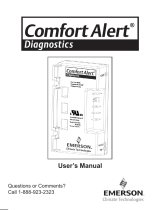
Emerson Comfort Alert 943-0038-02 User manual

Type
User manual

Emerson Comfort Alert 943-0038-02 can help you to monitor and analyze data from three phase Copeland Scroll™ compressors as well as thermostat demand. By doing so, the module can accurately detect the cause of electrical and system related failures and protect the compressor. A flashing LED indicator communicates the ALERT code and guides the service technician more quickly and accurately to the root cause of a problem.

Emerson Comfort Alert 943-0038-02 can help you to monitor and analyze data from three phase Copeland Scroll™ compressors as well as thermostat demand. By doing so, the module can accurately detect the cause of electrical and system related failures and protect the compressor. A flashing LED indicator communicates the ALERT code and guides the service technician more quickly and accurately to the root cause of a problem.

User’s Manual
543-0038-01, 543-0071-00, 543-0038-02,
943-0038-01, 943-0038-02
Comfort Alert
Commercial Diagnostics
2
Comfort Alert
Diagnostics – Faster Service And Improved Accuracy
The Comfort Alert diagnostics module is a breakthrough innovation for troubleshooting
and protecting three phase Copeland Scroll
compressors. The module installs easily in
the electrical box of the condensing unit near the compressor contactor. By monitoring
and analyzing data from the Copeland Scroll compressor and the thermostat demand,
the module can accurately detect the cause of electrical and system related failures and
protect the compressor. A ashing LED indicator communicates the ALERT code and
guides the service technician more quickly and accurately to the root cause of a problem.
NOTE: This module provides compressor protection and will shut down
the compressor when compressor damaging conditions are detected.
LED Description (Figure 1)
POWER LED (Green): indicates voltage is present at
the power connection of the module.
ALERT LED (Yellow): communicates an abnormal system
condition through a unique ash code. The ALERT LED
will ash a number of times consecutively, pause and then
repeat the process. The number of consecutive ashes,
de ned as the Flash Code, correlates to a particular
abnormal condition. Detailed descriptions of specific
ALERT Flash Codes are shown in two tables on pages 8
and 9 of this manual.
TRIP LED (Red): indicates there is a demand signal from
the thermostat but no current to the compressor is detected
by the module. The TRIP LED typically indicates the
compressor protector is open or may indicate missing
supply power to the compressor. A ashing TRIP LED
indicates the anti-short cycle timer is active, preventing
compressor from starting.
Product Speci cations
Operating Temperature: -40° to 150° F (-40° to 65° C)
Storage Temperature: -40° to 175° F (-40° to 80° C)
Power Supply Range: 18-30VAC, 48-62 Hz
Power Requirement: 2.0 VA nominal (without solenoid on – single stage)
7.0VA nominal (with solenoid on – two stage)
UL Restrictions: Use only with Class 2 circuits.
This 543-0038 module is designed only for three phase systems with Copeland Scroll
compressors that have internal overload protection. The software in this Comfort Alert
module is compatible with single stage (543-0038-02 or 943-0038-02) or two stage
(543-0038-01 or 943-0038-01) two-stage scroll systems.
Figure 1
UL File #SA8958
3
Hardware Installation
Four #8 or #10 self drilling or sheet metal screws, at least ½” length, are required for
installation of the Comfort Alert module. The maximum screw torque is 20 in.-lbs. Locate
the Comfort Alert module near the compressor contactor (wire routing for compressor
run, common and start wires will be easier in this position). Mount the Comfort Alert
module so all LEDs are visible from a comfortable viewing position. The module will
operate in any mounting orientation. For ease of reading labels, the module should be
oriented so that the green POWER LED is at the top.
Compressor Wire Routing (Figure 4)
The scroll compressor’s T1, T2 and T3 wires are routed through the holes in the Comfort
Alert module marked “T1,” “T2” and “T3.” The T2 wire need not be routed through the
module for it to operate properly.
WARNING
Hazardous voltage inside air conditioning system. Discon-
nect power before installing or servicing module. Module
must be installed and serviced only by quali ed personnel.
Figure 3
Model dimensions - Single Stage
Dimensions
A – 1.85 in (47 mm) D – 4.40 in (112mm)
B – 2.44 in (62 mm) E – 2.44 in (62 mm)
C – 1.46 in (37 mm)
Figure 2
Model Dimensions - Two Stage
4
24VAC Power Wiring
The Comfort Alert module requires a constant nominal 24VAC power supply.
The wiring to the module’s R and C terminals must be directly from the control
transformer. The module cannot receive its power from another device that will
interrupt the 24VAC power supply. Refer to wiring schematics in Figures 4, 5 and 6.
Thermostat Demand Wiring
The Comfort Alert module requires a thermostat demand signal to operate properly. The
thermostat demand signal input, labeled Y on the module, should be connected directly
to the compressor contactor coil so that when the coil is energized, the demand signal
is 24VAC. When the coil is not energized, the demand signal input should be less than
0.5VAC. Refer to wiring schematic in Figure 4.
An alternate thermostat wiring approach is to connect the demand signal directly to the
Comfort Alert and allow the module to control the contactor directly. Allowing Comfort
Alert to control the contactor directly will prevent voltage drops in long thermostat wire
runs. Refer to wiring schematic in Figure 5.
NOTE: Factory installed modules may have different thermostat demand signal
wiring. Follow manufacturer’s wiring instructions when replacing module.
System Controller Demand Wiring
The Comfort Alert module can also be connected to a system controller refer to Figure
6 for wiring schematics. The PROT terminal may be monitored by the controller instead
of providing protection if the controller shuts down the compressor on severe Alerts.
The 10kohm resistor must be added externally and forces the controller input to 24VAC
when the PROT terminal is open. When the PROT terminal is closed, the controller
input will be 0VAC.
NOTE: After the thermostat demand signal is connected, verify Y is phased
properly with C by measuring 24VAC across Y and C when demand is present.
Thermostat Second Stage Cooling Wiring
(Not applicable to single stage models 543-0038-02 and 943-0038-02)
For two stage applications, the Comfort Alert module requires a two stage thermostat
to operate properly. The Y2 thermostat wire should be connected to the Y2 input on
Comfort Alert.
While the compressor is running, Comfort Alert will provide power to the second stage
cooling solenoid inside the compressor after Y2 has been energized for 5 seconds.
Whenever the compressor is not running, Comfort Alert will not power the solenoid,
regardless of the state of Y2.
5
Figure 4 Thermostat Contactor Control
Y2
Y
L
R
C
PROT
DC SOL
CC
Y2
C
R
L
Y1
COMFORT ALERT
DIAGNOSTICS
MODULE
543-0038-00
INDOOR THERMOSTAT
Two-Stage Only
L1
L2
L3
3 Phase
208-575VAC
50/60Hz
HPCO
LPCO
Optional
T1
T2
T3
Two-Stage
Solenoid
Three Phase
Copeland Scroll
Compressor
Two-Stage Only
Y2
Y
L
R
C
PROT
DC SOL
CC
Y2
C
R
L
Y1
COMFORT ALERT
DIAGNOSTICS
MODULE
543-0038-00
INDOOR THERMOSTAT
Two-Stage Only
L1
L2
L3
3 Phase
208-575VAC
50/60Hz
HPCO
LPCO
Optional
T1
T2
T3
Two-Stage
Solenoid
Three Phase
Copeland Scroll
Compressor
Two-Stage Only
R
Schematic Abbrevation Descriptions
CC Compressor Contactor
HPCO High Pressure Cut Out Switch
LPCO Low Pressure Cut Out Switch
Note: Y2 and DC SOL are not applicable for models
543-0038-02 and 943-0038-02.
Schematic Abbrevation Descriptions
CC Compressor Contactor
HPCO High Pressure Cut Out Switch
LPCO Low Pressure Cut Out Switch
Note: Y2 and DC SOL are not applicable for models
543-0038-02 and 943-0038-02.
Figure 5 Comfort Alert Contactor Control
6
L Terminal Wiring
The L connection is used to communicate Alert codes to compatible White-Rodgers
thermostats. An icon on the thermostat display will ash at the same rate as the Comfort
Alert yellow Alert LED. The L terminal of the thermostat should be connected directly
to the Comfort Alert L terminal. Refer to White-Rodgers thermostat manuals for more
information.
DC SOL Connection
(Not applicable to single stage models 543-0038-02 and 943-0038-02)
The two pin DC SOL connector provides a connection to the Copeland™ two-stage
second stage compressor solenoid. This solenoid is internal to the compressor. This
24VDC solenoid will not operate properly if 24VAC is applied to the compressor solenoid
terminals.
To reduce the VA load of the solenoid on the system, Comfort Alert uses a phase control
method to reduce the DC voltage to the solenoid to the minimum level required to keep
the solenoid pulled in. As the 24VAC supply voltage varies, Comfort Alert intelligently
changes the solenoid DC voltage supply to minimize power consumption. A voltmeter
attached to the DC SOL output will measure 4-18VDC, when solenoid should be
energized, depending on the level of the 24VAC supply.
Y2
Y
L
R
C
PROT
DC SOL
CC
O2
I2
C
R
I1
O1
COMFORT ALERT
DIAGNOSTICS
MODULE
543-0038-00
SYSTEM CONTROLLER
Two-Stage Only
L1
L2
L3
3 Phase
208-575VAC
50/60Hz
HPCO
LPCO
Optional
T1
T2
T3
Two-Stage
Solenoid
Three Phase
Copeland Scroll
Compressor
Two-Stage Only
10 k Ohm Resistor
I1, I2 = Controller Inputs
O1, O2 = Controller Outputs
R, C = Controller Power
Figure 6 System Controller Schematic
Note: Y2 and DC SOL are not applicable for models
543-0038-02 and 943-0038-02.
7
PROT Terminal
The PROT terminal provides the compressor protection functionality for Comfort Alert.
If a compressor damaging code is active, the PROT terminal interrupts the common
leg of the compressor contactor coil. This terminal is rated for a maximum of 1 Amp (24
VA) and is only compatible with AC coils. The compressor contactor coil must use the
same supply voltage as the Comfort Alert power supply, “R” and “C”.The PROT terminal
will allow the compressor contactor to be energized whenever demand “Y” is present,
no alert codes are present and the anti-short cycle timer (3 minutes) is not active. The
PROT terminal will force the compressor contactor to be deenergized whenever “Y” is
not present. Certain Alert codes will trip and/or lock out the compressor if the condition
is serious and no cooling is being provided. The anti-short cycle timer is active on every
compressor shut down. If the demand “Y” is present while the timer is still active, the
PROT terminal will keep the compressor contactor from energizing until the timer is
complete. The red TRIP LED will ash while the compressor is held off.
Safety Cutout Devices
The Comfort Alert protection is not a substitute for safety cutout protective devices. For
best troubleshooting results automatic reset cutout switches should be used. Comfort
Alert monitors patterns of behavior and will protect the system and provide diagnostics
when multiple cutout events are detected.
Interpreting The Diagnostic LEDs
When an abnormal system condition occurs, the Comfort Alert module displays the
appropriate ALERT and/or TRIP LED. The yellow ALERT LED will ash a number of times
consecutively, pause and then repeat the process. To identify a Flash Code number,
count the number of consecutive ashes. Every time the module powers up, the last
ALERT Flash Code that occurred prior to shut down is displayed for one minute. If the
yellow ALERT LED is on solid, more than 2 amps are conducted through the PROT
terminal. The contactor coil may be shorted or the PROT terminal miswired.
Some ALERT codes indicate a compressor damaging condition and the Comfort Alert
module will shut down and lock out the compressor. Refer to the tables on pages 8 and 9
to identify ALERT codes that result in a lock out.
Installation Veri cation for Model 543-0038-00
To verify the installation of Comfort Alert is correct, a functional test can be performed.
Force a call for cooling. The compressor will not immediately begin to run. This is due to
the anti short cycle timer. The anti short cycle time lasts for 3 minutes, and is indicated
by ashing the Trip LED. After the anti short cycle timer expires, the compressor should
run. Monitor the ALERT and Trip LEDs. The Alert and Trip LEDs should remain off during
this portion of the test. Disconnect power to the compressor while the call for cooling is
8
Status LED Status LED Description Status LED Troubleshooting Information
Green “POWER” Module has power Supply voltage is present at module
terminals
Red “TRIP”
LED On Solid
Thermostat demand signal
Y is present, but the com-
pressor is not running
1. Compressor protector is open
2. Condensing unit power disconnect is
open
3. Compressor circuit breaker or fuse(s)
is open
4. Broken supply wires or connector is not
making contact
5. Compressor power wires not routed
through Comfort Alert
6. Compressor contactor has failed open
Red “TRIP”
LED Flashing
The anti-short cycle timer (3 minutes), in module is preventing compres-
sor restart.
still active. The TRIP LED will again ash for the duration of the anti short cycle time,
after the anti short timer expires, the Trip LED will illuminate and remain solid as long
as the compressor power remains disconnected and demand is still present. If the red
LED does not function as described, refer to Table 1 to verify the wiring.
Installation Veri cation for Models 543-0038-01, 943-0038-01, 543-0071-00,
543-0038-02, 943-0038-02
Disconnect power to the compressor and force a call for cooling. The red TRIP LED
will immediately come on solid. If the red LED does not function as described, refer to
Table 1 to verify the wiring.
*Note: For these models, the anti-short cycle feature will become active after one hour
of total run time or after 50 normal run cycles which ever comes rst.
9
Module locks out compressor when compressor damaging ALERT codes appear
Lockout ALERT codes are noted in the Status LED Description
During a compressor lock out, 24VAC power must be removed from module to manually reset
Yellow “ALERT”
LED On Solid
A short circuit or over
current condition exists on
PROT terminal.
1. Compressor contactor coil shorted.
2. Electrical load too high for PROT circuit
(maximum 1 Amp)
3. 24 V AC wired directly to PROT terminal
Yellow “ALERT”
Flash Code 2
System Pressure Trip
Discharge pressure out of
limits or compressor over-
loaded (if no high pressure
switch in system)
LOCKOUT
1. High head pressure
2. Condenser coil poor air circulation (dirty,
blocked, damaged)
3. Condenser fan is not running
4. If low pressure switch is open:
Refer to Code 3 for troubleshooting
Yellow “ALERT”
Flash Code 3*
*Code 3 lockout
is disabled for
543-0071-00
Short Cycling
Compressor is running only
brie y LOCKOUT
1. If low pressure switch is open:
a. Low refrigerant charge
b. Evaporator blower is not running
c. Evaporator coil is frozen
d. Faulty metering device
e. Condenser coil is dirty
f. Liquid line restriction ( lter drier
blocked if present)
2. If high pressure switch is open, go to
Flash Code 2 information
3. Intermittent thermostat demand signal
4. System or control board defective
Yellow “ALERT”
Flash Code 4
Locked Rotor
LOCKOUT
1. Low line voltage to compressor
2. Excessive liquid refrigerant in
compressor
3. Compressor bearings are seized
Yellow “ALERT”
Flash Code 5
Open Circuit 1. Condensing unit power disconnect is
open
2. Compressor circuit breaker or fuses are
open
3. Compressor contactor has failed open
4. High pressure switch is open and
requires manual reset
5. Broken supply wires or connector is not
making contact
6. Unusually long compressor protec-
tor reset time due to extreme ambient
temperature
7. Compressor windings are damaged
10
Yellow “ALERT”
Flash Code 6
Missing Phase
LOCKOUT
1. Compressor fuse is open on one phase
2. Broken wire or connector on one phase
3. Compressor motor winding is damaged
4. Utility supply has dropped one phase
Yellow “ALERT”
Flash Code 7
Reverse Phase
LOCKOUT
1. Compressor running backward due to
supply phase reversal
Yellow “ALERT”
Flash Code 8
Welded Contactor
Compressor always runs
1. Compressor contactor has failed closed
2. Thermostat demand signal not con-
nected to module
Yellow “ALERT”
Flash Code 9
Low Voltage
Control circuit < 18VAC
1. Control circuit transformer is overloaded
2. Low line voltage to compressor
Flash code number corresponds to a number of LED ashes, followed by a
pause and then repeated.
TRIP and ALERT LED’s ashing at the same time means control circuit voltage
is too low for operation.
Resetting Alert Codes
Alert codes can be reset manually and automatically. The manual method to reset an Alert
code is to cycle the power to Comfort Alert off and on. For automatic reset, Comfort Alert
continues to monitor the compressor and system after an Alert is detected. If conditions
return to normal, the Alert code is turned off automatically. ALERT codes that result in
a compresor lockout can only be reset manually. ALERT codes that result in a lockout
can only be reset manually.
NOTE: Comfort Alert cannot be applied on compressors that are powered by a
variable frequency drive. The changing frequency will cause nuisance codes to
appear.
11
NOTE: The correct Comfort Alert model must be used for the application (refer to
the Product Speci cation section on page 2). If the wrong model is installed, the
ALERT Flash Codes for system faults will function incorrectly: the Comfort Alert
module may indicate system faults that are not present or fail to indicate system
faults that are present.
NOTE: Miswiring the Comfort Alert module will cause false LED codes. Table 1
describes LED operation when the module is miswired and what troubleshooting
action is required to correct the problem.
Miswired Module Indication Recommended Troubleshooting Action
Green LED is not on, Determine if both R and C module terminals are
module does not power up connected. Verify voltage is present at module’s R and
C terminals. Review 24VAC Power Wiring (page 4) for
R and C wiring.
Green LED intermittent, Determine if R and Y terminals are wired in reverse.
module powers up only Verify module’s R and C terminals have a constant
when compressor runs source. Review 24VAC Power Wiring (page 4) for R
and C wiring.
TRIP LED is on but system Verify Y terminal is wired properly per OEM wiring
and compressor check OK diagram. Verify voltage at contactor coil falls below 0.5VAC
when off. Verify 24VAC is present across Y and C when
thermostat demand signal is present. If not, R and C are
reverse wired.
TRIP LED and ALERT LED Verify R and C terminals are supplied with 19-28VAC.
ashing together
ALERT Flash Code 3 Verify Y terminal is connected to 24VAC at contactor coil.
(Compressor Short Cycling) Verify voltage at contactor coil falls below 0.5VAC when
displayed incorrectly off.
ALERT Flash Code 5 or 6 Check that compressor T1 and T3 wires are through
(Open Circuit, Missing module’s current sensing holes. Verify Y terminal is
Phase) displayed connected to 24VAC at contactor coil. Verify voltage at
Incorrectly contactor coil falls below 0.5VAC when off.
ALERT Flash Code 8 Determine if module’s Y terminal is connected. Verify Y
(Welded Contactor) terminal is connected to 24VAC at contactor coil. Verify
displayed incorrectly 24VAC is present across Y and C when thermostat
demand signal is present. If not, R and C are reverse
wired. Verify voltage at contactor coil falls below 0.5VAC
when off. ReviewThermostat Demand Wiring (page 4)
for Y and C wiring.
Table 1
Warranty Information
Emerson Climate Technologies, Inc. warrants its enclosed diagnostic module to be
free from defects in materials and workmanship under normal use for a period of one
year from the date of purchase or twenty months from manufacture whichever comes
rst. During this period, Emerson Climate Technologies, Inc. will replace any defective
diagnostic module without charge.
This warranty is valid for the original purchaser from the date of initial purchase and is
not transferable. Keep the original sales receipt. Proof of purchase is required to obtain
warranty replacement. Dealers or service centers selling this product do not have the
right to alter, modify or in any way change the terms and conditions of this warranty.
This warranty does not cover normal wear of parts or damage resulting from any of the
following: negligent use or misuse of the product, use on improper voltage or current,
use contrary to the operating instructions, disassembly, repair or alteration by anyone
other than Emerson Climate Technologies, Inc. Further, the warranty does not cover
acts of God, such as re, ood, hurricanes and tornadoes.
EMERSON CLIMATE TECHNOLOGIES, INC. MAKES NO IMPLIED WARRANTIES
OF MERCHANTABILITY OR FITNESS FOR PARTICULAR PURPOSE WITH RESPECT
TO THE COMFORT ALERT MODULE.
Emerson Climate Technologies, Inc. shall not be liable for any incidental or consequential
damages caused by the breach of any express or implied warranty. Some states,
provinces, or jurisdictions do not allow the exclusion or limitation of incidental or
consequential damages or limitations on how long an implied warranty lasts, so the
above limitations or exclusions may not apply to you. This warranty gives you speci c
legal rights, and you may also have other rights that vary from state to state, or province
to province.
Units under warranty and in need of repair should be returned to an authorized wholesaler
or original equipment manufacturer.
Patent 6, 615, 594 and Additional Patents Pending
2005ECT-191 R6 (1/18) Emerson, Comfort Alert, Copeland and
Copeland Scroll are trademarks of Emerson Electric Co. or one of its
af liated companies. ©2018 Emerson Climate Technologies, Inc.
All rights reserved.
Patente 6, 615, 594 y patentes adicionales pendientes
2005ECT-191 R6 (1/18) Emerson, Comfort Alert, Copeland, Copeland Scroll y
Ultra Tech son marcas comerciales de Emerson Electric Co. o de una de sus
compañías liales.
© 2018 Emerson Climate Technologies, Inc. Todos los derechos reservados.
Información de Garantía
Emerson Climate Technologies, Inc. garantiza que su modulo de diagnóstico adjunto no
tendrá defectos de materiales o de trabajo bajo un uso normal por un periodo de un año
a partir de la fecha de compra o bien por veinte meses a partir de la fecha de fabricación,
tomando como válida la fecha de primer vencimiento. Durante este período, Emerson
Climate Technologies, Inc. recambiará cualquier módulo de diagnóstico defectuoso sin
cargo alguno.
Esta garantía es válida para el comprador original a partir de la fecha de compra inicial y
no es transferible. Guarde el recibo de venta original. Se requerirá prueba de la compra
para obtener el recambio. Los distribuidores o centros de servicio que vendan este
producto no tienen ningún derecho a alterar, modi car o cambiar de ninguna manera
los términos y condiciones de esta garantía.
Esta garantía no cubre el desgaste normal de partes o de daños que resulten de
cualquiera de los siguientes casos: uso negligente o mal uso del producto, uso con
voltaje o corriente inadecuados, uso contrario a las instrucciones operativas, desmontaje,
reparaciones o alteraciones no realizadas por Emerson Climate Technologies, Inc.
Además, la garantía no cubre actos de la naturaleza como incendios, inundaciones,
huracanes o tornados.
EMERSON CLIMATE TECHNOLOGIES, INC. NO REALIZA NINGUNA GARANTÍA
IMPLÍCITA DE COMERCIABILIDAD O AJUSTE PARA UN PROPÓSITO EN
PARTICULAR CON RESPECTO AL MÓDULO Comfort Alert.
Emerson Climate Technologies, Inc. no tendrá ninguna responsabilidad por daños
incidentales o consecuentes causados por la ruptura de cualquier garantía expresa
o implícita. Algunos estados o provincias o jurisdicciones no permiten la exclusión o
limitación de daños incidentales o consecuentes con respecto a la duración de una
garantía implícita; por tanto, las limitaciones o exclusiones antemencionadas pueden no
ser aplicables en su caso. Esta garantía le brinda derechos legales especí cos y usted
puede llegar a tener otros derechos según cada provincia o cada estado.
Las unidades cubiertas por esta garantía y que necesiten reparaciones deberán ser
enviadas a un mayorista autorizado o a un fabricante original del equipo.
11
AVISO: El cableado incorrecto del módulo Comfort Alert causará códigos de
LED falsos. El cuadro 1 describe la operación de los LED cuando el módulo está
cableado de forma incorrecta y qué se debe hacer para corregir el problema.
Indicación de Módulo Mal
Cableado
Acciones Recomendadas
El LED verde no está
encendido, el módulo no
se energiza
Determine que los terminales del módulo R y C estén
conectados. Veri que que haya voltaje en los terminales R y
C del módulo. Revise el Cableado de Corriente de 2 4 VCA
(página 4) para el cableado de R y C.
El LED verde destella, el
módulo se energiza sólo
cuando el compresor
funciona
Determine que los terminales R e Y estén cableados en
reversa. Veri que que los terminales R y C del módulo
tengan una fuente constante. Revise el Cableado de
Corriente de 4 VCA (página 4) para el cableado de R y C.
El LED DE DISPARO
(TRIP) está encendido
pero el sistema y el
compresor aparecen OK
Veri que que el terminal Y esté cableado correctamente
según el diagrama de cableado del fabricante original.
Veri que que el voltaje en la bobina del contactor caiga por
debajo de 0.5 VCA al estar apagado. Veri que que haya
4 VCA en todo Y y C cuando está presente la señal de
demanda del termostato. Si no, R y C están cableados en
reversa.
El LED DE DISPARO
(TRIP) y el LED de
ALERTA (ALERT)
destellan al mismo
tiempo
Veri que que los terminales R y C tengan un suministro de
1 9 a 8 VCA.
Código 3 de Destello de
ALERTA (Compresor en
Ciclado Corto) aparece
incorrectamente
Veri que que el terminal Y este conectado a 24 VCA en la
bobina del contactor. Veri que que el voltaje en la bobina
del contactor caiga a menos de 0.5 VCA al estar apagado
Código 5 ó 6 de
Destello de ALERTA
(Circuito Abierto, Falta
de Fase) indicados
incorrectamente
Revise que los cables T1 y T3 del compresor estén tendidos
a través de los ori cios sensores de corriente del módulo.
Veri que que el terminal Y esté conectado a 24 VCA en la
bobina del contactor. Veri que que el voltaje en la bobina
del contactor caiga a menos de 0.5 VCA al estar apagado.
Código 8 de Destello
de ALERTA (Contactor
Soldado) aparece
incorrectamente
Determine que terminal Y del módulo esté apagado.
Veri que que el Terminal Y esté conectado a 24 VCA en la
bobina del contactor. Veri que que haya 24 VCA en Y y C
cuando esté presente la señal de demanda del termostato.
Si no, R y C están cableados en reversa. Veri que que el
voltaje en la bobina del contactor caiga a menos de 0.5
VCA al estar apagado. Revise el Cableado de Demanda del
Termostato (página 4) para el cableado de Y y C.
Cuadro 1
10
El número de código de destello corresponde a un número de destellos del LED,
seguidos por una pausa y que luego se repiten.
Si los LED de ALERTA (ALERT) y DISPARO (TRIP) destellan al mismo tiempo, esto
signi ca que el voltaje del circuito de control es demasiado bajo para la operación.
Reseteado de Códigos de Alerta
Los códigos de alerta se pueden resetear manualmente y automáticamente. El método
de reseteado manual de un código de Alerta es hacer ciclar on y off la corriente que va
al Comfort Alert. Para el reseteado automático, el Comfort Alert continúa monitoreando
el compresor y el sistema luego de que se haya detectado una Alerta. Si las condiciones
vuelven a la normalidad, el código de Alerta se apaga automáticamente. Los códigos de
ALERTA que resultan en una traba del compresor sólo se pueden resetear manualmente.
AVISO: El Comfort Alert no puede aplicarse en compresores energizados por
un motor de frecuencia variable. El cambio de frecuencia hará que aparezcan
códigos molestos.
AVISO: Se debe usar el modelo correcto de Comfort Alert para la aplicación
(re érase a la sección Especi caciones del Producto en la página 2). Si se instala
el modelo incorrecto los Códigos de Destellos de ALERTA para fallas en el sistema
también funcionarán incorrectamente: el módulo Comfort Alert podría indicar fallas
del sistema que no existan o podría no indicar fallas existentes en el sistema.
Código 8
de Destello
de “ALERT”
(ALERTA)
Amarillo
Contactor Soldado El
compresor funciona
siempre
1. El contactor del compresor ha fallado cerrado2.
La señal de demanda del termostato no está
conectada al módulo
Código 9
de Destello
de “ALERT”
(ALERTA)
Amarillo
Voltaje Bajo Circuito
de Control < 18VCA
1. Transformador del circuito de control en sobre-
carga2. Bajo voltaje de línea al compresor
9
Código 3
de Destello
de “ALERT”
(ALER-TA)
Amarillo
*El Código 3
de TRABADO
está desacti-
vado para el
modelo
543-0071-00
Compresor en Cicla-
do Corto funciona
sólo brevementeTRA-
BADO
1. Si el interruptor de presión baja está abierto:a.
Carga de refrigerante bajab.
b. El ventilador del evaporador no funcionac.
c. La bobina del evaporador está con-geladad.
d. Dispositivo de medición con fallase.
e. La bobina del condensador está suciaf.
f. Restricciones en la línea de líquido ( ltro
secador bloqueado si estuviese instalado)
2. Si el interruptor de presión alta está abierto,
re érase a la información de Código 2 de
Destello
3. Señal de demanda del termostato intermitente
4. Tablero de control o sistema defectuoso
Código 4
de Destello
de “ALERT”
(ALER-TA)
Amarillo
Rotor Trabado TRA-
BADO
1. Bajo voltaje de línea al compresor
2. Excesivo refrigerante líquido en el compresor
3. Los cojinetes del compresor están aferrados
Código 5
de Destello
de “ALERT”
(ALER-TA)
Amarillo
Circuito Abierto 1. La desconexión de energía de la unidad de
condensación está abierta
2. El interruptor de circuito del compresor o los
fusibles están abiertos
3. El contactor del compresor ha fallado abierto
4. El interruptor de presión alta está abierto y
requiere un reseteado manual
5. Cables de suministro rotos o el contactor no
están haciendo contacto
6. Tiempo de reseteado del protector del compre-
sor inusualmente largo debido a temperaturas
ambientes extremas.
7. Los bobinados del compresor están dañados
Código 6
de Destello
de “ALERT”
(ALER-TA)
Amarillo
Falta de FaseTRA-
BADO
1. El fusible del compresor está abierto en una
fase
2. Cable o conector roto en una fase
3. Bobinado del motor del compresor dañado4. El
suministro ha caído una fase
Código 7
de Destello
de “ALERT”
(ALERTA)
Amarillo
Fase en Reversa-
TRABADO
1. El compresor funciona en reversa debido al
cambio en la fase de suministro
8
LED de
Estado
Descripción del LED
de Estado
Información de Detección y Arreglo de Fallas del
LED de Estado
Led Verde
“ENERGIA”
El modulo tiene
energía
Hay suministro de voltaje en los terminales del
modulo
Led Rojo
“TRIP”
(DISPARO)
Se
Mantiene ON
La señal de demanda
Y del termostato
está pre-sente, pero
el compresor no
funciona
1. El protector del compresor está abierto
2. La desconexión de energía de la unidad de
condensación está abierta
3. El interruptor de circuito o fusible(s) está
abierto
4. Cables de suministro rotos o el conector no
están haciendo contacto
5. Los cables de corriente del compresor no están
tendidos a través del Comfort Alert
6. El contactor del compresor ha fallado abierto
LED rojo
“TRIP”
(DISPARO)
destella
El temporizador de anti ciclo corto (3 minutos) del módulo está evitando el
re-arranque del compresor.
El modulo traba al compresor cuando aparecen códigos de ALERTA de daños al compre-
sor.Los código de ALERTA de traba se incluyen en la Descripción del LED de Estado-
Durante el trabado de un compresor, se debe retirar la energía de 4VCA para resetearlo
manualmente
LED
“ALERT”
(ALERTA)
Se Mantiene
ONAmarillo
Existe una condición
de sobrecorriente o
corto cir-cuito en el
Terminal PROT.
1. La bobina del contactor del compresor está en
corto.
2. Carga eléctrica demasiado alta para el circuito
PROT (máximo Amp)
3. 24 VCA cableados directamente al termi-nal
PROT
Código 2
de Destello
de “ALERT”
(ALER-TA)
Amarillo
Presión de Descarga
de Disparo de Presión
del Sistema fuera de
los límites o compre-
sor sobrecargado (si
no hay interruptor de
presión en el sistema)
TRABADO
1. Presión cabezal alta
2. Pobre circulación de aire en bobina del conden-
sador (sucia, bloqueada, dañada)
3. El ventilador del condensador no fun-ciona
4. Si el interruptor de presión baja está abierto:
Re érase al Código 3 para la detección y ar-
reglo de fallas
Veri cación de la instalación para los modelos 543-0038-01*, 943-0038-01*, 543-0071-00*
Desconecte el suministro energético al compresor y fuerce una llamada de enfriamiento. El LED DE
DISPARO se encenderá inmediatamente. Si el LED rojo no funciona de la manera descrita, consulte la
Tabla 1 para veri car el cableado.
*Nota: Para estos modelos, la función contra ciclo corto se activará después de una hora de tiempo total
de funcionamiento o después de 50 ciclos normales de funcionamiento, lo que suceda primero.
7
Terminal PROT
El terminal PROT suministra funcionalidad de protección al compresor para el Comfort Alert. Si un código de
daños del compresor está activo, el terminal PROT interrumpe el circuito derivado común de la bobina del
contactor del compresor. Este terminal tiene una asignación para un máximo de 1 amp (2 4 VCA) y sólo es
compatible con bobinas de CA. La bobina del contactor del compresor debe usar el mismo suministro del
voltaje que el Comfort Alert, “R” y “C”.
El terminal PROT permitirá que se energice el contactor del compresor cada vez que se encuentre presente
la demanda “Y”, cuando no haya códigos de alerta y cuando el temporizador de anti ciclo corto (3 minutos)
no esté activo. El terminal PROT forzará al contactor del compresor a quedar desenergizado cada vez que
“Y” no esté presente. Algunos códigos de Alerta se dispararán y/o trabarán al compresor si la condición es
seria y no se esté suministrando ningún código. El temporizador de anti ciclo corto estará activo en cada
apagado del compresor. Si la demanda “Y” está presente mientras el temporizador está todavía activo, el
terminal PROT evitará que contactor del compresor se energice hasta que termine el ciclo del temporizador.
El LED DE DISPARO rojo destellará mientras el compresor se mantenga apagado.
Dispositivos de Corte de Seguridad
La protección del Comfort Alert no es un substituto de los dispositivos de corte de seguridad. Para obtener los
mejores resultados en detección y arreglo de fallas se deben usar interruptores de corte de reset automático.
El Comfort Alert monitorea tipos de comportamiento y protege al sistema y suministra diagnósticos cuando
se detectan eventos de cortes múltiples.
Interpretación de los LED de Diagnóstico
Cuando se produce una condición anormal del sistema, el modulo Comfort Alert indicará la ALERTA
correspondiente y/o el LED DE DISPARO. El LED DE ALERTA amarillo destellará una cantidad de veces
consecutivamente, hará una pausa y repetirá el proceso. Para identi car un número de Código de Destello,
cuente el número de destellos consecutivos. Cada vez que el módulo se energiza, el último Código de Destello
de ALERTA que haya ocurrido antes del apagado aparecerá por un minuto. Si el LED DE ALERTA queda
rmemente activo se conducirán más de 2 amperes a través del terminal PROT. La bobina del contactor
puede estar en corto o el terminal PROT mal cableado.
Algunos códigos de ALERTA indican una condición de daños en el compresor y el módulo Comfort Alert
apagará y trabará al compresor. Re érase a los cuadros en las páginas 8, 9 y 10 para identi car los códigos
de ALERTA que resulten en un trabado.
Veri cación de la instalación para el modelo 543-0038-00
Se puede realizar una prueba funcional para veri car que la instalación del Comfort Alert es la correcta.
Fuerce una llamada de enfriamiento. El compresor no empezará a funcionar inmediatamente debido al
temporizador contra ciclo corto. El tiempo contra ciclo corto es de 3 minutos y se indica mediante el destello
del LED de disparo. Cuando se termina el tiempo el temporizador contra ciclo corto, el compresor debe
empezar a funcionar. Monitoree los LED de ALERTA y de disparo. Estos LED deben permanecer apagados
durante esta porción de la prueba. Desconecte el suministro de energía al compresor mientras la llamada
de enfriamiento esté todavía activa. El LED DE DISPARO destellará otra vez durante el tiempo contra ciclo
corto; después de que se termine el tiempo del temporizador, el LED de disparo se iluminará y permanecerá
ja mientras la energía del compresor permanezca desconectada y la demanda siga presente. Si el LED rojo
no funciona como se describe, consulte la Tabla 1 para veri car el cableado.
6
Cableado del Terminal L
La conexión L se usa para comunicar códigos de Alerta a los termostatos compatibles
con White-Rodgers. Destellará un ícono en la pantalla del termostato a la misma tasa
que la del LED de Alerta amarillo del Comfort Alert. El terminal L debe estar conectado
directamente al terminal L del Comfort Alert. Re érase a los manuales de termostatos
White-Rodgers para obtener una mayor información.
Conexión SOL DE CC
El conector SOL DE CC (DCSOL) de dos puntas suministra una conexión al solenoide
del compresor de segunda etapa Copeland Ultra Tech. Este solenoide es interno al
compresor. Este solenoide de 2 4 VCC no operará correctamente si se aplican 4 VCA
a los terminales del solenoide del compresor.
Para reducir la carga de VA del solenoide en el sistema, el Comfort Alert usa un método
de control de fase para reducir el voltaje de CC al solenoide al nivel mínimo requerido
para mantener el solenoide activo. Como el suministro de voltaje de 4 VCA varía, el
Comfort Alert inteligentemente cambia el suministro de voltaje de CC del solenoide para
minimizar el consumo de energía. Un voltímetro adosado a la salida CD SOL(SOL DE
CC) medirá de 4 a 1 8 VCC, cuando el solenoide debe estar energizado, dependiendo
del nivel de suministro de 4 VCA.
Figura 5 Esquema del Controlador del Sistema
Nota: Y2 y DC SOL no son aplicables para los modelos
543-0038-02 and 943-0038-02.
5
Figura 3 Control del Contactor del Termostato
Descripción de las Abreviaturas del Esquema
CC Contactor del Compresor
HPCO Interruptor de Corte por Alta Presión
LPCO Interruptor de Corte por Baja Presión
Figura 4 Control del Contactor del Comfort Alert
Nota: Y2 y DC SOL no son aplicables para los modelos
543-0038-02 and 943-0038-02.
Nota: Y2 y DC SOL no son aplicables para los modelos
543-0038-02 and 943-0038-02.
Descripción de las Abreviaturas del Esquema
CC Contactor del Compresor
HPCO Interruptor de Corte por Alta Presión
LPCO Interruptor de Corte por Baja Presión
  • Page 1 1
  • Page 2 2
  • Page 3 3
  • Page 4 4
  • Page 5 5
  • Page 6 6
  • Page 7 7
  • Page 8 8
  • Page 9 9
  • Page 10 10
  • Page 11 11
  • Page 12 12
  • Page 13 13
  • Page 14 14
  • Page 15 15
  • Page 16 16
  • Page 17 17
  • Page 18 18
  • Page 19 19
  • Page 20 20
  • Page 21 21
  • Page 22 22
  • Page 23 23
  • Page 24 24

Emerson Comfort Alert 943-0038-02 User manual

Type
User manual

Emerson Comfort Alert 943-0038-02 can help you to monitor and analyze data from three phase Copeland Scroll™ compressors as well as thermostat demand. By doing so, the module can accurately detect the cause of electrical and system related failures and protect the compressor. A flashing LED indicator communicates the ALERT code and guides the service technician more quickly and accurately to the root cause of a problem.

Ask a question and I''ll find the answer in the document

Finding information in a document is now easier with AI