Page is loading ...

Overview
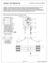
The AT-PWR15, shown in Figure 1, is an DC redundant power supply (RPS)
used with the AT-CV5000 DC chassis only. When installed, the module
operates in a standby mode. If the standard power supply fails or loses power,
the AT-PWR15 module changes from standby to active and provides all
power to the system to prevent a network failure.
Figure 1. AT-PWR15 Power Supply Module
Note
The power supply is hot-swappable. You can install it without powering
OFF the AT-CV5000 chassis.
Warning
This unit may have more than one input. To reduce the risk of electric
shock, disconnect all power inputs prior to servicing the unit.
POWER
FAULT
AT-PWR15
215
Related Documents
This installation guide is an abbreviated version of the installation procedure.
For details on the components, features, and functions of this product, refer to
the following documents on our web site, www.alliedtelesyn.com:
❑ AT-CV5000 Media Converter Chassis Installation Guide
(PN 613-50580-00)
❑ AT-S70 Management Software User’s Guide (PN 613-50617-00)
Package Contents
Make sure the following items are included in the shipping package. If any
item is missing or damaged, contact your Allied Telesyn sales representative
for assistance.
❑ One AT-PWR15 Redundant Power Supply (DC)
❑ This Installation Guide
❑ Warranty Card
Locations of the Power Supply Slots
Figure 2 illustrates the locations of the two power supply modules at the rear
of an AT-CV5000 DC model chassis.
Figure 2. Locations of the Power Supply Slots on the Rear Panel of
an AT-CV5000 DC Model Chassis
Before installing a power supply, please note the following guidelines:
Note
The AT-CV5000 chassis comes with two slots designated for the power
supplies; however, it is shipped with one standard power supply
preinstalled and one empty slot for an optional power supply. The
redundant power supply can be ordered separately from your ATI sales
representative.
Warning
Make sure that both power supplies (primary and redundant) are rated
for the same power ratings; otherwise, the power supplies may get
damaged.
Note
For centralized DC power connection, install only in a restricted access
location.
POWER
FAULT
AT-PWR15
AB
AT-CVFAN
A
AT-CVFAN
B
40-60VDC
WARNING
This unit might have more than one power input. To
reduce the risk of electric shock, disconnect all power
inputs before servicing unit.
FOR CENTRALIZED DC POWER
CONNECTION, INSTALL ONLY IN
A RESTRICTED AREA.
40-60VDC
WARNING
This unit might have more than one power input. To
reduce the risk of electric shock, disconnect all power
inputs before servicing unit.
FOR CENTRALIZED DC POWER
CONNECTION, INSTALL ONLY IN
A RESTRICTED AREA.
221
PS SLOT B - Redundant
PS SLOT A - Primary
Installing the AT-PWR15 Power Supply
To install the AT-PWR15, perform the following procedure:
1. Unpack the new AT-PWR15 module from its shipping container and store
the package material in a safe location.
Note
You must use the original shipping material if you need to return the
power supply module to Allied Telesyn.
2. Select the power supply slot in the AT-CV5000 chassis where you want to
install the AT-PWR15 power supply.
3. Loosen the two captive screws that secure the blank slot cover
(AT-CV5PNL2) of the selected power supply slot, and remove the blank
slot cover, as shown in Figure 3.
Figure 3. Removing the Power Supply Slot Cover
4. Slide the AT-PWR15 module into the RPS slot, as shown in Figure 4.
Figure 4. Inserting the AT-PWR15 Module into the Power Supply Slot
5. Secure the AT-PWR15 module to the AT-CV5000 chassis by using a
Phillips screwdriver to tighten the captive screws, as shown in Figure 5.
Figure 5. Securing the AT-PWR15 Module
B
1
0
0
-2
4
0
V
A
C
~
AT-CV5FAN
W
A
R
N
I
N
G
T
h
is
u
n
it
m
ig
h
t
h
a
v
e
m
o
r
e
th
a
n
o
n
e
p
o
w
e
r
in
p
u
t.
T
o
r
e
d
u
c
e
t
h
e
ri
s
k
o
f
e
le
c
t
r
ic
s
h
o
c
k
, d
i
s
c
o
n
n
e
c
t
a
ll p
o
w
e
r
F
O
R
C
E
N
T
R
A
L
I
Z
E
D
D
C
P
O
W
E
R
C
O
N
N
E
C
T
I
O
N
,
I
N
S
T
A
L
L
O
N
L
Y
I
N
A
R
E
S
T
R
I
C
T
E
D
A
R
E
A
.
B
218
B
AT-CV5FAN
B
W
A
R
N
I
N
G
T
h
is
u
n
it m
ig
h
t
h
a
v
e
m
o
r
e
t
h
a
n
o
n
e
p
o
w
e
r in
p
u
t.
T
o
re
d
u
c
e
t
h
e
ris
k
o
f e
le
c
t
r
ic
s
h
o
c
k
,
d
is
c
o
n
n
e
c
t
al
l
p
o
w
e
r
F
O
R
C
E
N
T
R
A
L
I
Z
E
D
D
C
P
O
W
E
R
C
O
N
N
E
C
T
I
O
N
,
I
N
S
T
A
L
L
O
N
L
Y
I
N
A
R
E
S
T
R
I
C
T
E
D
A
R
E
A
.
POWER
FAULT
AT-PW
R15
216
B
AT-CV5FAN
B
POWER
FAULT
AT-PWR15
W
A
R
N
IN
G
This unit might have more than one power input. T
o
reduce the risk of electric shock, disconnect all po
wer
FO
R
CE
N
TR
A
L
IZE
D
D
C P
O
W
E
R
C
O
N
N
E
CT
IO
N
,
IN
ST
A
L
L
ON
L
Y
IN
A
R
E
ST
R
IC
T
E
D A
R
E
A.
220
CONVERTEON™
Family
AT-PWR15 Redundant Power Supply (DC)
Installation Guide
Allied Telesyn, Inc.
www.alliedtelesyn.com
PN 613-50586-00 Rev A
1 2 3

Powering On a DC Powered Chassis
This section describes how to power on a DC powered AT-CV5000 chassis.
Warning
As a safety precaution, a 15 Amp circuit breaker should be installed at
the supply end of the cable to be used with this LAN equipment.
ALWAYS connect the wiring to the LAN equipment first before
connecting the wiring to the breaker. To avoid the danger of physical
injury from electrical shock, do not work with HOT feeds. Always be
sure that the breaker is in the OFF position before connecting the wiring
to the breaker.
Note
A tray cable is required to connect the power source if the chassis is
powered by centralized DC power. The tray cable must be an UL listed
Type TC tray cable and rated at 600 V and 90 degree C, with three
conductors, minimum 14 AWG.
1. Make sure that the ON/OFF power switch is in the OFF position.
2. Locate the two DC terminal blocks, labeled A and B, on the rear panel of
the chassis.
3. Starting from the left side of a terminal block, identify the positive, power
supply ground and negative terminals using the symbols below the
terminal block in Figure 6.
Figure 6. DC Terminal Block
4. With a 14-gauge wire-stripping tool, strip the three wires in the tray cable
coming from the DC input power source to 8mm ± 1mm (0.31 in., ± 0.039
in.), as shown in Figure 7.
250
40-60VDC
Warning
Do not strip more than the recommended amount of wire. Stripping
more than the recommended amount can create a safety hazard by
leaving exposed wire on the terminal block after installation.
Figure 7. Stripped Wire
5. Connect the power supply ground wire into the middle of the three
terminals; this is the terminal marked with the ground symbol. Inserting the
wire into the terminal and tightening the connection with a flathead
screwdriver, as shown in Figure 8.
Warning
When installing this equipment, always ensure that the power supply
ground connection is installed first and disconnected last.
Figure 8. Inserting Wires into a DC Terminal Block
6. Connect the +48 VDC (RTN) feed wire to the terminal block marked
+ (plus).
7. Connect the -48 VDC feed wire to the terminal block marked - (minus).
8mm ±1mm
(0.31in. ±0.039 in.)
B
W
R15
e
p
o
w
e
r inpu
t.
T
o
is
co
n
n
ec
t all po
w
er
FOR CENTRALIZED DC PO
WER
CONNECTION, INSTALL ONLY IN
A RESTRICTE
D AREA.
POWER
FAULT
AT-PWR15
AB
AT-CVFAN
A
AT-CVFAN
B
AT-PWR15
POW
ER
FAULT
40-60VDC
WARNING
This unit might have more than one power input. To
reduce the risk of electric shock, disconnect all power
inputs before servicing unit.
FOR CENTRALIZED DC POWER
CONNECTION, INSTALL ONLY IN
A RESTRICTED AREA.
40-60VDC
WARNING
This unit might have more than one power input. To
reduce the risk of electric shock, disconnect all power
inputs before servicing unit.
FOR CENTRALIZED DC POWER
CONNECTION, INSTALL ONLY IN
A RESTRICTED AREA.
256
Technical Specifications
Physical and Environmental
Dimensions (H x W x L) 3.67 cm x 10.1 cm x 17.1 cm
(1.45 in x 3.97 in x 6.73 in)
Weight 1.75 lbs
Operating Temperature 0° C to 40° C (32° F to 104° F)
Storage Temperature -25° C to 70° C (-13° F to 158° F)
Operating Relative Humidity 5% to 90% RH (non-condensing)
Storage Relative Humidity 5% to 95% RH (non-condensing)
Operating Altitude Range Up to 3,000 m (9,843 ft)
Electrical Ratings
DC Input Current: 40 to 60 VDC (6.0 A)
Nominal Input Frequency: 47-63 Hz
Electrical Safety and Emission Statement
Standards: This product meets the following standards when installed in compliant host equipment.
Emission FCC Class A, EN55022 Class A, VCCI Class A, C-TICK, CE
WARNING: In a domestic environment this product may cause radio interference in which case the
user may be required to take adequate measures.
Immunity EN55024
Electrical Safety UL60950-1 (
c
UL
us
), EN60950 (TUV), CAN/CSA C22.2 No. 60950-1-03
Copyright © 2005 Allied Telesyn, Inc. All rights reserved.
No part of this publication may be reproduced without prior written permission from Allied Telesyn Inc.
U.S. Federal Communications Commission
RADIATED ENERGY
Note: This equipment has been tested and found to comply with the limits for a Class A digital device pursuant
to Part 15 of FCC Rules. These limits are designed to provide reasonable protection against harmful
interference when the equipment is operated in a commercial environment. This equipment generates, uses,
and can radiate radio frequency energy and, if not installed and used in accordance with this instruction
manual, may cause harmful interference to radio communications. Operation of this equipment in a residential
area is likely to cause harmful interference in which case the user will be required to correct the interference at
his own expense.
Note: Modifications or changes not expressly approved of by the manufacturer or the FCC, can void your right
to operate this equipment.
Industry Canada
This Class A digital apparatus meets all requirements of the Canadian Interference-Causing Equipment
Regulations.
Cet appareil numérique de la classe A respecte toutes les exigences du Règlement sur le matériel brouilleur
du Canada.
4 5 6
/