Page is loading ...

69-2793EF-05
Owner’s
Guide
TH305
Non-programmable Thermostat

69-2793EF—05 2
Overview
About your new thermostat ..................................................................................... 3
Controls and display ................................................................................................... 4
Installation
Installation guidelines................................................................................................ 5
Mounting the thermostat......................................................................................... 6
Wiring..................................................................................................................................7
Configuration switches..............................................................................................8
Setup menu ..................................................................................................................... 9
Operation
Temperature display and setting....................................................................... 10
Power outage ............................................................................................................... 10
Appendices
In case of difficulty.................................................................................................... 11
Specifications .............................................................................................................. 12
3-year limited warranty........................................................................................... 13
Customer Assistance ............................................................................................... 14
Table of contents

3 69-2793EF—05
The TH305 thermostat is designed to control an electric heating
system such as a baseboard heater, a radiant ceiling, a convector or
a fan-forced convector.
This thermostat cannot be used with:
• a resistive load under 1.25 A
• a resistive load over 16.7 A
• a system driven by a contactor or a relay (inductive load)
• a central heating system
SUPPLIED PARTS
• One (1) thermostat
• Two (2) 6-32 mounting screws
• Two (2) solderless connectors
About your new thermostat

69-2793EF—05 4
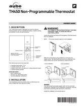
Controls and display
Temperature
display
Temperature
adjustment
buttons
Keypad lock
Heating intensity
Appears when the thermostat is
configured for a fan-forced
heater.

5 69-2793EF—05
TURN OFF POWER TO THE HEATING SYSTEM AT THE MAIN POWER
PANEL TO AVOID ELECTRICAL SHOCK.
• The installation must be performed by a qualified electrician and must
comply with electrical codes of your region.
• Do NOT install the thermostat in an area where it can be exposed to water or
rain.
• Avoid locations where there are air drafts (such as the top of a staircase or
an air outlet), dead air spots (such as behind a door), or direct sunlight.
• Do not install the thermostat on a wall section that conceals air ducts,
chimney pipes or stove pipes.
• Install the thermostat about 1.5 m (5 feet) high, on an inside wall facing the
heater.
• Install the thermostat onto an electrical box.
• This thermostat has tinned copper wires for line and load connections.
Special CO/ALR solderless connectors must be used if the thermostat will
be connected to aluminium wires.
• The thermostat wires are not polarized; either wire can be connected to the
load or to the power supply.
• Keep the air vents at the top and bottom of the thermostat clean and free
from obstructions.
Installation guidelines

69-2793EF—05 6
1) Loosen the screw and remove the faceplate of
the thermostat from its wallplate. (The screw
remains captive on the wallplate.)
2) Make the connections using solderless
connectors for copper wires. The thermostat
wires are non-polarized; this means either wire
can be connected to either terminal.
3) Install the wallplate to the electrical box.
4) Set the configuration switches on the back of
the thermostat’s faceplate (see page 6).
5) Install the faceplate of the thermostat back on
the wallplate and tighten the screw.
6) If there is a protective film or sticker on the
thermostat’s screen, peel it off.
7) Apply power to the thermostat. Verify the
installation by checking that the heater can be
turned On and Off by raising and lowering the
setpoint using the and buttons.
Mounting the thermostat

7 69-2793EF—05
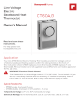
Wiring
Electrical
panel
Heater
Electrical
box
Thermostat
Electrical
panel
Heater
Electrical
box
Thermostat

69-2793EF—05 8
The configuration switches are on the back of the
thermostat. The factory settings are indicated by the
gray cells in the following table.
Configuration switches
Switches
1 Keypad lock a
a. The settings are locked. The temperature adjustment buttons
only allow you to view the temperature setpoint.
Off On
2 Cycle length b
b. Select short cycles in most cases as it provides better
temperature control. However, you must select long cycles if
you have a fan-forced heater. is displayed when long cycles
are selected.
Short Long
3 Temperature display format °C °F

9 69-2793EF—05
1) Press the and buttons simultaneously for three seconds to
enter the configuration menu.
2) Press the or button to set the displayed parameter.
3) Press the and buttons simultaneously for one second to
display the next parameter.
4) Press the and buttons simultaneously for three seconds to
exit the configuration menu.
NOTE: The thermostat will automatically save any changes made and return to
its normal display if you do not press any button for one minute.
Setup menu
Parameter Settings
Display and default setting
Minimum
setpoint
5 °C - 30 °C
(41 °F - 86 °F)
Maximum
setpoint
5 °C - 30 °C
(41 °F - 86 °F)

69-2793EF—05 10
The thermostat normally displays the actual temperature.
• To view the setpoint temperature, press
once on either temperature adjustment
button. The setpoint temperature will
appear for 5 seconds. The icon
appears when the setpoint is displayed.
• To change the setpoint temperature,
press the appropriate button until the
desired value is displayed.
• The screen is backlit for 10 seconds when any button is pressed.
During a power outage, the setpoint is saved in memory. You do not
need to adjust the temperature when power returns.
Temperature Display and Setting
Power outage

11 69-2793EF—05
In case of difficulty
PROBLEM SOLUTIONS
Thermostat’s
housing is hot.
This is normal. When the thermostat is running at full capacity, its
housing can reach 40 °C (104 °F).
Wrong
temperature is
displayed.
Rectify if any of the following conditions applies:
• The thermostat is exposed to air draft.
• The sticker on the thermostat’s screen has not been removed.
• The thermostat is located near or above a heat source such as
a light dimmer.
Display
disappears and
reappears after a
few minutes.
The thermal protection device on the heater has temporarily
opened. This can happen if the heater is obstructed by furniture
or curtain and has overheated, or if the heater’s thermal
protection device is too sensitive.
LO is displayed The measured temperature is below the display range. Heating is
activated.
HI is displayed The measured temperature is above the display range.
E1, E2 is
displayed
The thermostat performance is reduced due to a sensor error.
Please contact technical support for more information.

69-2793EF—05 12
Power supply: 120/208/240 VAC, 60 Hz
Minimum load: 1.25 A / 150 W @ 120 VAC, 60 Hz
1.25 A / 260 W @ 208 VAC, 60 Hz
1.25 A / 300 W @ 240 VAC, 60 Hz
Maximum load: 16.7 A / 2000 W @ 120 VAC, 60 Hz
16.7 A / 3465 W @ 208 VAC, 60 Hz
16.7 A / 4000 W @ 240 VAC, 60 Hz
Setpoint range: 5 °C to 30 °C (41 °F to 86 °F)
Display range: 0 °C to 60 °C (32 °F to 140 °F)
Resolution: ± 0.5 °C (± 1 °F)
Storage: -20 °C to 50 °C (-4 °F to 120 °F)
ICES-003 Class B Notice - Avis NMB-3, Classe B
This Class B digital apparatus complies with
Canadian ICES-003.
CAUTION: ELECTRONIC WASTE NOTICE
The product should not be disposed of with other household
waste. Check for the nearest authorized collection centers or
authorized recyclers. The correct disposal of end-of-life
equipment will help prevent negative consequences for the
environment and human health.
Specifications
273699
Energy Verified
Only

13 69-2793EF—05
Resideo warrants this product to be free from defects in workmanship or
materials, under normal use and service, for a period of three (3) years from the
date of first purchase by the original purchaser. If at any time during the
warranty period the product is determined to be defective due to workmanship
or materials, Resideo shall repair or replace it (at Resideo’s option).
If the product is defective,
(i) return it, with a bill of sale or other dated proof of purchase, to the place
from which you purchased it; or
(ii) call Resideo Customer Care at 1-800-468-1502. Customer Care will make
the determination whether the product should be returned to the following
address: Resideo Return Goods, Dock 4 MN10-3860, 1985 Douglas Dr. N.,
Golden Valley, MN 55422, or whether a replacement product can be sent to you.
This warranty does not cover removal or reinstallation costs. This warranty shall
not apply if it is shown by Resideo that the defect was caused by damage which
occurred while the product was in the possession of a consumer.
Resideo’s sole responsibility shall be to repair or replace the product within the
terms stated above. RESIDEO SHALL NOT BE LIABLE FOR ANY LOSS OR
DAMAGE OF ANY KIND, INCLUDING ANY INCIDENTAL OR CONSEQUENTIAL
DAMAGES RESULTING, DIRECTLY OR INDIRECTLY, FROM ANY BREACH OF
ANY WARRANTY, EXPRESS OR IMPLIED, OR ANY OTHER FAILURE OF THIS
PRODUCT. Some states do not allow the exclusion or limitation of incidental or
consequential damages, so this limitation may not apply to you.
THIS WARRANTY IS THE ONLY EXPRESS WARRANTY RESIDEO MAKES ON
THIS PRODUCT. THE DURATION OF ANY IMPLIED WARRANTIES,
INCLUDING THE WARRANTIES OF MERCHANTABILITY AND FITNESS FOR A
3-year limited warranty

© 2020 Resideo Technologies, Inc. All rights reserved.
This product is manufactured by Resideo Technologies, Inc. and its affiliates.
Tous droits réservés. Ce produit est fabriqué par Resideo Technologies, Inc. et ses sociétés affiliées.
www.resideo.com
Resideo Inc., 1985 Douglas Drive North,
Golden Valley, MN 55422
69-2793EF—05 M.S. Rev. 01-21 | Printed in United States
PARTICULAR PURPOSE, IS HEREBY LIMITED TO THE THREE YEAR
DURATION OF THIS WARRANTY. Some states do not allow limitations on how
long an implied warranty lasts, so the above limitation may not apply to you.
This warranty gives you specific legal rights, and you may have other rights
which vary from state to state. If you have any questions concerning this
warranty, please write Resideo Customer Care, 1985 Douglas Dr, Golden
Valley, MN 55422 or call 1-800-468-1502.
For assistance with this product please visit http://resideo.com
or call Customer Care toll-free at 1-800-468-1502.
Customer Assistance

Guide du
propriétaire
TH305
Thermostat non-programmable

69-2793EF—05 2
Aperçu
À propos de votre nouveau thermostat ............................................................. 3
Commandes et affichage ......................................................................................... 4
Installation
Consignes d'installation............................................................................................ 5
Installation du thermostat .......................................................................................6
Branchement .................................................................................................................. 7
Sélecteurs de configuration .................................................................................... 8
Menu de configuration ..............................................................................................9
Fonctionnement
Affichage et réglage de la température.......................................................... 10
Panne de courant ...................................................................................................... 10
Annexes
Problèmes et solutions ........................................................................................... 11
Fiche technique.......................................................................................................... 13
Garantie limitée de 3 ans....................................................................................... 14
Service à la clientèle................................................................................................. 16
Table des matières

3 69-2793EF—05
Le thermostat TH305 est conçu pour commander un appareil de
chauffage électrique tel qu’une plinthe électrique, un plafond
radiant, un convecteur ou un ventiloconvecteur.
Ce thermostat ne peut être utilisé avec :
• une charge résistive inférieure à 1,25 A
• une charge résistive supérieure à 16,7 A
• un appareil muni d’un contacteur ou d’un relais (charge inductive)
• un système de chauffage central
PIÈCES FOURNIES
•Un (1) thermostat
• Deux (2) vis de montage 6-32
• Deux (2) connecteurs sans soudure
À propos de votre nouveau thermostat

69-2793EF—05 4
Commandes et affichage
Température
Clavier
verrouillé
Apparaît lorsque le
thermostat est configuré
pour un ventiloconvecteur Boutons de
réglage de la
température
Intensité du chauffage

5 69-2793EF—05
METTRE LE SYSTÈME DE CHAUFFAGE HORS TENSION AU PANNEAU
ÉLECTRIQUE AFIN D'ÉVITER TOUT RISQUE DE CHOC ÉLECTRIQUE.
• L’installation doit être effectuée par un électricien qualifié et doit être
conforme aux codes de l'électricité en vigueur dans votre région.
• Ne PAS installer le thermostat à un endroit où il risque d’être exposé à l’eau
ou à la pluie.
• Éviter les endroits où il y a des courants d'air (comme dans le haut d'un
escalier ou une sortie d'air), où il manque de circulation d’air (comme
derrière une porte) ou qui sont directement exposés au soleil.
• Ne pas installer le thermostat sur un mur qui dissimule des conduits d’air ou
d’une cheminée.
• Installer le thermostat à environ 1,5 mètre (5 pieds) du sol, sur une cloison
intérieure faisant face à l’appareil de chauffage.
• Installer le thermostat sur une boîte électrique.
• Le fils du thermostat servant à la connexion de l’alimentation et de la
charge sont en cuivre étamé. Si vous les reliez à des fils d’aluminium, utiliser
des connecteurs spéciaux sans soudure CO/ALR conçus à cette fin.
• Les fils du thermostat ne sont pas polarisés; le sens du branchement n’a
donc aucune importance.
• Garder les ouvertures d’aération du thermostat propres et dégagées en tout
temps.
Consignes d'installation

69-2793EF—05 6
1) Dévisser la vis et séparer la façade du
thermostat de sa plaque murale. (La vis reste
captive sur la plaque murale.)
2) Faire le branchement en utilisant des
connecteurs sans soudure pour fils de cuivre. Les
fils du thermostat sont non-polarisés; le sens du
branchement n’a donc aucune importance.
3) Installer la plaque murale sur la boîte électrique.
4) Configurer le thermostat à l’aide des sélecteurs
à l’arrière de la façade (voir la page 6).
5) Retourner la façade du thermostat sur la
plaque murale et serrer la vis.
6) Enlever la pellicule autocollante de l’écran s’il y
en a une.
7) Mettre le système de chauffage sous tension.
Vérifier l’installation en s’assurant que le
système de chauffage puisse être activé et
désactivé en augmentant et en diminuant la
température de consigne à l’aide des boutons
et .
Installation du thermostat
/