Page is loading ...

HOLE ENLARGEMENT IN
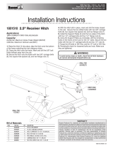
BED SILL DIAGRAM
HITCH WEIGHT: LBS.
INSTALL TIME: MINUTES
INSTALL NOTES:
Curt Manufacturing Inc., warrants this product to be free of defects in material and/or workmanship at the time of retail purchase by the original purchaser. If the product is found to be defective,
Curt Manufacturing Inc., may repair or replace the product, at their option, when the product is returned, prepaid, with proof of purchase. Alteration to, misuse of, or improper installation of
this product voids the warranty. Curt Manufacturing Inc.'s liability is limited to repair or replacement of products found to be defective, and specifically excludes liability for incidental or
consequential loss or damage.
19
90
DODGE RAM 1500, INCLUDING MEGA/CREW CAB AND ECODIESEL
4/26/2016
16306
*** DO NOT EXCEED VEHICLE MANUFACTURER'S RECOMENDED TOWING CAPACITY ***
Parts List
DESCRIPTIONPART NUMBERQTYITEM
LOCK WASHER1/2"181
.313" x 1.00 x 2.00" U-SHAPE SPACERCM-SP136
102
HEX NUT
1/2-13
183
FW, 12, ZPFW12104
1/2 - 13 x 1 1/2 WHEEL BOLT1/2 - 13 x 1 1/2 WB85
CARRIAGE BOLT1/2 - 13 x 2"106
FISHWIRE TOOL1/2"1
7
Parts List
DESCRIPTIONPART NUMBERQTYITEM
DRIVER SIDE FRONT WELDMENT16306-DSFWA1A
.375" PASSENGER SIDE FRONT PLATE 16306-PSF1B
.375" DRIVER SIDE REAR PLATE 16306-DSR1C
.375" PASSENGER SIDE REAR PLATE16306-PSR1D
3
1
4
2
5
7
- DRILLING REQUIRED
Mounting Rails
(Sold Separately)
Passenger Side
Frame Rail
Driver Side
Frame Rail
DRILL HOLE
(BOTH SIDES)
DRILL HOLE
(BOTH SIDES)
REAR OF VEHICLE
FRONT OF VEHICLE
B
D
C
A
DRILL 1" HOLE IN FRONT BED SILL TO INSTALL
NUTS AND WASHERS ON BED RAIL BOLTS
6

G ENERAL IN STRU C T IO N S FO R M O U N T IN G R A IL IN ST AL L A TIO N
TO O L S
3/16” drill 3/4” S ocket & O pen E nd W rench
17/32” drill 100 lb-ft Torque W rench
1” drill “C” C lam ps
1. T he following instructions should be used to mount the 5
th
w heel. Care and atte ntion to d etail w ill ensure a
quality installation. C heck parts against parts list to becom e fam iliar w ith parts in kit. (S ee Fig. 1)
2. Raise rear of truck high enough to allow jack stands to be placed under rear spring han ger bracket of truck. T his
will provide maxim um room to install the 5
th
wheel brackets.
W A R N IN G :
If the truck is raised, be su re that th e truck is properly blocked and restrained to prevent
the truck from fa lling. Failure to do so may result in the truck su ddenly fallin g, causin g
d eath or serious injury .
3. D o not install m ounting rails over plastic bed liners. P lastic bed liners m ust be cut out of the w ay. M ounting
rails may be installed on spray in liner. N o te: C onsult installer for recom mended curing tim e.
4. U se only the supplied bolts, nuts, and washers to install this kit.
5. Sp ecific instructio ns for m ost co m m o nly used vehicles are included. If these instructions do not apply to your
vehicle, be sure that eac h end of each base rail is co
nnected to the vehicle fram e. E ach fram e bracket m ust be b olted
to the vehicle fram e w ith two bolts, unle ss optional weld is used.
C A U T IO N :
These instructions are guid elines only. A ctual installation is the respon sibility o f the
installer an d the ow ner. A lw ay s m easure truck and trailer before installing hitch to be
su re that th ere is clearance at th e cab and at the b u mper to allow for turn s.
T o prevent the trailer from hitting the cab w ith the trailer turned 90°, the center of the hitch sho uld be at least 52”
from the back of the cab w hen using a lo ng bed truck. (Actual distance required w ill depend on trailer width and
king pin locatio n.) Short bed (M inim um 38” fro m b ack cab to axle center line) trucks require a minim u m of a 1 3”
extended pin box for regular m aneuvers and do not apply.
6. M easurements are given from Rear E dge of truck bed to rear edge of the m ounting rail closest to the Rear Edge
of truck for m ost vehicle app lications (See Fig. 2).
7. C enter hitch betw een fender w ells and m ake sure rails are square. A d just p osition of rails until both
diagonal measu rem en ts are the same. T his should allow installation of a gooseneck or other 5
th
w heels to
these rails (See F ig. 2).
C A U T IO N :
C heck for obstru ctions before drilling. F ailure to d o so could result in damaged fuel or
brake lines, structural m e m bers, etc. C U R T M A N U FA C T U R IN G does its best to
com m unicate tow veh icle m anufa cturer chang es; how ever, it is ultim ately the
responsibility of the installer to prevent dam age due to in stallation.
8. D rill 10 holes identified in Fig. 2. (H ole location w ill vary for individ ual vehicle applicatio ns.) D rill all holes
with 3/16” drill and enlarge them w ith a 17/32” drill. A lways use sharp d rill bits. A 3/16” pilot hole w ill greatly
speed drilling larger holes. Install 1/2” carriage bolts into holes. Install 5/16” thick slotted spacer above or below
bed to fill corrugations in bed floor.
N O T E:
U sing the 1” drill bit, drill access holes in botto m of bed sill to install nuts and washers onto rail b olts.
9. Secure bolts thro ugh m o unting brackets with serrated w ashers, lock washers, and hex nuts. Secure the other
four bolts thro ugh the bed with flat w ashers, lock washers, and nuts.
For Installation A ssistance or T echnical Help, C all 1-800-798-0813

10. Drill two holes in frame for each bracket. Select the holes which will give the greatest spread between bolts.
Install eight 1/2”-13x1-3/8” ribbed neck bolts, (thread pointing out), lock washers, and hex nuts. Tighten nuts until
bolt heads seat. Lubrication of knurls of all rib neck bolts is recommended.
Note:
On vehicles with heavy duty suspensions, check for interference with bolts where brackets are mounted to
frame. If interference with suspension spring results, cut bolt flush to nut outboard of frame or use weld option.
WARNING:
DO NOT lubricate threads. It may cause bolt failure.
CAUTION:
Check for obstructions before drilling. Failure to do so could result in damaged fuel or
brake lines, structural members, etc. CURT MANUFACTURING does its best to communicate
tow vehicle manufacturer changes; however, it is ultimately the responsibility of the installer
to prevent damage due to installation.
CAUTION:
It is important that 17/32” drill be used for holes in chassis frame as rib neck bolts
may break if too small a hole is used and neck may not grip if too large a hole is used.
11. Torque all nuts to 110 lb-ft
12. Pull wire provided to pull rib neck bolts through frame as needed per application
Drill locations will vary. See individual installation for location
Use mounting channel/cross member assembly to position rails (not included).
Fig. 2 ** Diagonal Measurements must be the same for smooth
Operation of 16500 rolling units **
Each mounting rail
must have a bolt in
either of the marked
holes. Check for
obstructions before
drilling.
Measure diagonal from
same reference point.
Measurement should
be the same.
Choose (10) holes
identified by black
dots that correspond
with your individual
vehicle configuration.
Rear edge of
truck bed to rear
edge of mounting rail

DODGE ’09 AND NEWER 1500, INCLUDING MEGA/CREWCAB
IMPORTANT NOTES FOR THIS INSTALLATION:
1. **Rib neck bolts will need to be pulled through access holes in frame with supplied pull wire (see below).
2. Do not drill thru both wall of
frame. Drill only thru wall of
frame to which bracket is
mounted.
3. It is very important that
brackets in Row 2 are against
rear side of Bed Sill as shown.
Due to dimensional instability
in Bed Sill placement with the
Dodge truck, interference
could result when drilling in
Row 3. Observe caution note
below and double check all
areas prior to drilling.
4. *Due to tubular frames
having thinner walls than
previous C channel frames,
extra caution needs to be
used when mounting with the
optional welding.
CAUTION!
Check for obstructions before drilling. Failure to do so could result in damaged fuel or brake lines, structural members, etc.
CURT MANUFACTURING does its best to communicate tow vehicle manufacturer changes; however, it is ultimately the
responsibility of the installer to prevent damage due to installation.
Front
of
Vehicle
Measure from rear
edge of truck bed to
rear edge of mounting
rail
Rear Edge of
Truck Bed
(Not Tailgate)
Drill (2) center holes
shown in addition to
(8) holes for
mounting plates and
other hardware.
Install 1/2" carriage
bolts,u-shaped spacers
above or below bed
to fill bed corrugation,
and bolt plate below
bed with washers and
nut.
29" for 67" and 76" box
31" for 96" Box
Mounting Channel
*Optional weld
pattern
.25 2
.25 2 *
King Pin Center
approx. 1-1/2" forward
of axle center
Axle Center
Bed Sill
Bed Sill
Rear Mounting Bracket
.25 2
.25 2
*
Forward Mounting Bracket
Row 1 Row 2 Row 3 Row 4
drill 1" access
hole in bottom
of bed sill
/