Klutch NTEMCDV25-DK Owner's manual
- Category
- Power tools
- Type
- Owner's manual
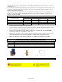
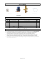
Klutch NTEMCDV25-DK is an electronic drain valve designed to drain condensation from tank reservoirs of air compressors, air dryers, condensate separators, and air filters. It features a 4 mm orifice, operates at a maximum pressure of 230 PSI, and has an operating temperature range of 40°F to 140°F. The unit is powered by 115 VAC and comes with a power cord.
Here are some of the capabilities of the Klutch NTEMCDV25-DK:
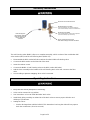
- Automatic draining: The unit automatically drains condensation from the tank reservoir when the water level reaches a certain point. This helps to prevent the tank from overflowing and causing damage to the compressor or other equipment.
Klutch NTEMCDV25-DK is an electronic drain valve designed to drain condensation from tank reservoirs of air compressors, air dryers, condensate separators, and air filters. It features a 4 mm orifice, operates at a maximum pressure of 230 PSI, and has an operating temperature range of 40°F to 140°F. The unit is powered by 115 VAC and comes with a power cord.
Here are some of the capabilities of the Klutch NTEMCDV25-DK:
- Automatic draining: The unit automatically drains condensation from the tank reservoir when the water level reaches a certain point. This helps to prevent the tank from overflowing and causing damage to the compressor or other equipment.


-
 1
1
-
 2
2
-
 3
3
-
 4
4
-
 5
5
-
 6
6
-
 7
7
-
 8
8
-
 9
9
-
 10
10
-
 11
11
-
 12
12


Klutch NTEMCDV25-DK Owner's manual
- Category
- Power tools
- Type
- Owner's manual
Klutch NTEMCDV25-DK is an electronic drain valve designed to drain condensation from tank reservoirs of air compressors, air dryers, condensate separators, and air filters. It features a 4 mm orifice, operates at a maximum pressure of 230 PSI, and has an operating temperature range of 40°F to 140°F. The unit is powered by 115 VAC and comes with a power cord.
Here are some of the capabilities of the Klutch NTEMCDV25-DK:
- Automatic draining: The unit automatically drains condensation from the tank reservoir when the water level reaches a certain point. This helps to prevent the tank from overflowing and causing damage to the compressor or other equipment.
Ask a question and I''ll find the answer in the document
Finding information in a document is now easier with AI
Related papers
Other documents
-
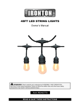 Ironton Outdoor String Lights, 48ft., 120 Volts, 21.6 Watts Owner's manual
-
 Strongway Wall-Mount Workstation Fan Owner's manual
-
 Strongway 49886 Owner's manual
-
Ingersoll-Rand IRN 7.5/5.5 kW Operation and Maintenance Manual
-
 Eternal GU195(M) Installation & Operation Manual
-
LG LP070CED1 Owner's manual
-
 Eternal GU195S/508211195 Installation & Operation Manual
-
-
Friedrich WS08D10A User manual
-
Husky L13HPD User guide


