Page is loading ...

Thank you very much for choosing a Roughneck™ Product! For future reference, please
complete the owner’s record below:
Model: _______________ Purchase Date: _______________
Save the receipt, warranty and these instructions. It is important that you read the entire manual
to become familiar with this product before you begin using it.
This machine is designed for certain applications only. The distributor cannot be responsible for
issues arising from modification. We strongly recommend this machine is not modified and/or
used for any application other than that for which it was designed. If you have any questions
relative to a particular application, DO NOT use the machine until you have first contacted
distributor to determine if it can or should be performed on the product.
For technical questions, please call 1-800-222-5381.
INTRODUCTION
PUMP: Electric self-priming rotary vane pump, equipped with by-pass valve and built-in filter
MOTOR: Asynchronous motor, single phase, 2-pole, closed type (Protection class IP55),
self-ventilating
The pump is designed to run on 120V, 60HZ power and supply a flow rate of up to 22 GPM (80
LPM) with diesel or light oils.
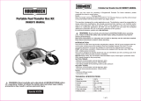
TECHNICAL SPECIFICATIONS
GENERAL SAFETY REGULATIONS
WARNING: Read carefully and understand all INSTRUCTIONS before operating.
Failure to follow the safety rules and other basic safety precautions may result in serious
personal injury.
Save these instructions in a safe place and on hand so that they can be read when required.
Keep these instructions to assist in future servicing.
WARNING: The warnings, cautions, and instructions discussed in this instruction
manual cannot cover all possible conditions or situations that could occur. It must be
understood by the operator that common sense and caution are factors that cannot be built
into this product, but must be supplied by the operator.
1. Keep the work area clean and dry. Damp or wet work areas can result in injury.
2. Keep children away from work area. Do not allow children to handle this product.
3. Store idle equipment. When not in use, tools and equipment should be stored in a dry
location to inhibit rust. Always lock up tools and equipment, and keep out of reach of children.
4. Use the right tool for the job. Do not attempt to force small equipment to do the work of
larger industrial equipment. There are certain applications for which this equipment was
designed. It will do the job better and more safely at the capacity for which it was intended.
Do not modify this equipment, and do not use this equipment for a purpose for which it was
not intended.
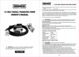
22 GPM FUEL PUMP
OWNER’S MANUAL
22 GPM FUEL PUMP OWNER’S MANUAL
WARNING: Read carefully and understand all
INSTRUCTIONS before operating. Failure to
follow the safety rules and other basic safety
precautions may result in serious personal injury
Item# 24925
1 of 4
Voltage
Frequency
Power
Flow Rate
120 Volts
60 Hz
540 Watts
22 GPM
Inlet/Outlet
Max. Suction Lift
Discharge
Max. Total Head
1in.
8 1/2ft.
56 1/2ft.
65ft.

22 GPM FUEL PUMP OWNER’S MANUAL 22 GPM FUEL PUMP OWNER’S MANUAL
5. Check for damaged parts. Before using this product, carefully check that it will operate
properly and perform its intended function. Check for damaged parts and any other condi-
tions that may affect the operation of this product. Replace damaged or worn parts immedi-
ately.
6. Do not overreach. Keep proper footing and balance at all times to prevent tripping, falling,
back injury, etc.
7. DO NOT use the equipment when tired or under the influence of drugs, alcohol, or medica
tion. A moment of inattention while operating this equipment may result in serious personal
injury.
8. Industrial applications must follow OSHA requirements.
SPECIFIC OPERATION WARNINGS
WARNING: Improper use or installation of this product can cause serious bodily injury
or death.
NOT FOR USE WITH LIQUIDS SUCH AS GASOLINE, ALCOHOL, EXPLOSIVES, CORROSIVES
AND FLAMMABLE, ALIMENTARY LIQUIDS.
Do not use the unit in an explosive environment.
Do not use the unit next to flammable liquids (gasoline, alcohol, etc.).
Do not use the unit in closed environments in the presence of gasoline, LPG or methane fuelled
vehicles.
Always wear fuel-resistant gloves and clothes during diesel delivery and wash hands with water
and soap at the end. Clean fuel spills at once to avoid slips and/or pollution.
Always wear suitable clothes and use suitable protective devices when cleaning, especially
when removing dust or waste. Always use aspirators when cleaning fuel spills.
Never place hands or limbs under moving parts.
WARNING: To ensure safe and efficient operation, it is essential to read and follow
each of these warnings and precautions.
1. DO NOT smoke near pump or use pump near an open flame. Fire could result.
2. Disconnect power to pump before servicing pump.
OPERATING CONDITIONS
1. ENVIRONMENTAL CONDITIONS
Temperature Min -4°F (-20°C)/ Max +140°F (+60°C)
Relative Humidity: Max. 90%
WARNING:
The temperature limits should be applied to the pump components and must be respected to
avoid possible damage or malfunction.
2. ELECTRICAL POWER SUPPLY
The AC pump must be supplied by a single-phase alternating current line whose nominal values
are shown in the table TECHNICAL SPECIFICATIONS above. The maximum acceptable
variations from the electrical parameters are:
Voltage: ± 5% of the nominal value
Frequency: ± 2% of the nominal value
2 of 4
WARNING:
Power from lines with values outside the indicated limits can damage the electrical compo-
nents.
WARNING:
DO NOT KEEP THE PUMP WORK IN BYPASS CONDITION MORE THAN 2 MINUTES.
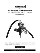
3. FLUIDS PERMITTED/ FLUIDS NOT PERMITTED
PERMITTED:
Diesel fuel or light oils at a viscosity of from 2 to 5 cST (at a temperature of 98.6°F/37°C)
Minimum Flash point (PM): 131°F/ 55°C
INSTALLATION
1. PRELIMINARY INSPECTION
• Check that the machine has not suffered any damage during transport or storage.
• Clean the inlet and outlet openings, removing any dust or residual packing material.
• Make sure that the motor shaft turns freely.
• Check that the electrical specifications correspond to those shown on the identification plate.
2. POSITIONING THE PUMP
• The pump can be installed in any position (pump axis vertical or horizontal).
• Attach the pump using screws of adequate diameter for the attachment holes provided in the
base of the pump.
WARNING:
Do not install pump where flammable vapors can be present.
3. CONNECTING THE HOSE
• Before connection, make sure that the hoses and the suction tank are free of dirt and thread
residue that could damage the pump and its accessories.
• Before connecting the delivery hose, partially fill the pump body with diesel fuel to facilitate
priming.
Suction Hose
• Minimum nominal recommended diameter: 1in.
• Nominal recommended pressure: 145 PSI / 10 bar
• Use a hose suitable for functioning under suction pressure.
Delivery Hose
• Minimum nominal recommended diameter: 3/4in.
• Nominal recommended pressure: 145 PSI / 10 bar
3 of 4
NOT PERMITTED
Gasoline (Petrol)
Inflammable liquids with PM < 131°F/55°C
Liquids with viscosity > 20 cST
Water
Liquid food products
Corrosive Chemicals
Solvents
RELATED DANGER
Fire - explosion
Fire - explosion
Motor overload
Oxidation of the pump
Contamination
Corrosion of the pump
Injury to people
Fire – explosion
Damage to gasket seals
DANGER
Electrical shock hazard.
Electrical wiring should be done by a licensed electrician in
compliance with local, state and national electrical code,
ANSI/NFPA 70, 30, 30A as appropriate.
Proper ground must be provided to avoid the possibility of
electrical shock. Failure to comply with this warning could
result in serious injury and/or loss of property.

22 GPM FUEL PUMP OWNER’S MANUAL 22 GPM FUEL PUMP OWNER’S MANUAL
WARNING:
1. It is the installer’s responsibility to use tubing with adequate characteristics. Tubing
unsuitable for use with diesel fuel can damage the pump, injure persons and cause pollution.
2. Use oil resistant pipe sealant or Teflon® Tape on all pipe threads.
3. Check all the connections before each use. Tighten them if necessary. Loosening of the
connections (threaded connections, flanging, gasket seals) can cause serious ecological and
safety problems.
4. CONSIDERATIONS REGARDING DELIVERY AND SUCTION LINES
DELIVERY
The improper application of the length of the tubing, the diameter of the tubing and the installed
line accessories may create unexpected large back pressure which may cause the (partial)
opening of the pump bypass and consequently reduce the flow rate.
To reduce system resistance, it is recommended to use shorter tubing and/or tubing with a 1in.
diameter.
SUCTION
The pump will prime to a height of 6.5 feet (2 meters). On tanks with a suction height over 6.5
feet., a foot valve may be required on the bottom of the suction tube to hold the fluid in the
tube. Do not install the pump with a height higher than 9.8 feet (3 meters), or the pump will lose
its prime.
The pump can work with pressure at the inlet as high as 7 PSI (0.5 bar). At a higher level,
bubbling (cavitation) can begin, with a consequent of loss of flow rate and increase of system
noise.
Keep the suction filters clean. Once clogged, filters increase system resistance.
The tank must be vented, or the pump may not prime or may lose its prime due to a vacuum in
the tank.
WARNING: In the case that the suction tank is installed higher than the pump
installation, it is recommended to install an anti-siphon valve to prevent accidental diesel fuel
leaks. Care should be taken during the installation process in order to control the back
pressure.
DAILY USE
• If using flexible tubing, attach the end of the tubing to the tanks. In the absence of an
appropriate slot, solidly grasp the delivery tube before beginning dispensing.
• Before starting the pump make sure that the delivery valve is closed (dispensing nozzle or
line valve).
• Turn the ON/OFF switch to ON. The bypass valve allows functioning with the delivery closed
for only brief periods.
• Open the delivery valve, solidly grasping the end of the tubing.
• Close the delivery valve to stop dispensing.
• When dispensing is finished, turn off the pump.
WARNING:
1. Functioning with the delivery closed is only allowed for brief periods (2 minutes maximum).
After use, make sure the pump is turned off.
2. Do not rest suction tubing on bottom of tank.
Lack of electric power
• A lack of electric power, with the consequent of accidental stopping of the pump, can be
caused by:
• A safety device tripping
4 of 4
In either case, act as follows before servicing the pump:
• Close the delivery valve
• Attach the end of the delivery to the slot provided on the tank
• Turn the ON/OFF switch to the OFF position
MAINTENANCE
The pumps are designed and constructed to require a minimum of maintenance.
• On a weekly basis, check that the tubing joints have not loosened, to avoid any leakage.
• On a monthly basis, check the pump body and keep it clean of any impurities.
• On a monthly basis, check and keep the pump filter clean and any other filters installed.
• On a monthly basis, check that the electric power supply cables are in good condition.
• Under normal working conditions the noise emission from all models does not exceed the
value of 70 dB at a distance of 3 feet from the electric pump.
TROUBLE SHOOTING
Problem
The motor
is not turning
Low or no
flow rate
Lack of electric power
Increased
pump noise
Leakage from
the pump body
Rotor jams
Motor problems
Low level in the suction tank
Foot valve blocked
Filter clogged
Bypass valve blocked
High loss of head in the circuit
(working with the bypass open)
Bypass valve blocked
Air entering the pump or
the suction tubing
A narrowing in the suction tubing
Cavitation occurring
Irregular functioning
of the bypass
Air present in the diesel fuel
Dispense until the air is purged
from the circuit
Verify the suction connections
Seal damaged Check and replace the mechanical seal
Reduce suction pressure
Use tubing suitable for working under
suction pressure
Check the voltage at the pump.Adjust
the voltage and/or use cables of
greater cross-section
Raise the tubing
Low rotation speed
The suction tubing is resting
on the bottom of the tank
Dismantle the valve, clean and/or replace it
Check the seals of the connections
Dismantle the valve, clean
and/or replace it
Use shorter tubing or of greater diameter
Excessive suction pressure Lower the pump with respect to the level
Refill the tank
Clean and/or replace the valve
Clean the filter
Contact service department
Check for possible damage or obstruction
of the rotating components.
Check the electrical connections
and the safety systems
Possible Cause Corrective Action

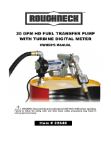
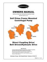
Part No.
1
2
3
4
5
6
7
8
Description
Screw M5×10
Front Cover
O-ring
Blade
Rotor
Pump Body
By Pass Spring
Seal
Q’ty
7
1
1
5
1
1
1
1
Part No.
9
10
11
12
13
14
15
Description
Motor
Spring Collar
By Pass Valve
Filter
Airproof Rubber
Filter Cover
Key
Q’ty
1
1
1
1
1
1
1
22 GPM FUEL PUMP OWNER’S MANUAL
4 of 4
DIAGRAMS AND PARTS LIST
For replacement parts and technical questions, please call 1-800-222-5381.
WARRANTY
One-year limited warranty
Distributed by
Northern Tool + Equipment Co., Inc.
Burnsville, MN 55306
NorthernTool.com
Made in China
/